Week 3 - External flow simulation over an Ahmed body.
Objective:
- To perforam grid dependancy test
- To plot Velocity and pressure contours.
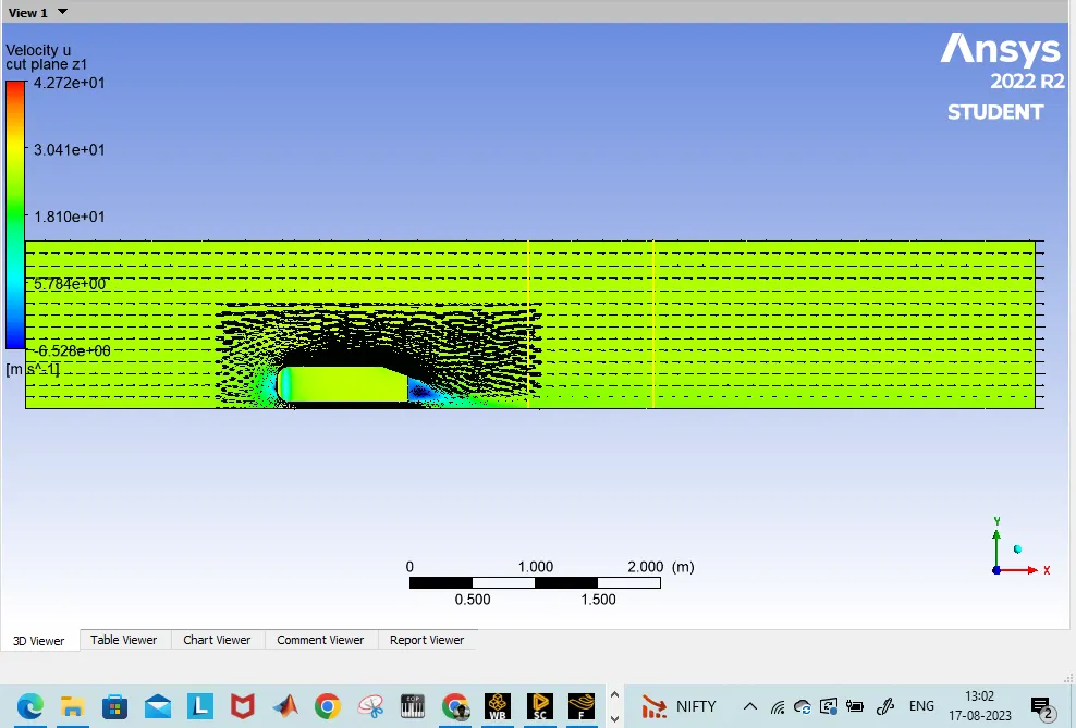
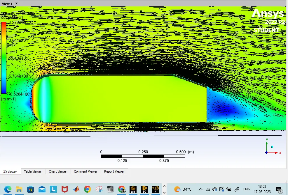
- To plot velocity vector plot clearly showing the wake region.
- To obtain coefficient Drag & Lift
Ahmed body
- Ahmed Body was one such generic bluff body proposed to study the external aerodynamics of the vehicles. The flow over the geometrically simple Ahmed reference body is used for the validation case for numerical simulations and it still continues a challenge numerical algorithms and turbulence modeling due to its complex three dimensional wake vortex interaction. The Ahmed body is a simplified car-shaped made-up of a parallelepiped with rounded edges at the front and a slanted face at the rear. The slant at the rear side of the vehicle causes the separation of flow and also a significant factor for drag forces of Ahmed body
- .The Ahmed Body was first created by S.R. Ahmed in his research “Some Salient Features of the Time-Averaged Ground Vehicle Wake” in 1984. Since then, it has become a benchmark for aerodynamic simulation tools. The simple geometrical shape has a length of 1.044 meters, height of 0.288 meters, and a width of 0.389 meters. It also has 0.5-meter cylindrical legs attached to the bottom of the body and the rear surface has a slant that falls off at 40 degrees.
- The flow for this model is turbulent, which is based on the Reynolds number determined by the body length and inlet velocity. The simulation solves for the turbulent kinetic energy in addition to the velocity field. For this simulation, we need a larger mesh size than what is usually common to resolve the turbulent flow. More specifically, we use a finer mesh downstream of the model to capture the wake zone.The simulation solves for the turbulent kinetic energy and dissipation in addition to the velocity and pressure fields.
Importance of Ahmed body
- The three-dimensional flow around a vehicle has become a subject of significant importance in the automotive industry. One apparent technique of improving the fuel efficiency of a vehicles is to reduce aerodynamic drag force by optimizing the body shape. Execution of fine aerodynamic design under stylistic constraints requires an immense understanding of the flow pattern phenomena and, especially, how the aerodynamics are impacted by changes in body shape. The flow area which is presents the major contribution to a cars drag is the wake flow backing the vehicle. The point at which the flow separates directs the size of the separation zone, and as a result the drag force
Negative pressure in Wake Region
- When the air moving over the vehicle is separated at the rear end, it leaves a large low pressure turbulent region behind the vehicle known as the wake. This wake contributes to the formation of pressure drag, which is eventually reduces the vehicle performance.
- The region of recirculating flow immediately behind a moving or stationary blunt body, caused by viscosity, which may be accompanied by flow sepration and turbulence flow, or the wave pattern on the water surface downstream of an object in a flow, or produced by a moving object (e.g. a ship), caused by density differences of the fluids above and below the free surface and gravity.
- When the vehicle is moving at a certain velocity, the viscous effects in the fluid arerestricted to a thin layer called boundary layer. Outside the boundary layer is the inviscid flow. This fluid flow imposes pressure force on the boundary layer. When the air reaches the rear part of the vehicle, the fluid gets detached. Within the boundary layer, the movement of the fluid is totally governed by the viscous effects of the fluid.The Reynolds number is dependent on the characteristic length of the vehicle, the kinematic viscosity and the speed of the vehicle. The fluid moving around the vehicle is dependent on the shape of the vehicle and the Reynolds number. There is another important phenomenon, which affects the flow of the car and the performance of the vehicle. This phenomenon is commonly known as ‘Wake’ of the vehicle. When the air moving over the vehicle is separated at the rear end, it leaves a large low-pressure turbulent region behind the vehicle known as the wake. This wake contributes to the formation of pressure drag, which is eventually reduces the vehicle performance.
Singnificance of the point of Sepration
- Separation of flow is said to occur when the direction of the flow velocity near the surface is opposed to the direction of the free stream velocity, which means (du/dy) ≤ 0. Such a situation arises when there is a negative pressure gradient near the wall. An example is subsonic diffuser or rear portion of the car.
- In the direction of flow the pressure increases which causes decreases in velocity and creates condition for separation to occur. It is important to note that, the skin-friction coefficient reaches the value zero. At this point the wall shear stress vanishes is called the separation point. Reverse flow takes place beyond point of separation. Due to reverse flow, irregular eddies are formed and lot of energy is dissipated. This region is called „Wake‟. The pressure distribution in the wake is quite different from that on the remaining boundary and this gives rise to an additional drag force on the body. Wake also leads to lateral vibration to the object which may be harmful. Also large amount of K.E. is lost.
- In the turbulent boundary layer, some of the energy is dissipated in friction, slowing airflow velocity, resulting in a pressure increase. If the increase in pressure is gradual, the process of turbulent mixing will cause a transfer of energy from the fast moving eddies to slower ones in the turbulent boundary layer. If the rate of change in pressure is too great, for example in sharp corners, the mixing process will be too slow to push the slower air molecules moving. When this happens, the boundary layer flow stops following the contours of the surface, resulting in separation. Air particles downstream of the separation region will then move towards the lower pressure region in the reverse direction to the main flow, the separation region will reattach. In the region between separation and reattachment points, air flow is circulating and this is called the „separation bubble Separation will normally occur if the resultant flow encounters a sharp edge and that is why it is always importantfor ground vehicles to have smoothly rounded edges everywhere.
Methodology
1. Modeling of Ahmed Body's geomentry
2. Meshing
3. Pre-processing
4. Setting-up physics and solving
5. Post-processing
CREATION OF AHMED BODY
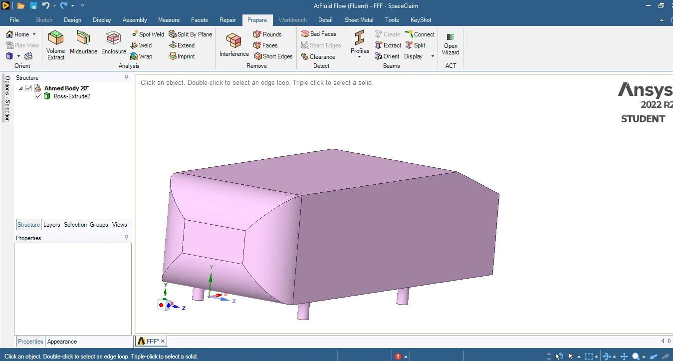
1.Import the geomentry file
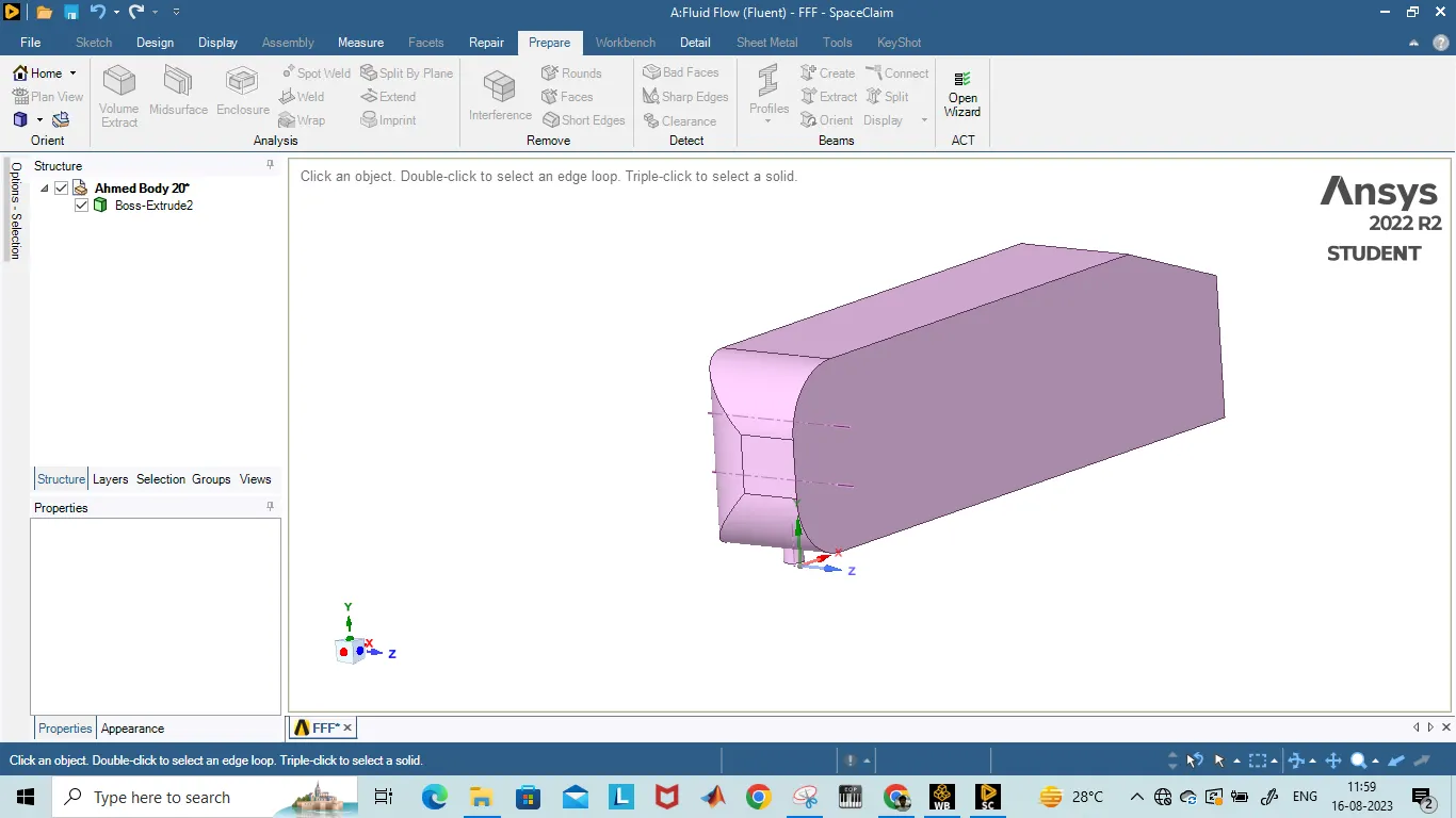
2. split geomentry along z-axis
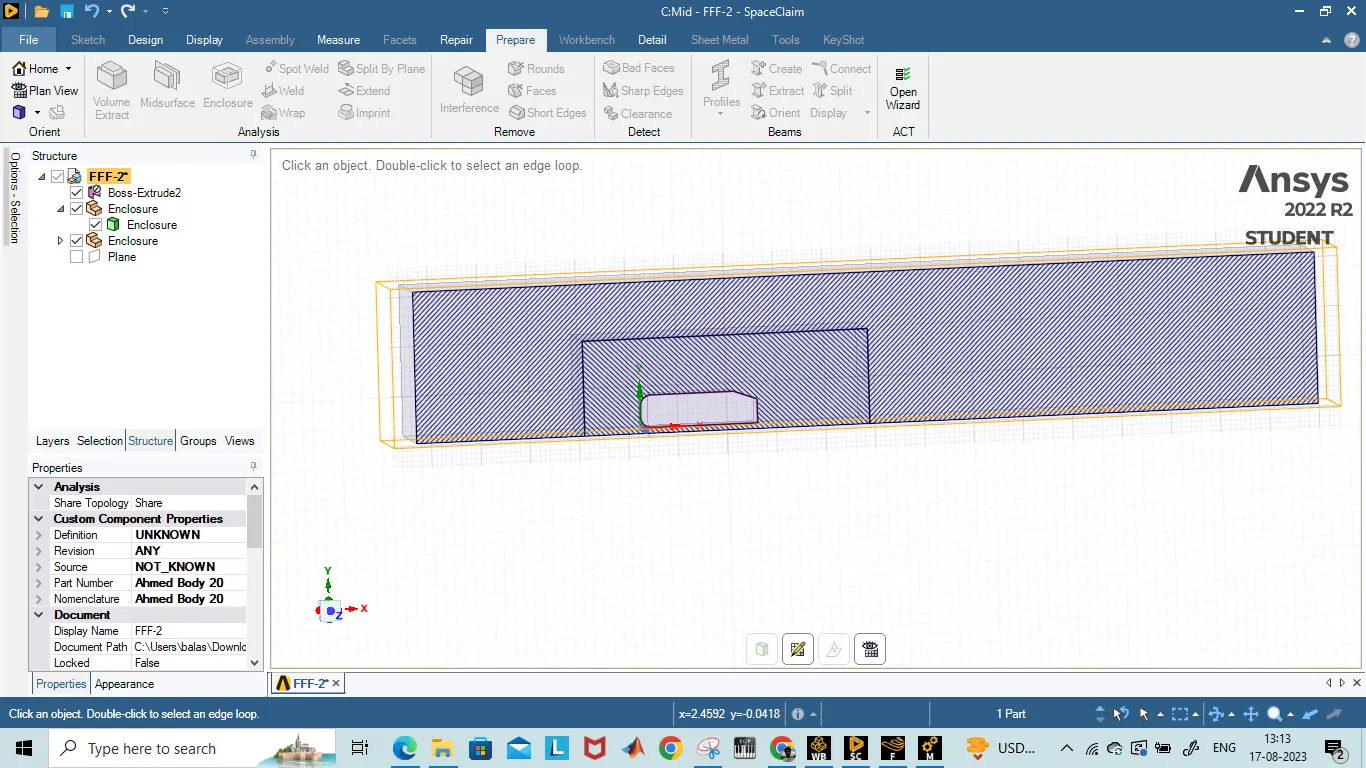
3. Creation of enclosure
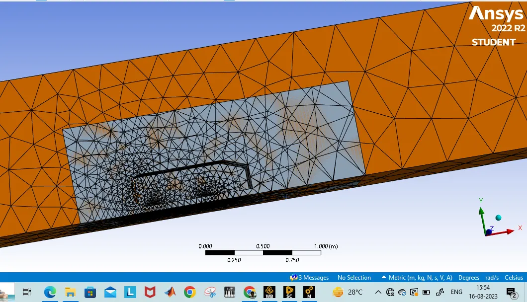
4.Baseline meshing
CASE 1:
- Outer enclosure: 100mm (elemental size)
- Inner enclosure: 50mm (elemental size)
- Face sizing for Ahmed body: 10mm (elemental size)
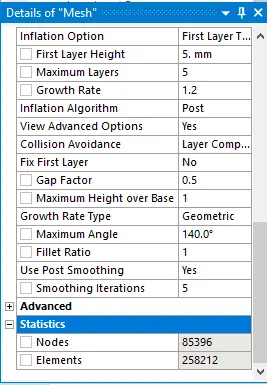
- Inflation for Ahmed body: 5 layers with growth rate of 1.2
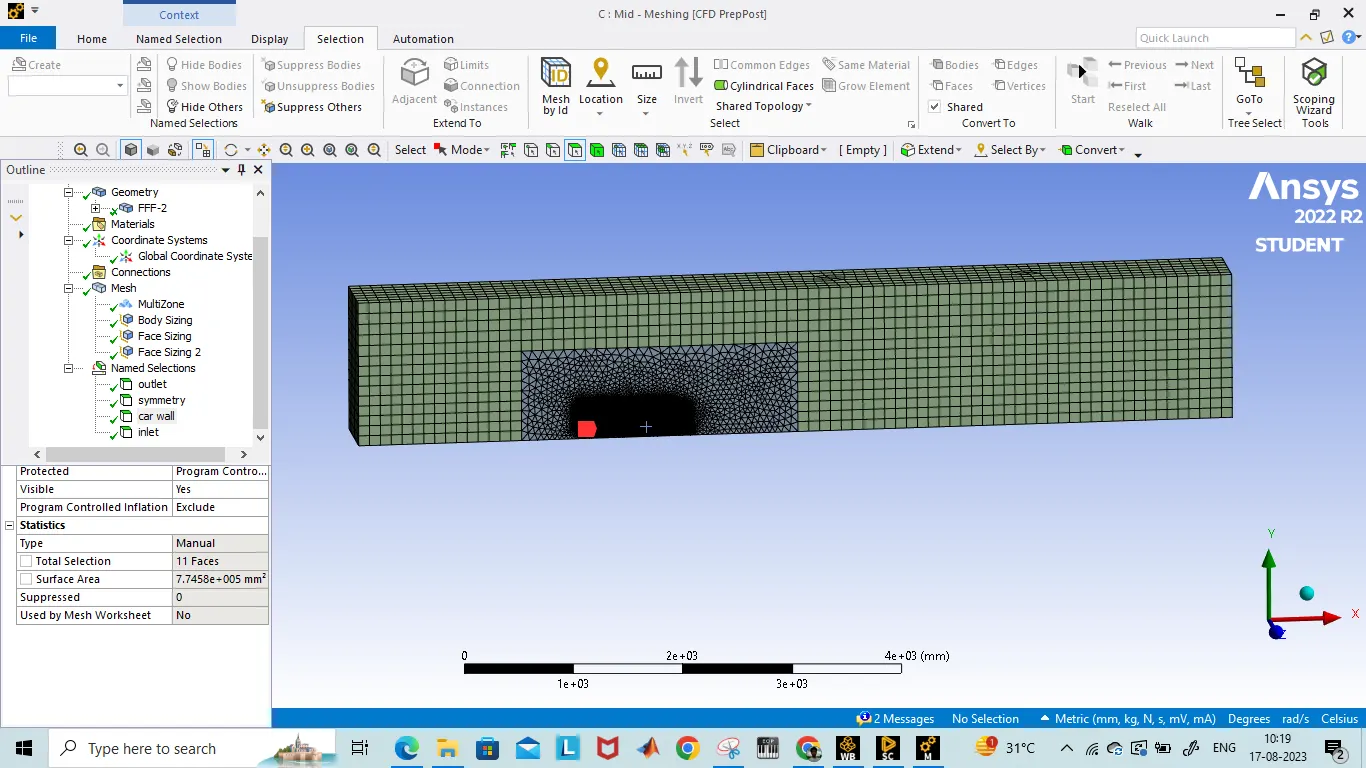
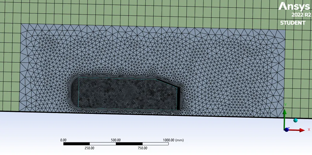
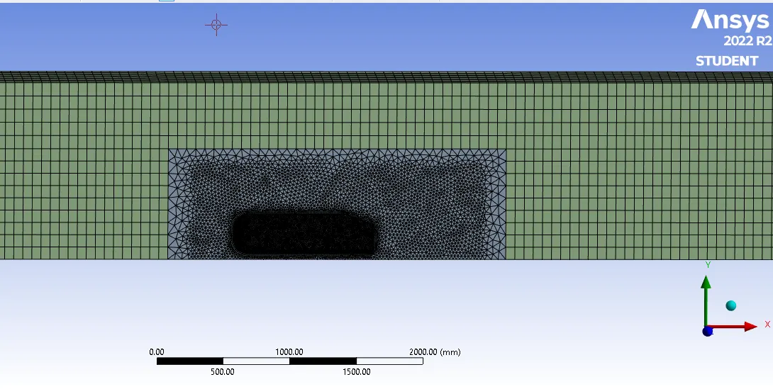
Meshing zoom in
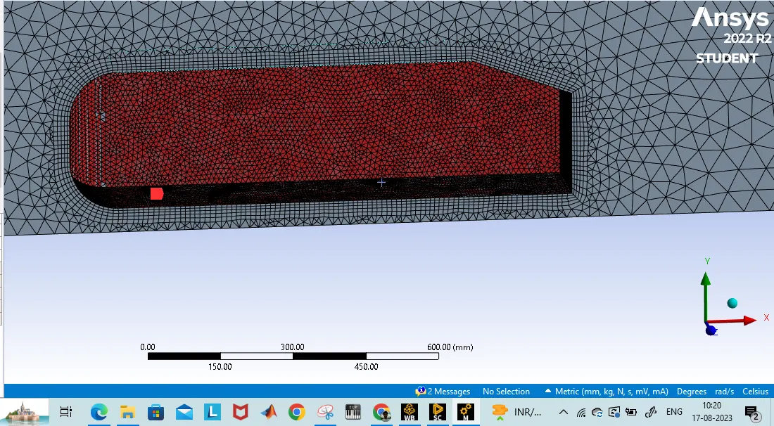
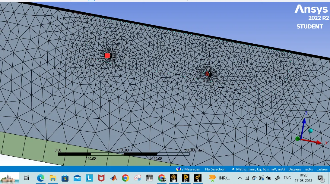
Mesh details:
SETUP PHYSICS AND SOLVING:
providing the boundary conditions
a) inlet- velocity inlet (25 m/s)
b) outlet- pressure outlet (0 pa)
c) car wall and wall- No- slip
d) Symmetry
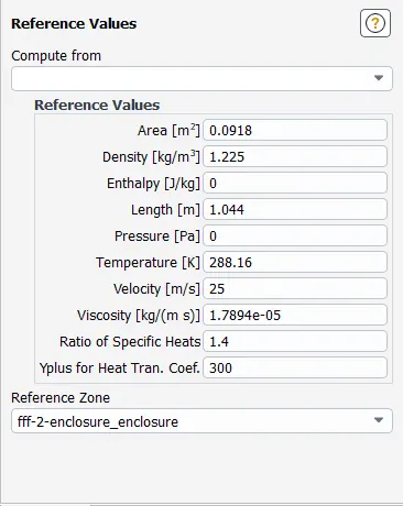
Also, set up the reference values at the inlet for the calculation of the coefficient of drag and lift.
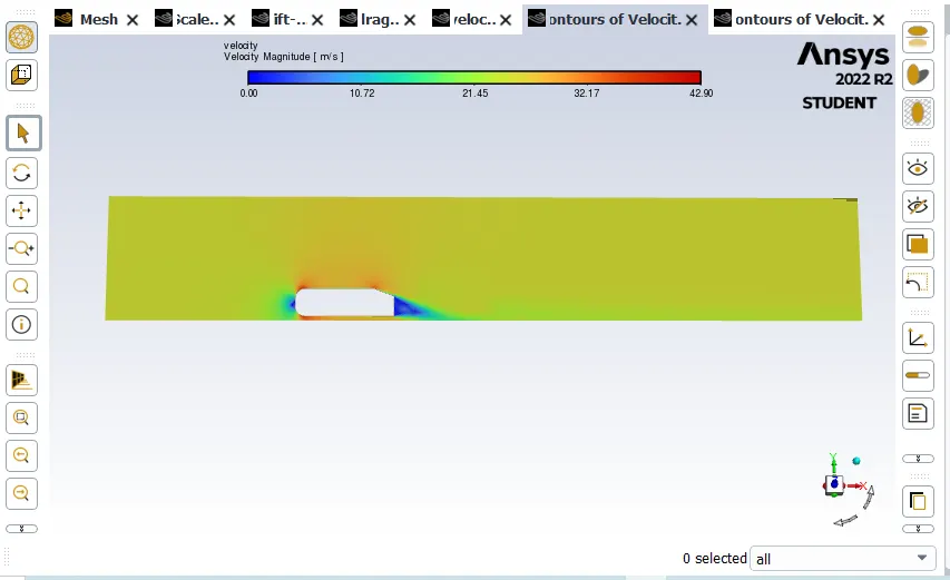
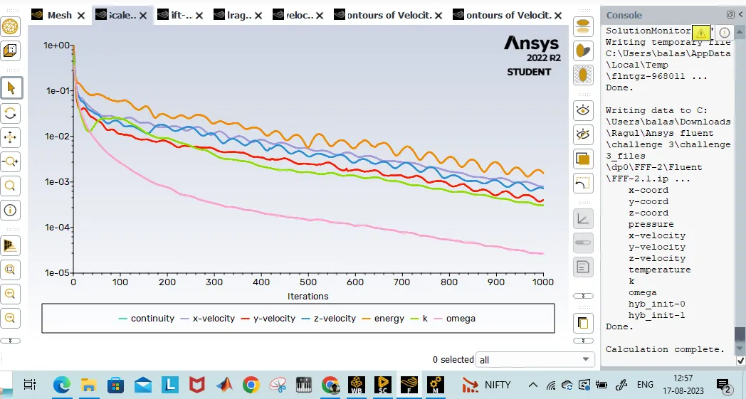
The current system is initialized using hybrid Initialization and then run for 1000 iterations and above.
velocity contour
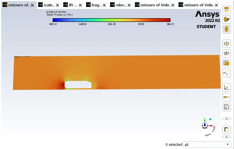
Pressure contour
Residuals
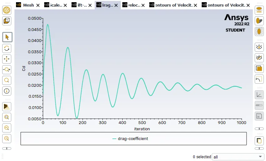
Drag coefficient 0.219
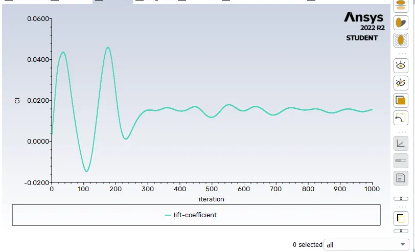
lift coefficient 0.186
Vector velocity
Vector velocity zoom in view
CASE 2:
- Outer enclosure: 80mm (elemental size)
- Inner enclosure: 35mm (elemental size)
- Face sizing for Ahmed body: 10mm (elemental size)
- Face sizing for Ahmed body leg: 5mm (elemental size)
- Inflation for Ahmed body: 5 layers with growth rate of 1.2
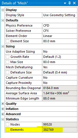
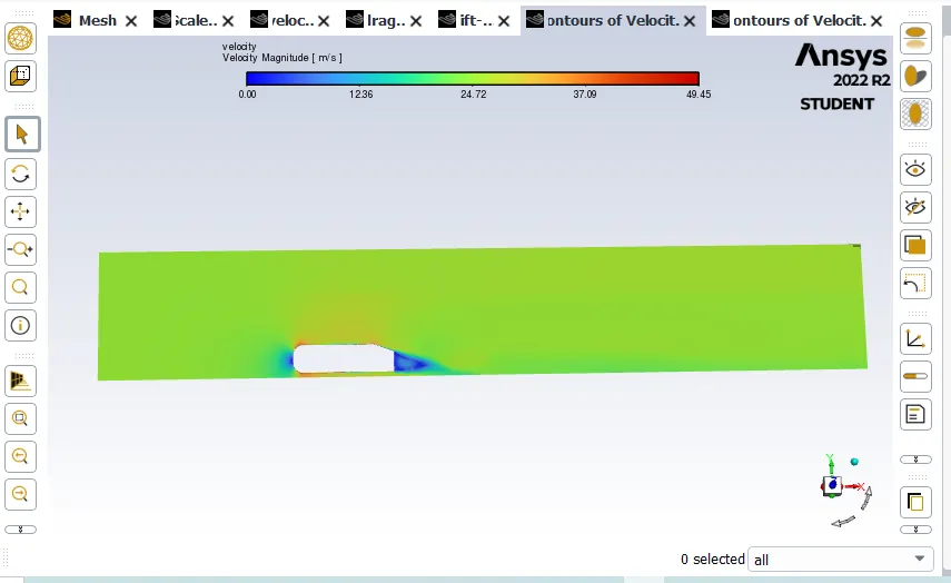
Velocity contour for mesh refinement
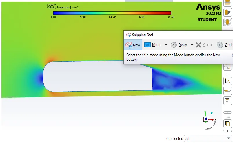
Velocity contour Zoomin view
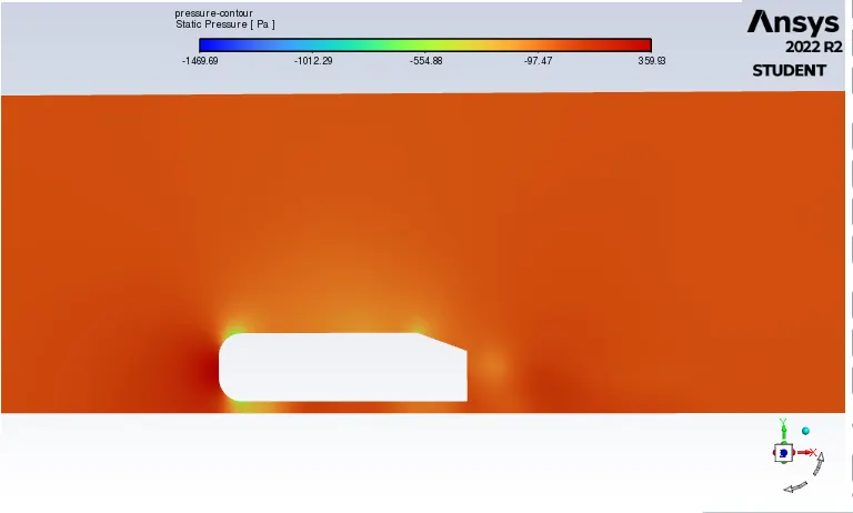
 pressure contour
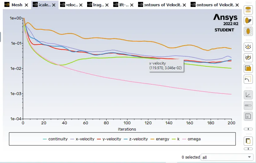
Residuals
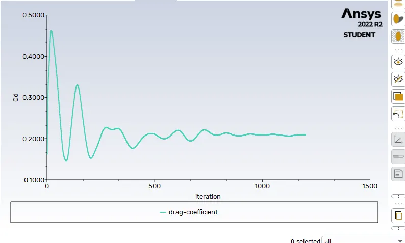
Drag Coefficient 0.208
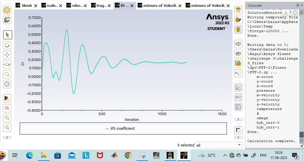
lift coefficient 0.1747
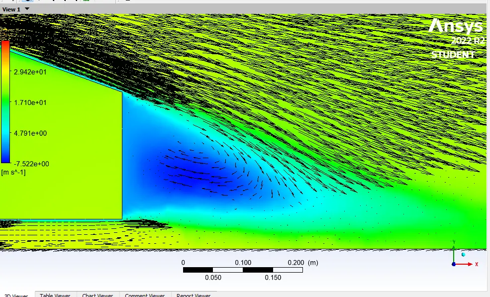
Velocity Vector
CASE 3:
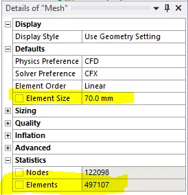
- Outer enclosure: 70mm (elemental size)
- Inner enclosure: 30mm (elemental size)
- Face sizing for Ahmed body: 10mm (elemental size)
- Face sizing for Ahmed body leg: 5mm (elemental size)
- Inflation for Ahmed body: 5 layers with growth rate of 1.2
Meshing:
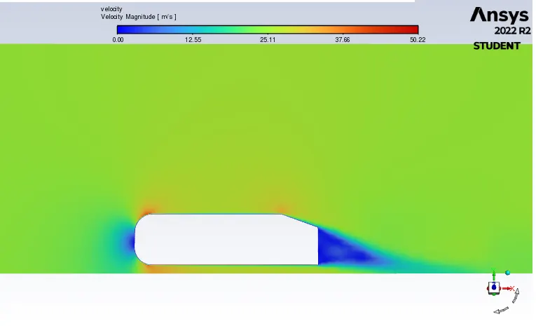
Velocity contour
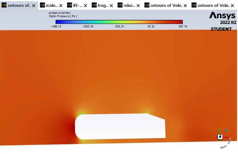
Pressure contour
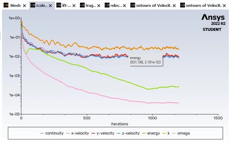
Residuals
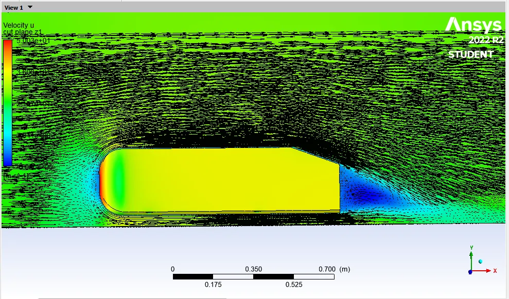
Velocity Vector
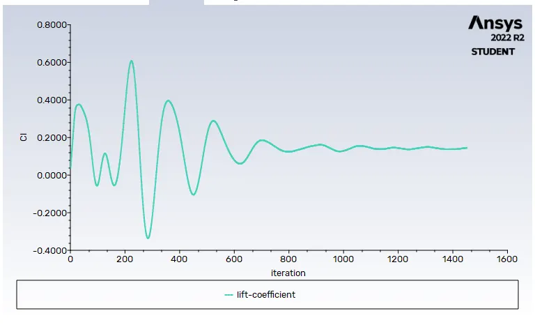
lift coefficient 0.1527
drag coefficient 0.2051
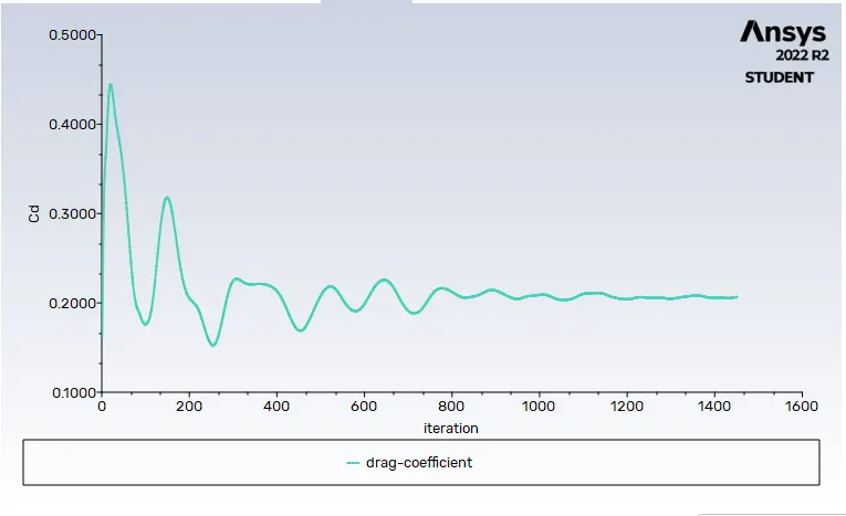
Some observations are made on the basis of the above cases
| Main case | Refine 1 | Refine 2 | |
|
Enclosure 1 element size |
100 mm | 80 mm | 70 mm |
|
Enclosure 2 element size |
50 mm | 35 mm | 30 mm |
|
Ahmed body face sizing |
10 mm | 10 mm | 10 mm |
|
Ahmed body leg face sizing |
5 mm | 5 mm | 5 mm |
|
Inflation Layers |
5 | 5 | 5 |
|
Nodes quantity |
85396 | 99528 | 122098 |
|
Elements |
258212 | 382769 | 497107 |
|
Coefficient of drag |
0.219 | 0.208 | 0.2051 |
|
Coefficient of lift |
0.186 | 0.1747 | 0.1527 |
Conclusion
- The baseline mesh gave a poor result, it wasn't able to capture the flow around the Ahmed body and the wake structure, due to coarse mesh.
- The refined mesh gave better results. The plots show the wake formation accurately and the flow around the Ahmed body was also captured pretty well.
- There is a variation of pressure across the Ahmed body. The pressure in front of the body is positive because that's the location where the flow first comes in contact with the body and comes to rest. At the corner, the flow accelerates, thereby decreasing the pressure.The reason behind negative pressure in the wake region is due to flow separation, recirculating flow.