Week 3 - External flow simulation over an Ahmed body.
1. Ahmed body and its importance
The Ahmed body is a simplified car body used in the automotive field to study the impact of the flow pattern on drag. The external aerodynamics of the car defines many significant traits of an automobile like stability, comfort, and fuel consumption at high speeds. The flow around the vehicle is characterized by high turbulent and three-dimensional flow separations as well as there is a growing need for more insight into the physical features of these dynamical flows. The Ahmed Body is a simplified car, used in the automotive field to investigate the flow analysis and find the wake flow around the body. Ahmed body is made up of a round front part, a moveable z-slant plane in the rear of the body to study the detachment phenomena at different angles, and a rectangular box that links the front part and the rear slant plane. The principal objective to study such a simplified car body is to tackle the flow processes involved in drag production. Through perceiving the mechanisms involved in creating drag one can be able to design a car to minimize drag and therefore reducing fuel consumption and maximize vehicle performance.
2. The reason for the negative pressure in the wake region
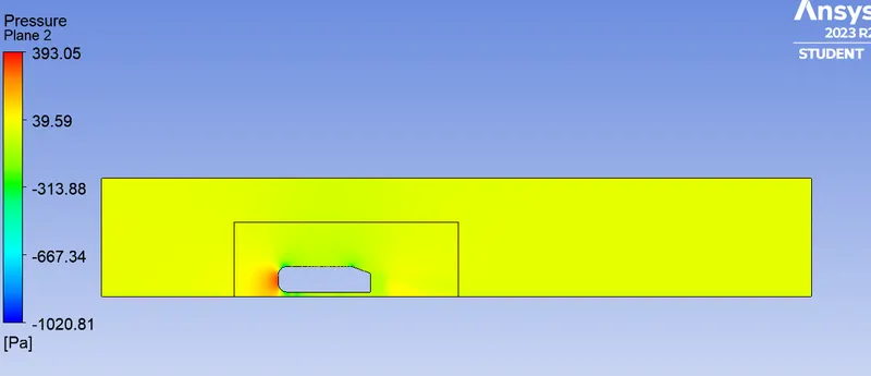
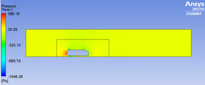
The flow behind an object separates from the surface and creates a highly turbulent region behind the object, called the wake. The pressure inside the wake region remains low as the flow separates and a net pressure force (pressure drag) is produced. In other words, due to the production of pressure drag being produced from flow separation, the pressure in the wake region is low. This is what is causing the vacuum.
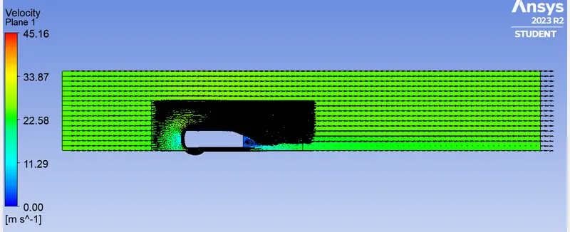
The fluid just after leaving contact with the slope still possesses momentum in it and the fluid particles near the surface almost show the no-slip region which means the very least possible velocity of the fluid particles is in contact with the slope and base of the rear part. Thus the fluid particles away from the rear region having the higher pressure beside the wake region try to approach from the higher pressure region to the lower pressure region thus creating a circularity exactly in the wake region created.
The body penetrating the fluid creates a region of emptiness just beside its end due to the nature of the geometry of the body here which can be seen least in the case of a perfectly streamlined shaped body. This emptiness created is a low-pressure region towards which the fluid column is exactly behind the wake region which of atmospheric pressure tries to fill the space thus dragging the fluid column with it thus creating the region of vorticity. This also results in a huge pressure gradient in the region exactly rear of the body creating the negative pressure at the end. Also, this is the layman’s reason why there is negative gauge pressure in the wake region.
3. The significance of the point of separation
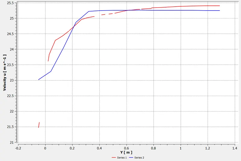
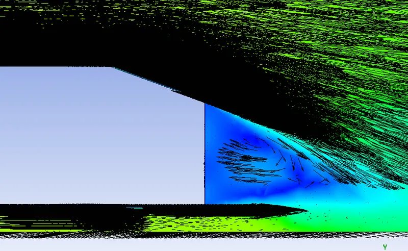
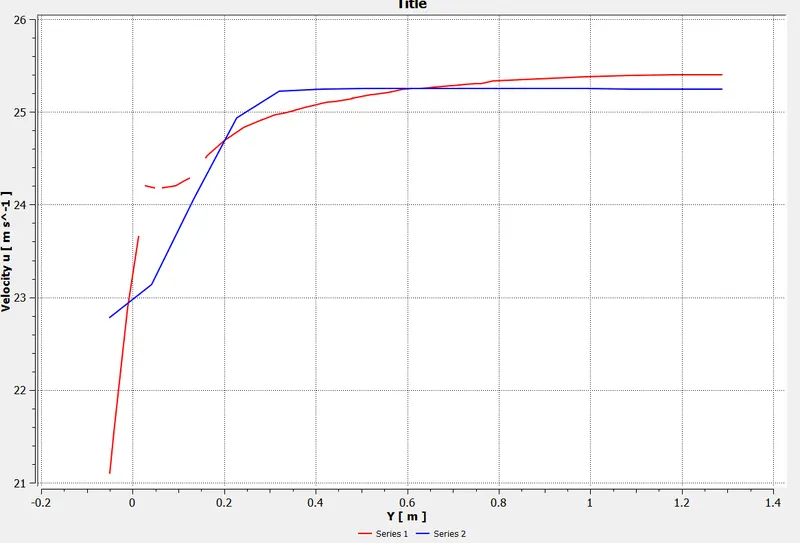
The fluid separation point can be defined as a point where the dv/dy i.e. gradient of velocity goes zero along with the dp/dx = 0, for the specific point. In more simplified terms, we can say that at the point where the velocity gradient goes zero and the pressure gradient along the x-direction goes zero, the point of separation starts occurring or the negative pressure gradient starts forming after that point. The point of separation cannot be understood just by a single contour in a hard and fast way. It can be supportively studied with the help of the dp/dx plots or velocity plots w.r.t the Y direction and other such plots in which we can see the nature of such physical properties like dp/dx=0, and dv/dy=0 experiencing in a particular region of fluid and body interaction.
Simulation setup
Geometry:
Load Ahmed body into the discovery.
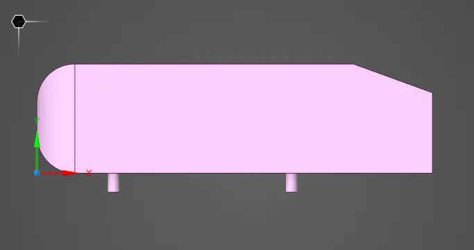
Go to prepare and click on the enclosure and select the Ahmed body. Enter the enclosure dimensions as shown below.
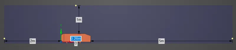
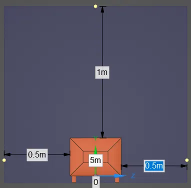
Next, once the enclosure is done, create another enclosure close to Ahmed body so that we can refine the mesh in that enclosure.
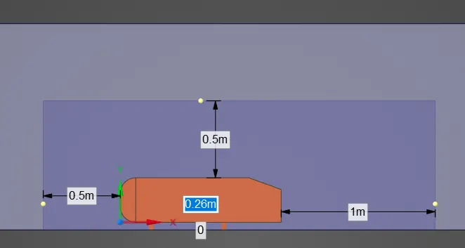
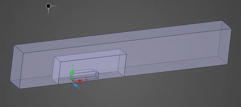
After both enclosures, it will look like this. Check for interference and fix it.

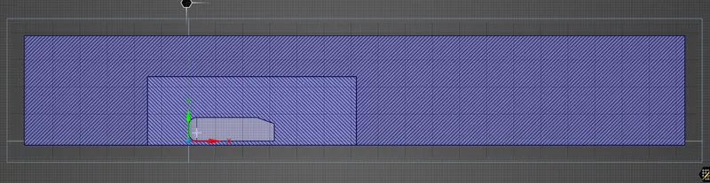
Using the split body option, split the body into two halves by using an XY plane as a cutter. Remove the unwanted regions.
Mesh:
Case 1:
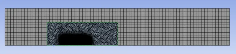
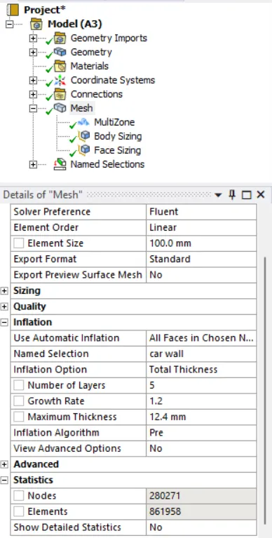
Outer enclosure: 100mm (elemental size)
inner enclosure: 50mm (elemental size)
Face sizing for Ahmed body: 5mm (elemental size)
Inflation for Ahmed body: 5 layers with a total thickness of 12.4mm
Fluent:
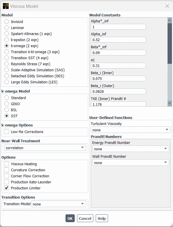
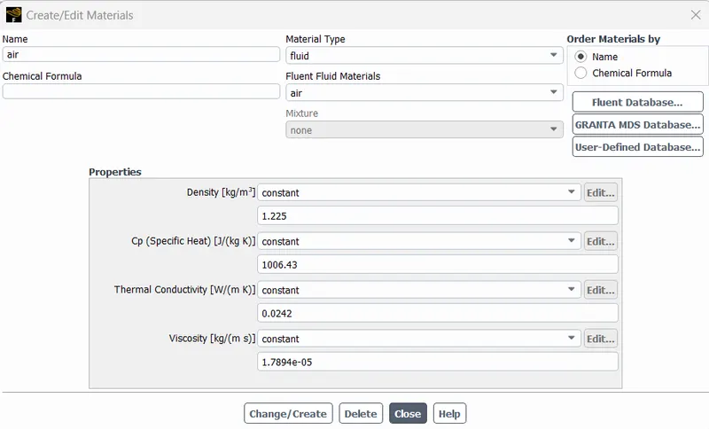
Results:
Plots:
Residual:
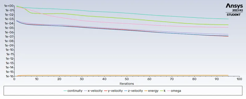
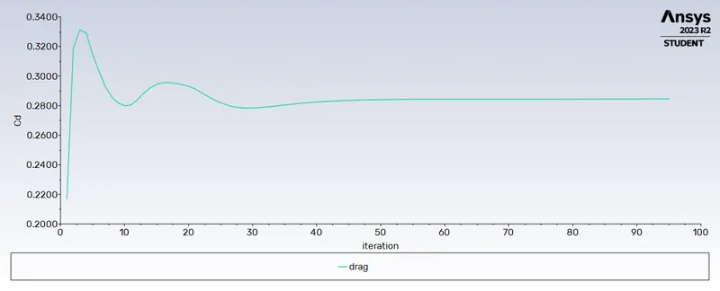
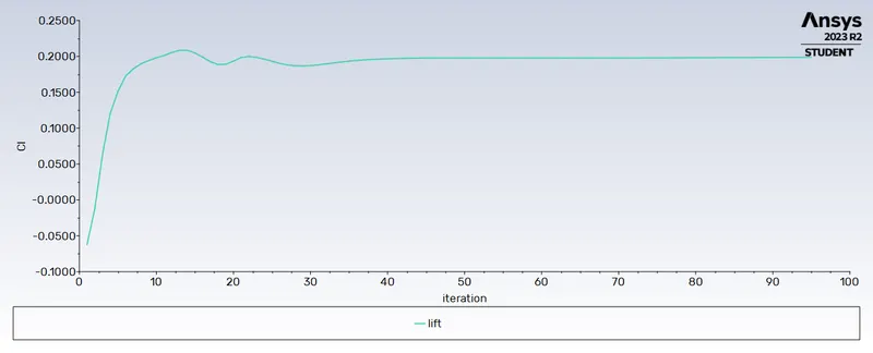
Drag and lift coeff:
Contours:
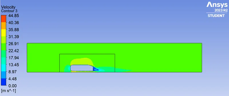
Velocity:
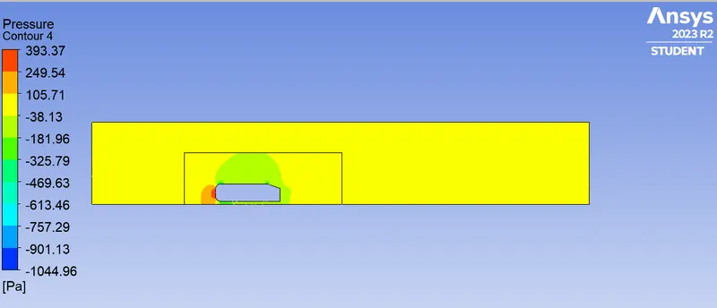
Pressure:
Vector plot:
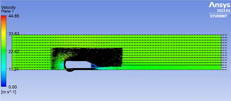
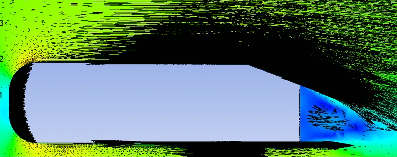
Velocity variation:
Case 2:
Outer enclosure: 100mm (elemental size)
inner enclosure: 40mm (elemental size)
Face sizing for Ahmed body: 5mm (elemental size)
Inflation for Ahmed body: 5 layers with a total thickness of 12.4mm
Results:
Plots:
Residual:
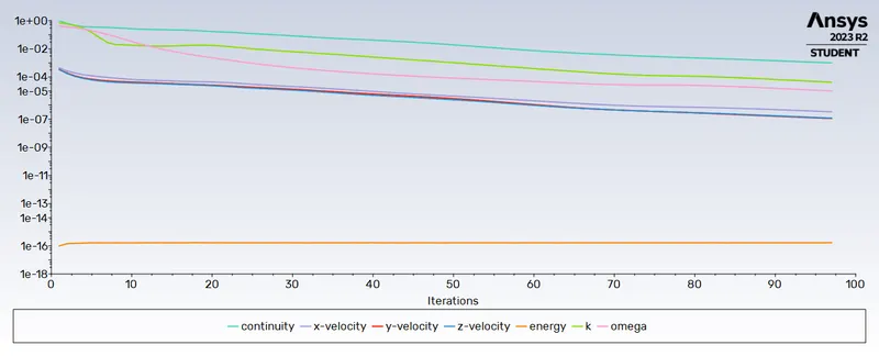
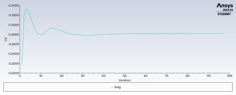
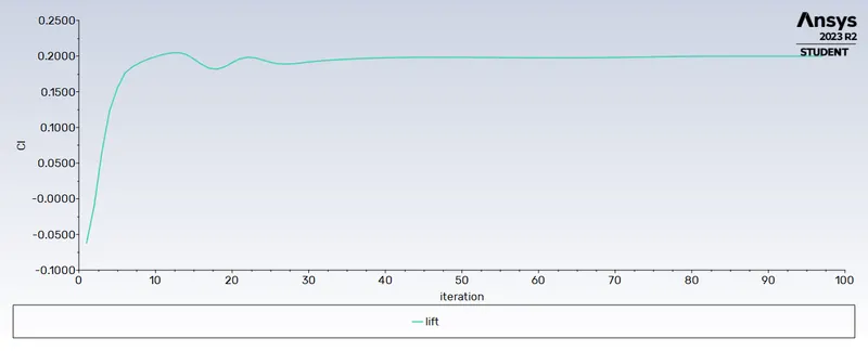
Drag and lift coeff:
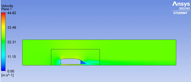
Contours:
Velocity:
Pressure:
Vector plot:
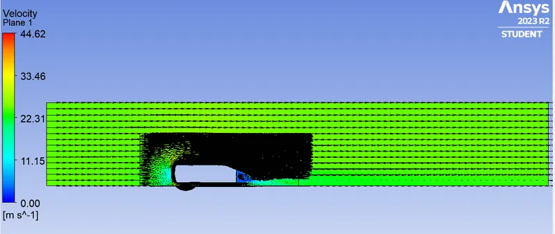
Velocity variation:
Case 3:
Outer enclosure: 90mm (elemental size)
inner enclosure: 40mm (elemental size)
Face sizing for Ahmed body: 5mm (elemental size)
Inflation for Ahmed body: 5 layers with a total thickness of 12.4mm
Results:
Plots:
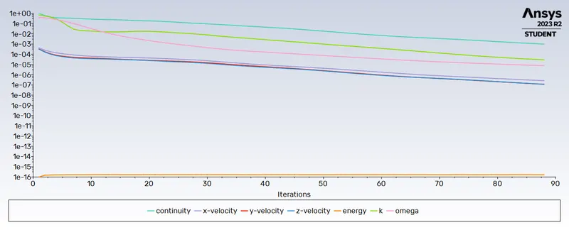
Residual:
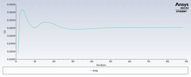
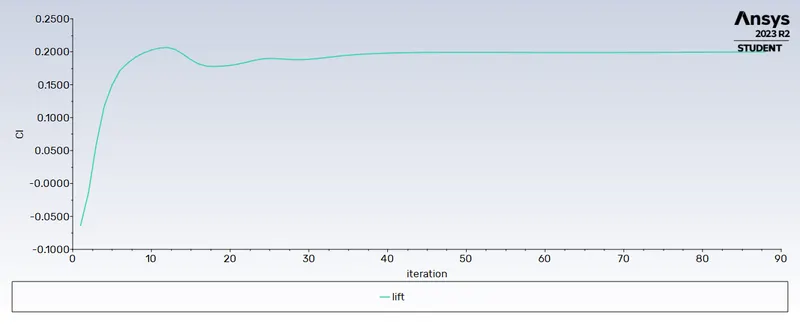
Drag and lift coeff:
Contours:
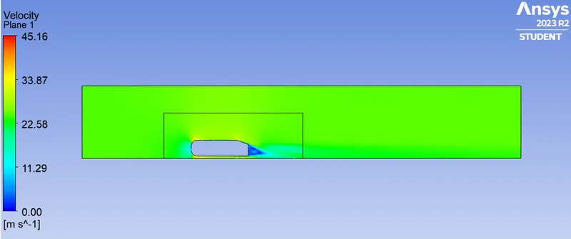
Velocity:
Pressure:
Vector plot:
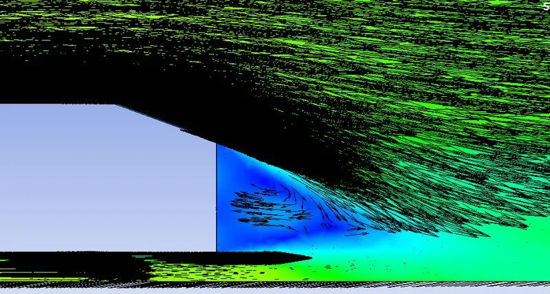
Velocity variation:
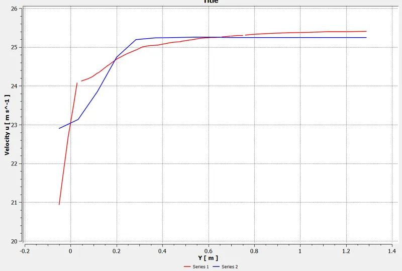
| Grid Independence test | |||
| Number of cells | Cd | CL | |
| case 1 | 861958 | 0.2846 | 0.1999 |
| case 2 | 908469 | 0.2822 | 0.1998 |
| case 3 | 911316 | 0.2811 | 0.1997 |