Week 3 - External flow simulation over an Ahmed body.
AIM:-
The project is to simulate the Ahmed body for the grid dependency and to see the effect of mesh sizing on the result of velocity and pressure distribution around the Ahmed body.
Ahmed body:-
It is a generic car body or simplified automobile body, which is being used in automotive industries to simulate the flow charactristics around the Automobile. The fluid flow around the Ahmed body very accurately resembles the critical flow charcteristics around the Automobile.
SOLUTION:
1: GEOMETRY:-
Step 1:-
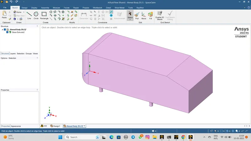
Import Ahmed body geometry into spaceclaim.
Step 2:-
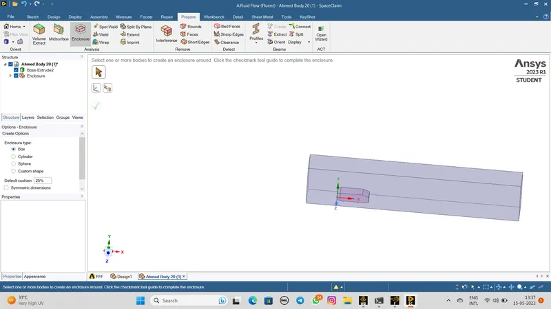
Using Enclosure option in spaceclaim with a dimension and generate a domain (Unit is in= Meter)
Length from X axis is 5 Meter
Length back side is 2 Meter
Base is 0
Height is 1 Meter
The result shown as a below figure,
Step 3:-
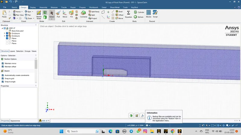
The geometry of Ahmed body ready to meshing and also clear the interfence error.
Step 4:-
After that select the part and give the name as,
Inlet
Outlet
Symmetry
Walls
Step 5:-
After this process the Fluent step is start,
The reference values are viscous model is velocity is 25m/s. Energy equation is model K-Epsilon.
Material- Air
Boundary conditions-
Inlet - Type= Velocity inlet
Velocity Magnitude=50m/s
Temperature=300k
Otulet
type- Pressure outlet
Gauge pressure = 0pa
Symmetry -
Type- Syemmetry
Walls
Type wall
CASE:-1
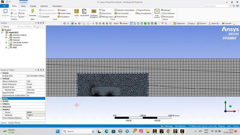
In this case we are proceding with autogenereted mesh by Ansys fluent
Nodes:46089
Elements:176674
After that make a setup and generate the results.
The Resuduals as below,
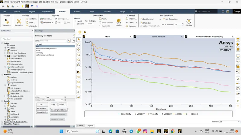
Results:-
Pressure plot as below,
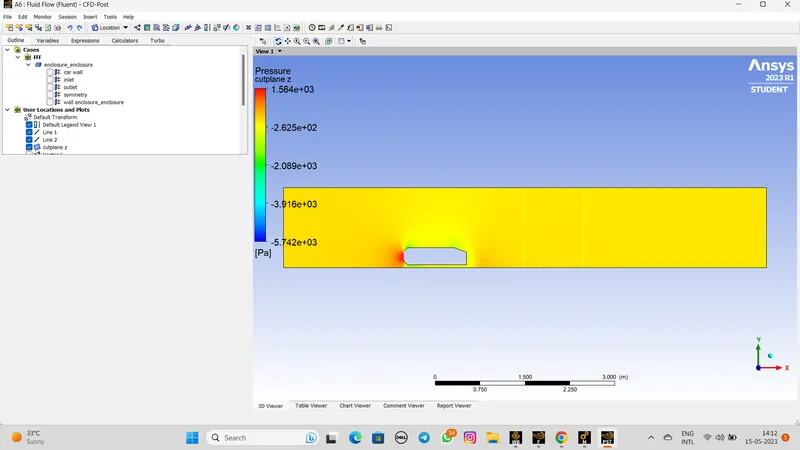
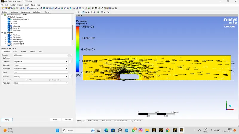
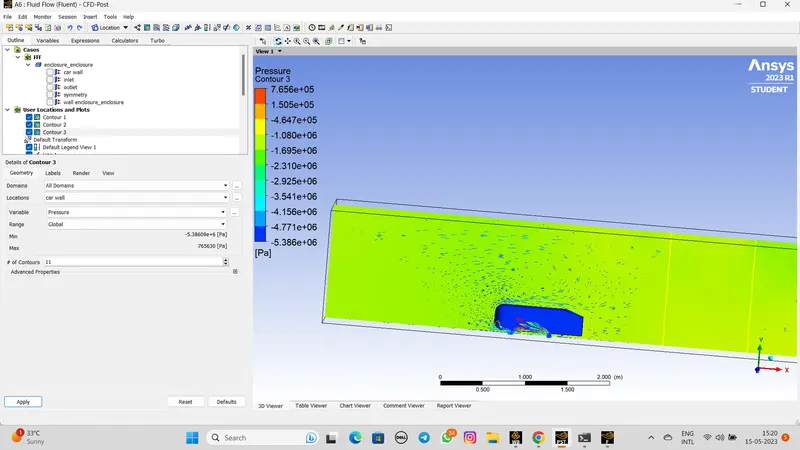
Vector plot- Pressure:-
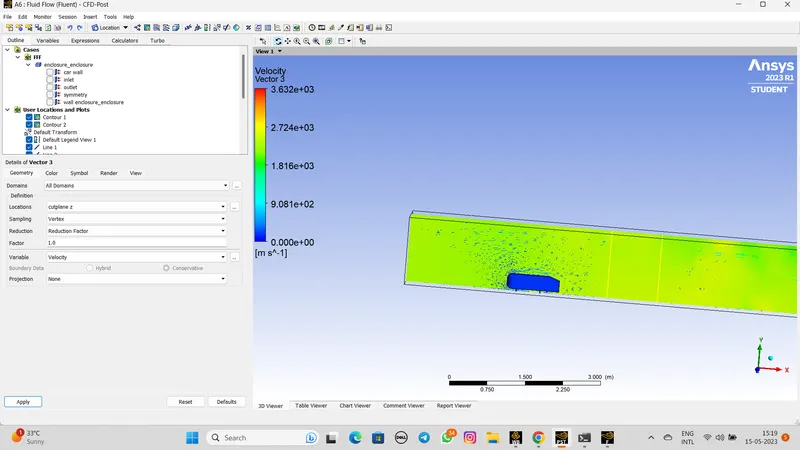
The Velocity plot:-
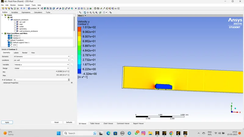
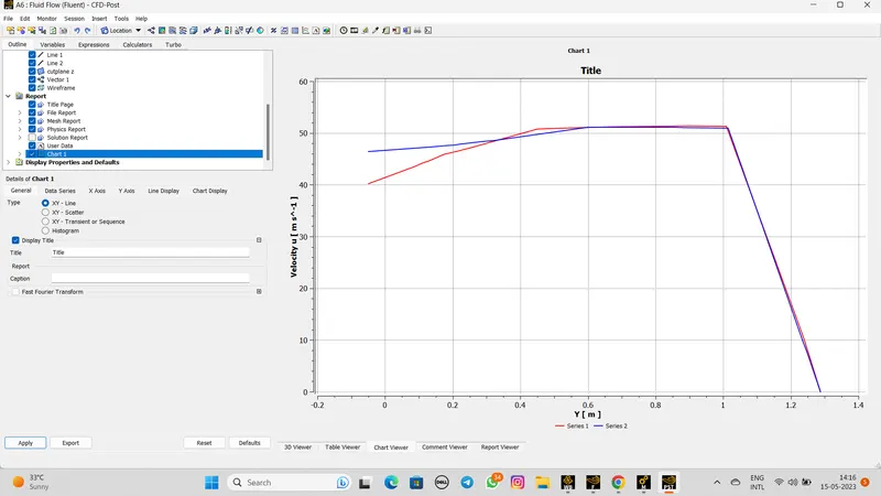
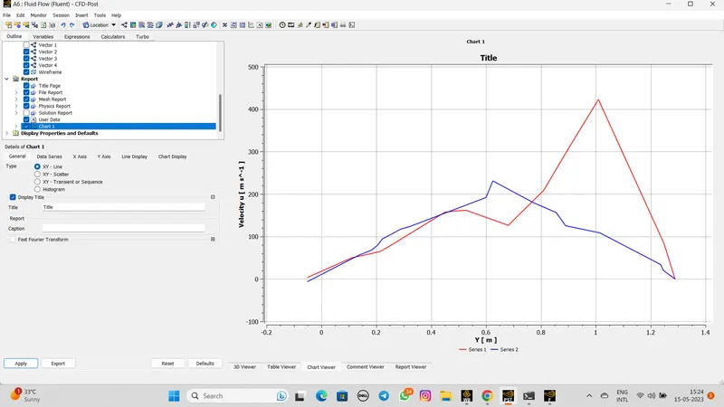
The Chart figure as below,
 +
+
CASE 2:-
- Open geometry
- Import the Ahmed body from files
- Split the body into half
- provide Enclosure to body according given dimensions.
- Input plane and select XY plane and cleare the interference errors.
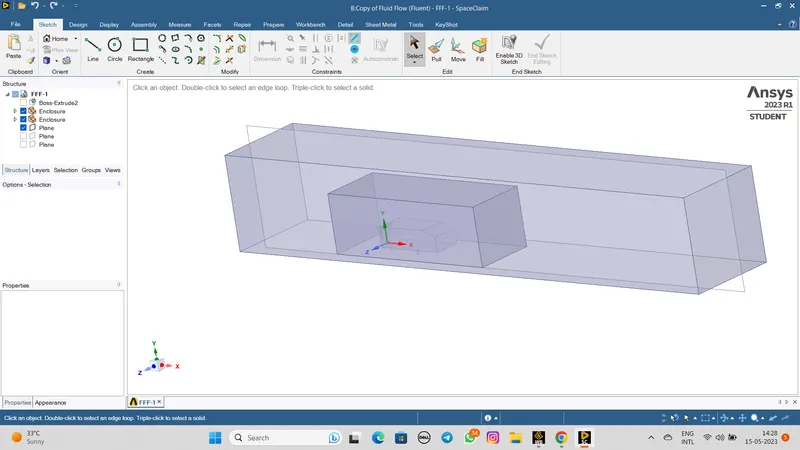
- The geometry step is done look like as below,
- After that start the mesh section, start with name the boundary wich are inlet,outlet,symmetry wall, car-wall.
- Then provide specific element size and generate the mesh.
- Then we have to provide the mesh method for the outer enclosure and set the multizone method.
- After that add to body sizing for the inner enclosure to make it more refined in inner bounding box.
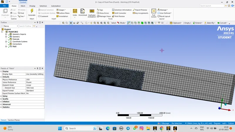
- The mesh is complete and figure as below,
Setup:-
- First check the mesh from domain section.
- After that check boundaries and material property.
- set the turbulence model K-OMEGA
- Now, set the boundary conditons.
Inlet velocity= 5 m/sec
Outlet - guage pressure = 0pa
car wall- No sleep
- Now initialize the problem with hybrid initialization.
- Then go back to result section and add velocity and pressure contours along plane.
RESULTS:-
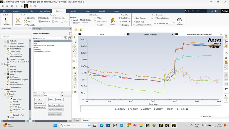
The Residual plot as below,
 +
+
The Vector - velocity
The Vector - pressure
The chart:-
CONCLUSION:-
- Select the wall volume to make it visible and also color it with the variable needed to be observed.
- We use CFD to illustrate flow separation for the case of flow over a Ahmed body along the wall. the flow is steady and 2D and vector plot show outlet flow velocity vector generated by a solution.