Week 3 - External flow simulation over an Ahmed body.
Aim: External flow simulation over an Ahmed body using Ansys Fluent.
Objective:
- To describe Ahmed's body and its importance.
-
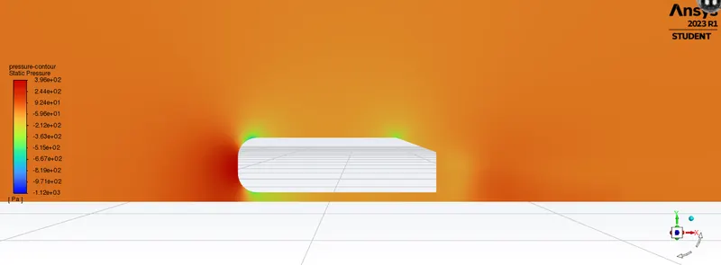
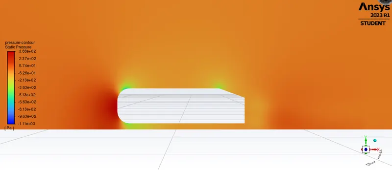
To explain the reason for the negative pressure in the wake region.
-
To explain the significance of the point of separation.
-
To find Velocity and pressure contours.
-
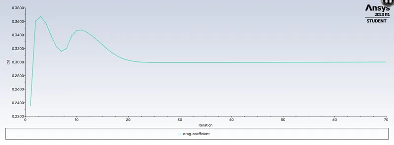
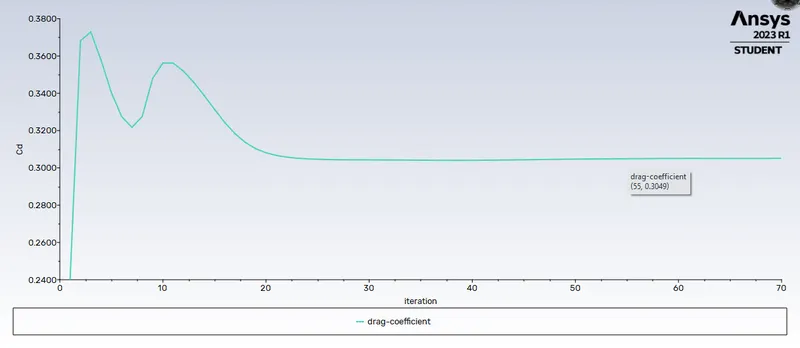
The drag coefficient plot for a refined case. ( For velocity of 25m/sec, the drag coefficient should be around 0.33).
-
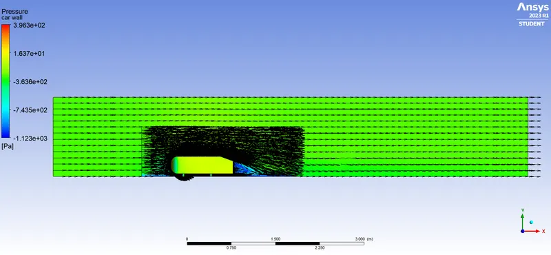
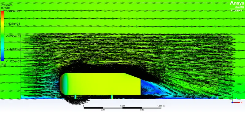
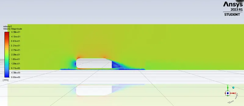
The vector plot clearly shows the wake region.
-
To perform the grid independency test and provide the values of drag and lift with each case.
Theory:
- Description of Ahmed's body
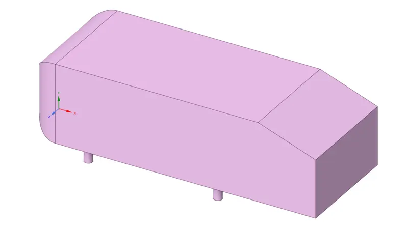
The Ahmed body is a generic car body (a simplified vehicle model). The airflow around the Ahmed body captures the essential flow features around an automobile and was first defined and characterized in the experimental work of Ahmed. Flow around the Ahmed body is a well-known CFD benchmark for external aerodynamics. The Ahmed body is a generic car model first proposed by [Ahmed et al., (1984)]. All ground vehicles can be termed as bluff bodies moving close to the road surface.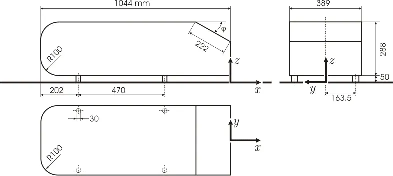
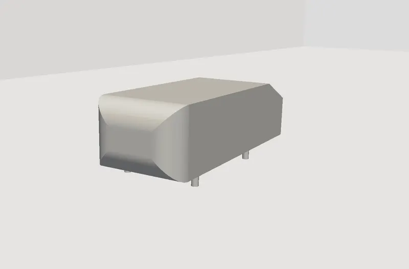
- Ahmed Body and Its Importance:- Ahmed body is a simplified car body and was first created by S.R Ahmed. This shape provides a model to study geometrical effects on the wakes of ground vehicles. This is the kind of baseline geometry for automobile bodies.
- When the air moving over the vehicle is separated at the rear end, it leaves a large low pressure turbulent region behind the vehicle known as the wake. This wake contributes to the formation of pressure drag, which is eventually reduces the vehicle performance
- The separation point is the point where the air stops "sticking" to an object that is moving through the air. When an object is moving through the air, the air molecules push back on it and resist the object's movement - this resistance is called pressure drag.Boundary layer separation occurs when the portion of the boundary layer closest to the wall or leading edge reverses in flow direction. The separation point is defined as the point between the forward and backward flow, where the shear stress is zero.
Simulation Setup:
- Geometry
- Inner Enclosure
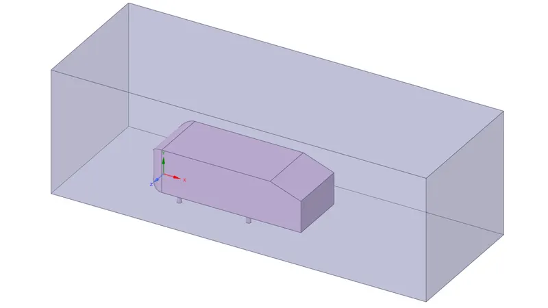
- The right face is located at a distance of 1 m from the right side face of Ahmed's body along the X axis.
- The left face is located at a distance of 0.5 m from the left side face of Ahmed's body along the X axis.
- A top face of the enclosure is at a distance of 0.5m from the top side face of the Ahmed body along the Y axis.
- The bottom face of the enclosure is attached to the bottom face of the Ahmed body along the YZ plane.
- The front and back face of the enclosure is at a distance of 0.26 m along the Z axis.
- Geometry Baseline
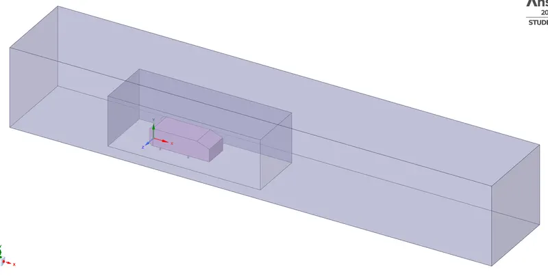
- The right face is located at a distance of 5m from the right side face of Ahmed's body along the X axis.
- The left face is located at a distance of 2m from the left side face of Ahmed's body along the X axis.
- A Top face of the enclosure is at a distance of 1 m from the top side face of the Ahmed body along the Y axis.
- The bottom face of the enclosure is attached to the bottom face of the Ahmed body along the YZ plane.
- The front and back face of the enclosure is at a distance of 0.5 m along the Z axis.
Case 1
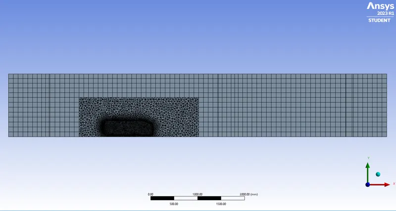
- Meshing
- Total mesh elements are 433498.
- Total nodes are 129451.
- Hexahedral mesh is used for the first box and element size is 105mm.
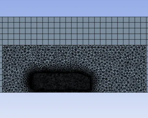
- For body sizing the element size is 55mm.
- For face sizing(car body) is 13mm.
- There are 5 inflation layers around the Ahmed body with a max thickness of 12.5mm.
- Solver Setup
- General Setup
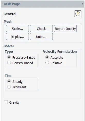
- Viscous model is the k-epsilon standard model.
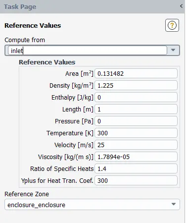
- Boundary Condition
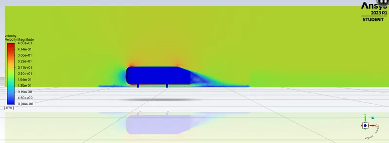
- Velocity Magnitude
- Pressure
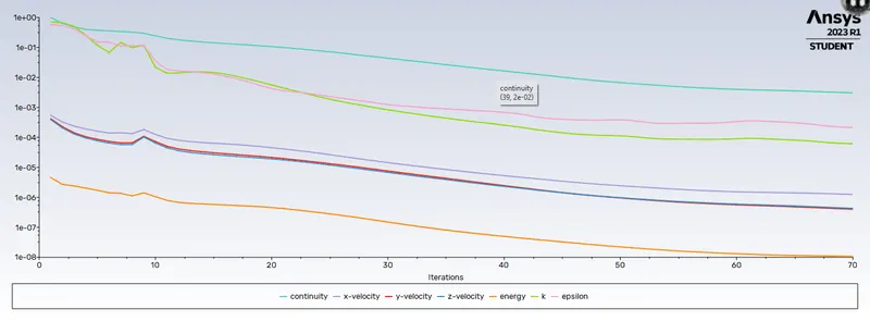
- Scale Residuals
- Drag-coefficient
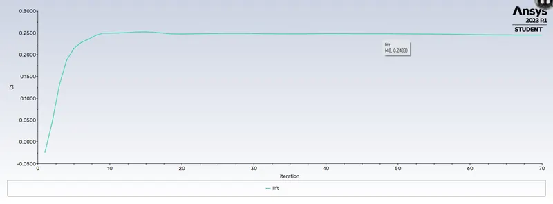
- Lift Plot
-
Drag-coefficient of the car-wall is 0.30002087.
-
Lift of car-wall is 0.24509681.
- Velocity Vector Plot
- General Setup
Case 2
- Total mesh elements are 344746.
- Total nodes are 104594.
- Hexahedral mesh is used for the first box and element size is 110mm.
- For body sizing the element size is 60mm.
- For face sizing(car body) is 15mm.
- Velocity magnitude
- Pressure
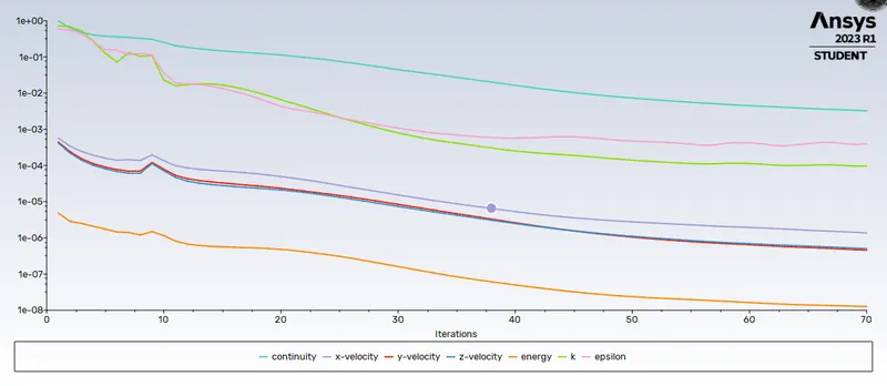
- Scale Residuals
- Drag Coefficient
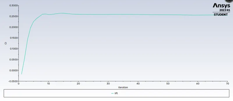
- Lift Coefficient
-
Drag-coefficient of the car-wall is 0.30512234.
-
Lift of car-wall is 0.25423924.
- Velocity Vector Plot
- Velocity magnitude
Result
- Grid Count
The important takeaway is that drag coefficient does not vary significantly when the mesh is made finer. While the drag coefficient does vary when the mesh is made more coarse. This means that the grid dependence test has passed.
Drag-coefficient Lift-coefficient Elements Nodes Case 1 0.30002087 0.24509681 433498 129451 Case 2 0.30512234 0.25423924 344746 104595
Conclusion
- The simulation of the Ahmed Body runs well and is in some agreement with experimental and empirical data on the body.
- There are regions behind the body where wakes are formed, circling regions of low velocity which induce a considerable amount of velocity drag on the body
- rid Dependence Test was conducted and the test was successful, an additional observation was also made - the drag coefficient decreases as the number of elements increases. This decrease is very small and may be considered insignificant.
- The baseline mesh gave a poor result, it wasn't able to capture the flow around the Ahmed body and the wake structure, due to coarse mesh.
- As the wake flow is the main contributor to the drag force(pressure drag), the point of separation is an important aspect of the flow. The more attached the flow is to the body the recirculation zone will be smaller and hence reduce the adverse effect of pressure drag, improving the fuel efficiency of the body.
References
https://www.cfd-online.com/Wiki/Ahmed_body
https://www.simscale.com/docs/validation-cases/aerodynamics-flow-around-the-ahmed-body/