Week 3 - External flow simulation over an Ahmed body.
ANSWER-
Aim-Simulation of flow over ahmed body.
Ahmed body and its importance.
Explain wake region and point of seperation their significance.
Pressure distribution and reason of negative pressure gradient in wake region.
Theory-
Ahmed body-It is a basic car body with simple outer feature rather generic vehicle body.
Its simple outer feature allow to capture basic and relevent properties of automobile vehicle when fluid flow over it is simulated.
after results getting validated with experimetal values,this data can be used to design new vehicle model.
The Ahmed Body was first created by S.R. Ahmed in his research “Some Salient Features of the Time-Averaged Ground Vehicle Wake” in 1984. Since then, it has become a benchmark for aerodynamic simulation tools.
The drag force is an important factor considering fuel consumption. As the drag force increases the fuel consumption also increases.
the Ahmed body is a benchmark model widely used in the automotive industry for validating simulation tools,because several experimental research has been done and data is available to validate the results.
boundary layer-When fluid flow over a solid surface ,layers of fluid particle attached to solid surface is considered to have velocity of surface which is zero to avoid slip, this offer a resistance to the layer of fluid just above of it hence this layer velocity drops from free stram velocity.
A thin layer of fluid in the vicinity of solid body when fluid velocity vary from zero to free stream velocity in the direction normal to solid body surface is call boundary layer.
In boundary layer viscous force dominates over inertia.
distance from solid surface to the point where velocity reaches free stream velocity boundary layer thickness.
It keep increasing as fluid moves forward because of viscous force and pressure force drops to maintain velocity of fluid for the flow to uccur.
Importance of Flow seperation point- When fluid flow over ahmed body its pressure drop to overcome viscous effect and velocity is maintained but when there is sudden change in area of flow as in case of rear end of the ahmed body pressure increses and to counter viscous effect velocity is reduced.
Hence a negtive pressure gradient forms causing flow to reverse its direction an continuity is not maintained causing flow to seperate and vortices and eddies are formed in then back of the body.
It increases the drag force on the body and lift become negtaive both are undesirable phenominon for a vehicle which is a thing to reduce.
Formation of fluctuatiing pressure vortices causes instability in vehicle movement
Negative pressure in the Wake region-Wake region is formed at the downstream side of the body due to flow seperation where there is adverse pressure gradient because of which eddies are formed.
This region is generally formed where there is sudden increase in area of the flow or change in direction.
Due to increase area pressure increses and at a point it reaches a maximum value causing reverse of the flow and boundary layer fluid gets detached from the surface
When Reynolds number of fluid reaches beyond a certain value it give rise to a very undesirable phenominon called Von kamram Vortex street .it increses the drag force and somtimed zero or negative lift which may topple the object.
METHOD
In this project, the flow over an Ahmed body is simulated and post-processed in Ansys Fluent.
Initially, Ahmed body is imported in SpaceClaim and enclosure is assigned just like a wind tunnel.
The Ahmed body is meshed for different element size and with it an added inflation layer to perform grid dependency test.
K-epsilon turbulence model (Realizable with standard wall functions) is used to simulate the flow conditions.
The coefficient of drag and lift is calculated for the respective cases and validated with standard reference to compare accuracy of the numerical results.
Solution and Results :
Dimension of a ahmed body :
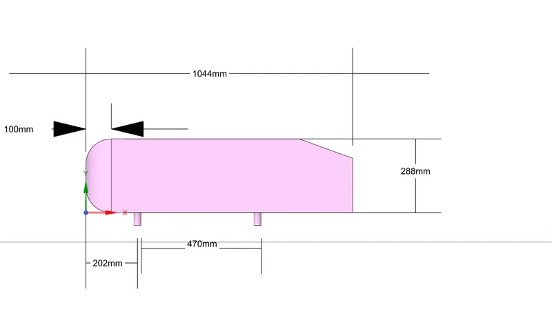
Geometry :
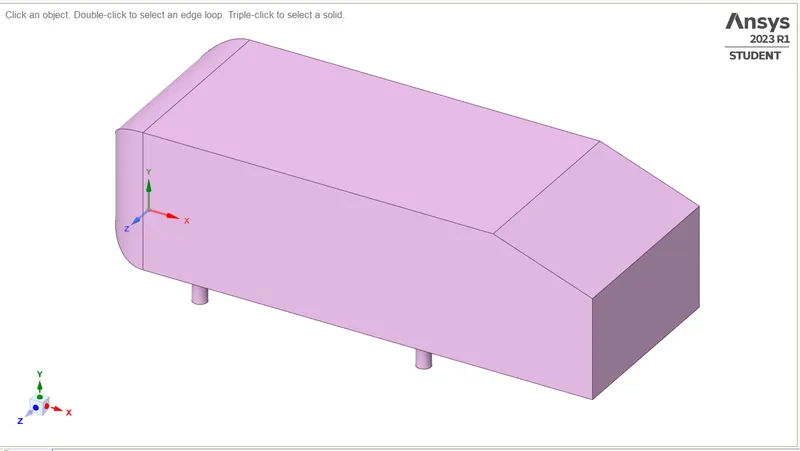
Body after enclosure :
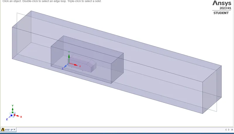
- An enclosure is a solid around a body or bodies that has a cushion around the enclosed solid(s). Box enclosure has been made to create an environment for fluid to flow over the ahmed body. The dimension of the enclosure is 2 meter towards left from the front side of the ahmed body and 5 meter towards right from the rear end of the body and again 1m from the top towards up and at bottom 0 meter.
- For sides 0.5 meter is given in either sides.
- Another enclosure is made inside the previous one to reuce the computational time and to capture physics effectively near the walls and in the wake region.
- The dimension of this enclosure is calculated from the base line simulation with respect to the wake region which is 0.5 meter towards left from the front side of the ahmed body and 1 meter towards right from the rear end of the body and again 0.5m from te top towards up and at bottom 0 meter.
- Enclosures are used to simulate fluid.
After spliting the body :
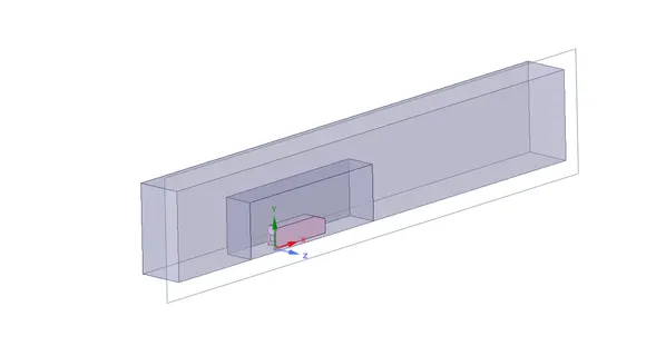
- Though the body is symmetry we cut the body into half in order to reduce the number of elements.
- Then uncheck the ahmed body and suppress for physics since we are concentrating physics at the outer side of the ahmed body.
- Then we check for the interferance inorder to avoid the mesh overlap and share the topology.
Mesh :
Mesh independent study :
The K-epsilon turbulence model with varied mesh refinement is used to perform mesh dependent study. The drag coefficient obtained from these case studies though vary in second decimal places but accounts significant for error percentage. It is obvious to have more accurate results with mesh refinement. In drag analysis it is important to have more refined mesh at external surface and in the wake region to capture pressure and viscous effects. Though the case studies shows negligible variation but in terms of drag coeffcient such variation is unfruitful (completely changes the definition of the external body). The study performed can be asserted as "Mesh dependent study", as the approximation varies significantly as a function of mesh refinement.
Case 1 :
Mesh Details :
| Enclosure 1 Mesh Method | Multizone | Element size = 110 mm |
| Enclosure 2 | Sizing (Body sizing) | Element size = 60mm |
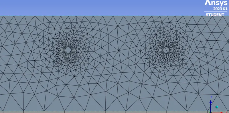
| Car-wall (Leg sizing) | Sizing (face sizing) | element size=5mm |
| Y value (Height of first cell centroid from the wall) | 2.8mm | y+ value=200 |
| Number of inflation layers | 5 | -- |
| Growth rate | 1.2 | -- |
| Inflation type | First layer thickness | 2.8mm |
| Total number of cells | 67967 |
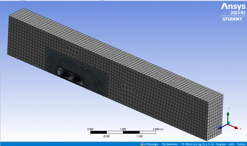
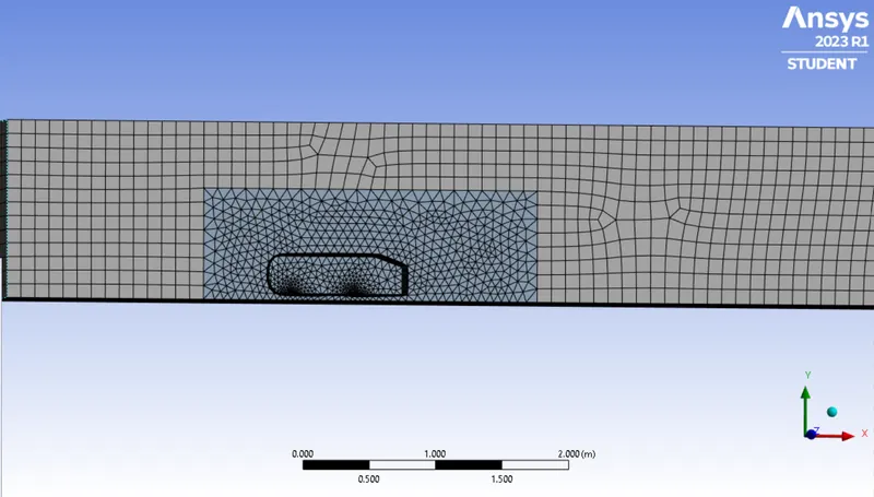
Ahmed body leg refinement :
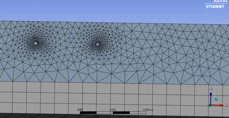
1.Naming the geometry as to inlet, outlet, carwall and symmetry.
2. Then using the multi-zone method for the outer encloser with an element size of 0.100m and max size 0.10m as well.
3. For the inner encloser use the body sizing of an element size of 0.05m
5. Then add inflation layer near the car-wall and choose 5 layers and provide total thickness of 0.0028
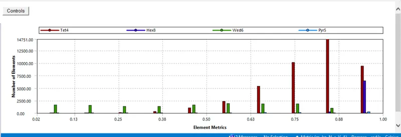
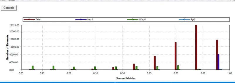
6. Finally check for the mesh quality.
Solution and Results :
Cases :
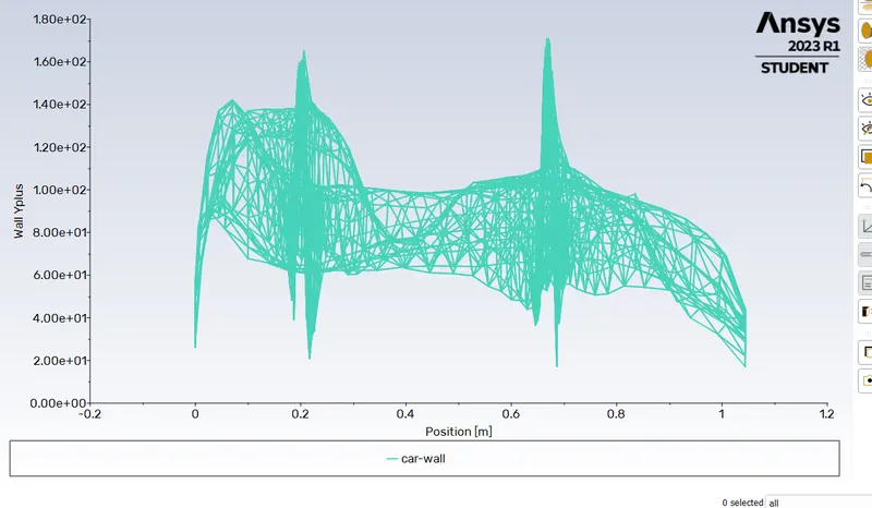
The simulation set-up will be using Y+ value of 200 and mesh with K-epsilon turbulence model. Steady-state analysis is performed
| Cases | Turbulence model | Mesh |
| Case 1 | K-epsilon (Realizable with Standard wall functions) | Coarse |
| Case 2 | K-epsilon (Realizable with Standard wall functions) | Medium |
| Case 3 | K-epsilon (Realizable with Standard wall functions) | Refined |
Why not k-omega as a turbulence model?
- The K-omega model is well suited for low Reynolds number which accounts for compressibility and shear flow spreading.
- However k-omega (SST-Shear Stress Transport) can be used in this case because of it's capability to incorporate high Reynolds number flows. As it uses K-omega in the inner region of the boundary layer and high Reynolds number model i.e K-epsilon in the outer region of the boundary layer.
- The mesh refinement is an important aspect in K-omega model as it accounts for near-wall effects. Mesh refinement should be much fine enough to capture near-wall effects. Accordingly, it uses extensive computation resources for such fine mesh refinement.
- Therefore it is better to opt for K-epsilon as it uses wall functions to estimate near-wall effects and is well suited for higher Reynolds number flows. Comparatively it is computationally cheap which can work with 30≤Y+≤200kgm.s. This certainly gives mesh refinement flexibility to compute near-wall effects.
|
SETUP |
||
|
Solver Type |
pressure - Based |
|
|
Velocity Formulation |
Absolute |
|
|
Time |
|
|
|
Viscous Model |
K-epsilon | |
|
Material |
Fluid type: Air |
|
|
Cell zones ff_surface |
Fluid type: Air | |
|
Boundaries |
Inlet (velocity inlet) Velocity Magnitude 25m/s Temperature – standard Outlet x (Pressure outlet) Gauge Pressure – 0 pa. Wall - wall Symmetry - symmetry |
|
|
Reference values |
Area = 0.065741 m^2 Density = 1.225kg/m^3 Enthalpy = 0 Jkg">J/kg Pressure = 0 pa Temperature = 288.16K Velocity = 25m/s Viscoity = 1.7894e-5">1.7894e−5 kg/m-s Length of the ahmed body(L_c) = 1.044m |
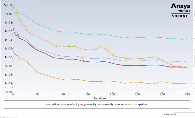
Residual plot :
Y+ Plot:
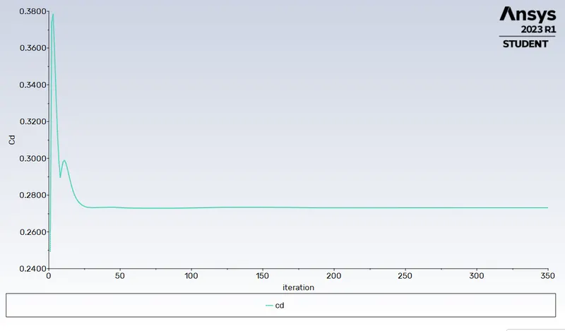
Drag co-efficient plot :
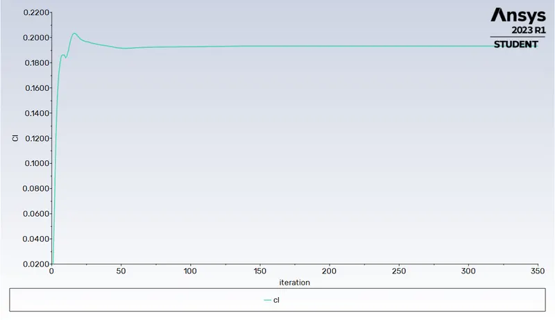
Lift co-efficient plot :
Velocity contour plot :
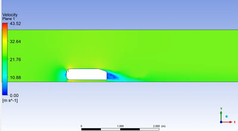
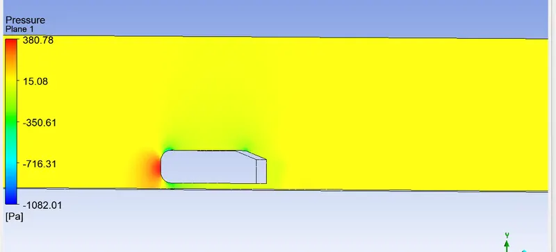
Pressure contour plot :
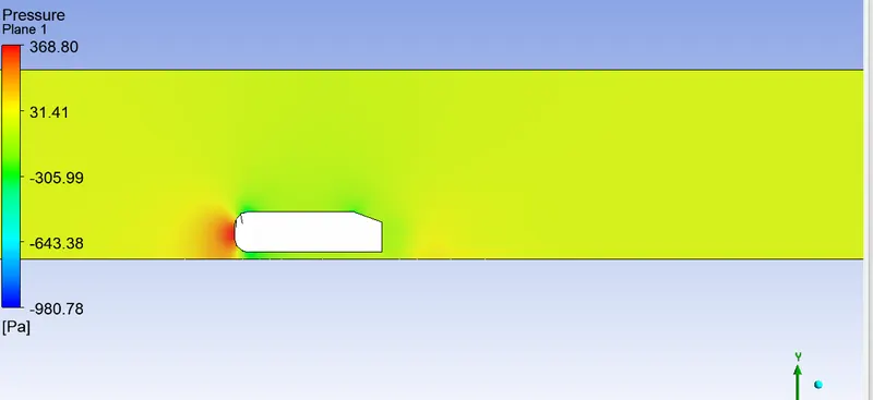
Velocity vector plot :
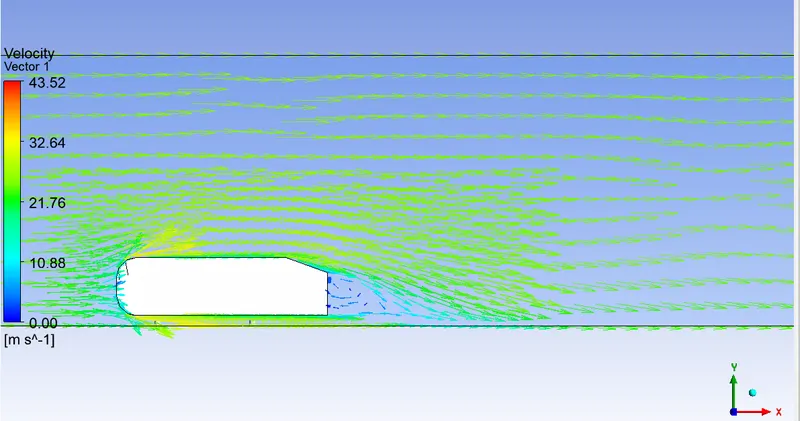
Velocity pathlines :
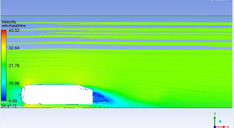
case 2:
Mesh Details :
| Enclosure 1 Mesh Method | Multizone | Element size = 100 mm |
| Enclosure 2 | Sizing (Body sizing) | Element size = 50mm |
| Car-wall (Leg sizing) | Sizing (face sizing) | element size=5mm |
| Y value (Height of first cell centroid from the wall) | 2.8mm | -- |
| Number of inflation layers | 5 | -- |
| Growth rate | 1.2 | -- |
| Inflation type | First layer thickness | 2.8mm |
| Total number of cells | 89795 |
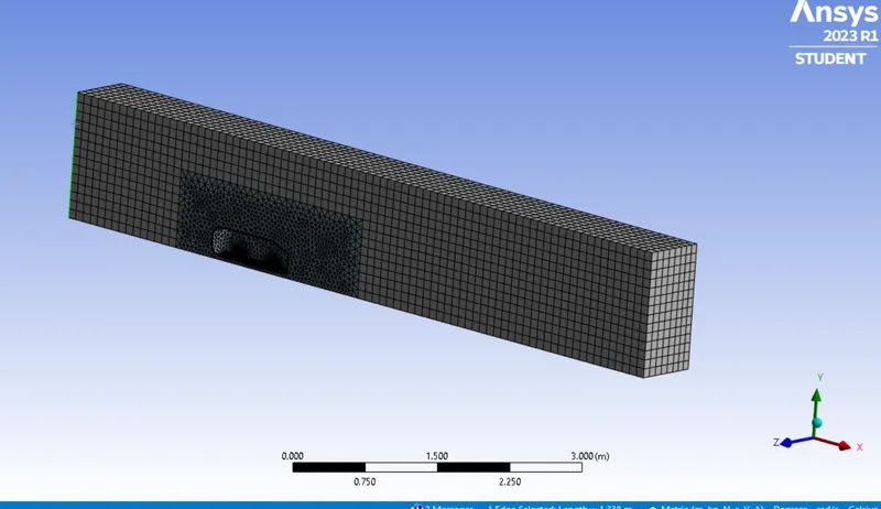
Inflation layer around ahmed body :
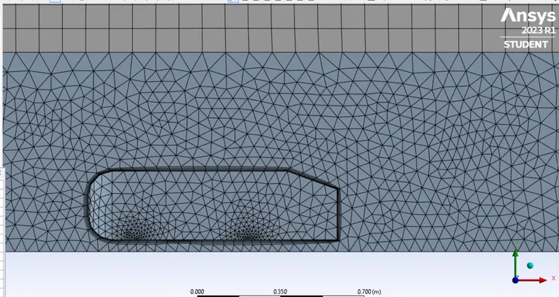
Ahmed body leg refinement :
Mesh quality :
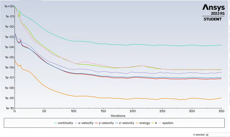
Residual plot :
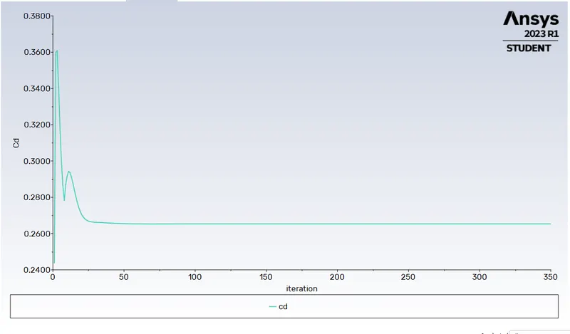
Drag co-efficient plot :
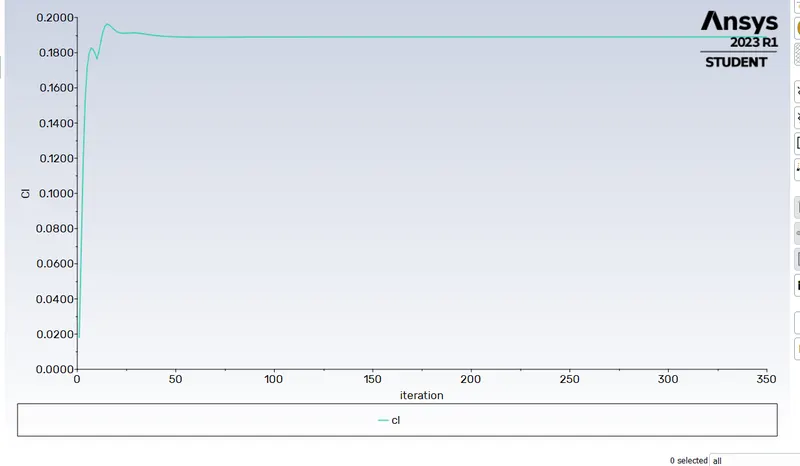
lift co-efficient plot :
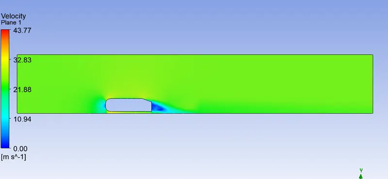
Velocity contour plot :
Pressure at the front side of the car :
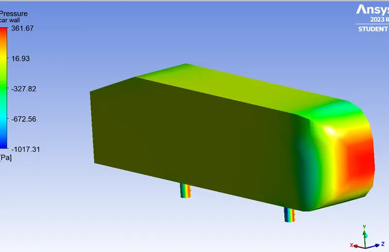
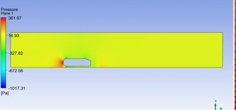
Pressure contour plot :
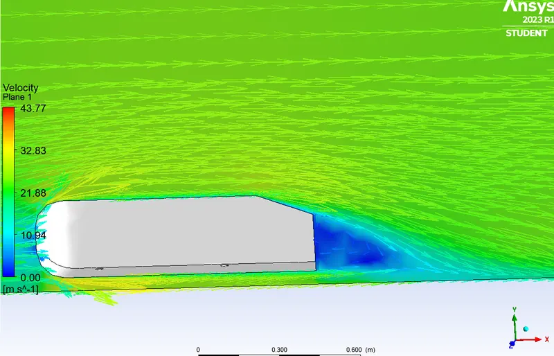
Velocity vector plot :
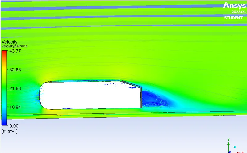
Velocity pathlines :
Case 3 :
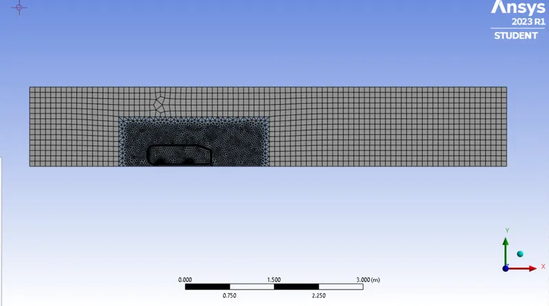
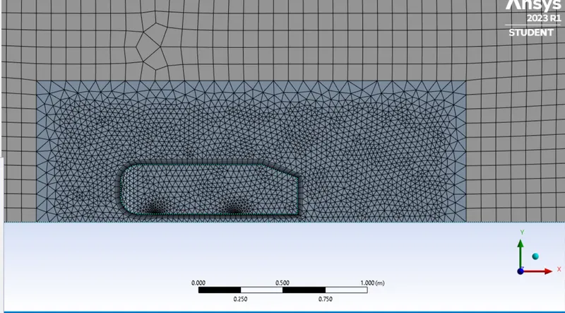
Mesh Details :
| Enclosure 1 Mesh Method | Multizone | Element size =90 mm |
| Enclosure 2 | Sizing (Body sizing) | Element size = 30mm |
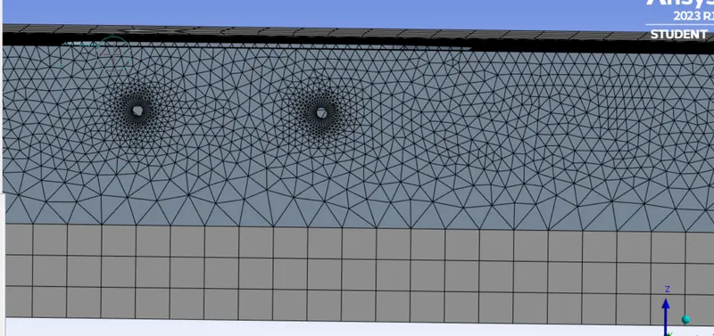
| Car-wall (Leg sizing) | Sizing (Edge sizing) | element size=3mm |
| Y value (Height of first cell centroid from the wall) | 3.5mm | -- |
| Number of inflation layers | 6 | -- |
| Growth rate | 1.2 | -- |
| Inflation type | First layer thickness | 3.5 mm |
| Total number of cells | 287304 | Refined |
Mesh quality :
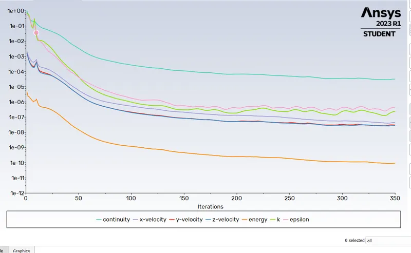
Residual plot :
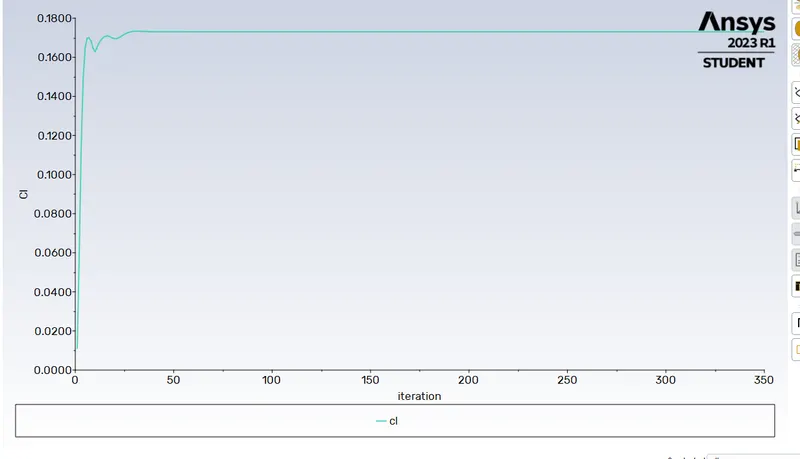
Lift co-efficient plot :
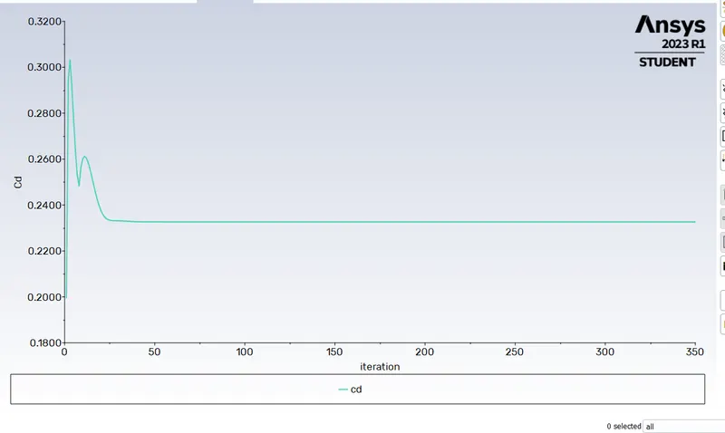
Drag co-efficient plot :
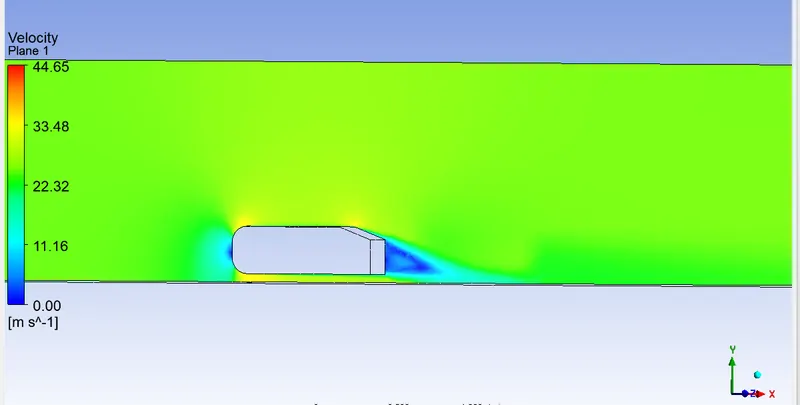
Velocity contour plot :
Pressure contour plot :
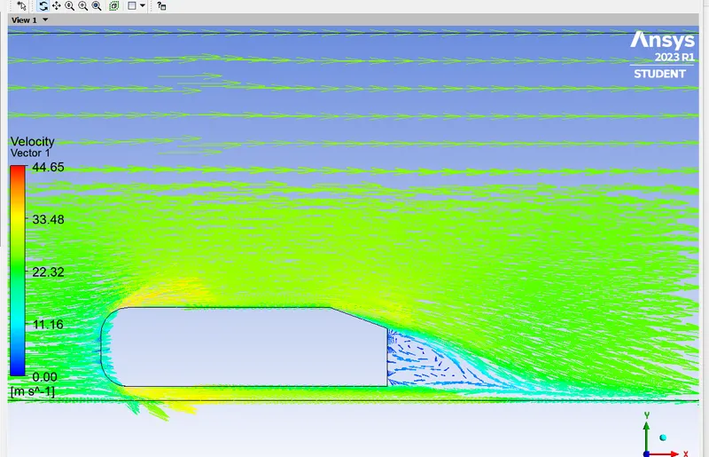
Velocity vector plot :
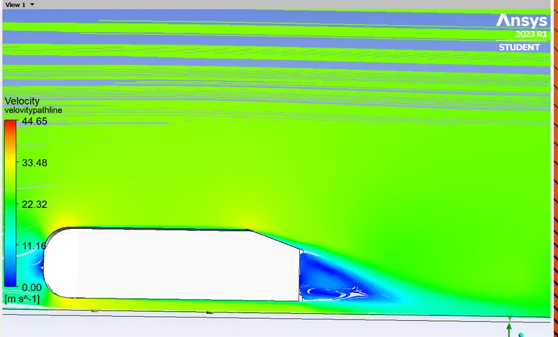
Velocity pathlines :
Comparison of all cases :
| Steady-state, Turbulent flow, pressure-based, Fluid material -Air | |||||
| Grid Independence Test | Number of elements | Type of mesh | No of inflation layers | Lift-Coefficient | Drag-Coefficient |
| Case 1 | 67967 | Coarse | 5 |
0.1932 |
0.2731 |
| Case 2 | 89795 | Medium | 5 | 0.1825 | 0.26 |
| Case 3 | 287304 | Refined | 6 |
0.1730 |
0.2326 |
The standard reference of drag coefficient is given as below 0.33. The resulting numerical solution is close agreement with the standard reference.
Numerical error :
Conclusion :
- High pressure is formed at the frontal area of the Ahmed body due to the loss of kinetic energy of the air.
- When the airflow experiences sudden geometrical changes (slant length), it will start to detach from the surface of the body. This will subsequently lead to formation of eddies and region of recirculation immediate behind the body. It represents wake region which accounts for low pressure distribution behind the body causing imbalance in the net pressure distribution. The low pressure region will be obtained from flow separation due to adverse pressure gradients.This wake region holds the car body from behind and hence restricts the motion of the body which in turn affects the drag and lift coefficients .