Week 3 - External flow simulation over an Ahmed body.
External flow simulation over an Ahmed body
AIM:
- Describe Ahmed's body and its importance.
- Explain the reason for the negative pressure in the wake region.
- Explain the significance of the point of separation.
INTRODUCTION:
The pollution emerged by using volatile fuels in automobile has become a major concern pertaining to the environment and economic viability. Different approaches such as improving the efficiency or usage of alternative fuels for the vehicle have been considered. Advancement in some of the major areas such as aerodynamics improvement, weight reduction and power increase has given us many feasible results, but reducing aerodynamic factors such as drag, lift is more efficient than increasing the power of the vehicle or decreasing the weight of the vehicle.
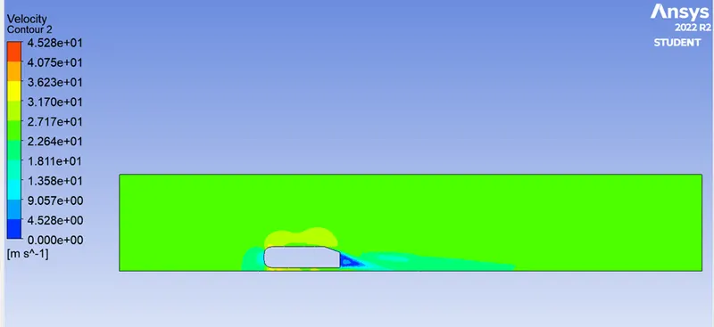
Air has a tendency to curl downwards around the ends of a car, travelling upwards from the high-pressure region under the car to the low-pressure region on top, at the rear end of the automobile and subsequently collides with moving low-pressure air. The kinetic energy of these turbulent air spirals acts in a direction that is negative relative to the direction of travel intended. Thus, the car engine must compensate for the losses created by this drag. Vortices are released during flow separation and trail downstream to form structured or unstructured wake patterns. A wake is the region of re-circulating flow immediately behind a moving or stationary solid body, caused by the flow of surrounding fluid around the body. The local disturbances in the flow pattern behind the vehicle causes a momentum loss thus causing form drag which extends far behind the bodyworks of a vehicle.
Importance of Ahmed Body:
The generic Ahmed Body reference model has been chosen as the benchmark for carrying out computations for studying of the aerodynamic parameters. The body was first proposed by Ahmed et al., (1984). The Ahmed body is a very simple bluff body which has its shape simple enough to allow for accurate flow simulation but retains some important practical features relevant to automobile bodies. It has a slant on its rear end, whose angle can be manipulated and the corresponding drag and lift coefficients calculated. This is done to exhibit the air flow over the different geometry sections of an automobile and in its vicinity, at different slant angles. This model portrays how to calculate the turbulent flow field around a simple car-like geometry using the turbulent flow, k-epsilon interface. Once the numerical model in validated, it is used to design new models of the car.
The reason for the negative pressure in the wake region
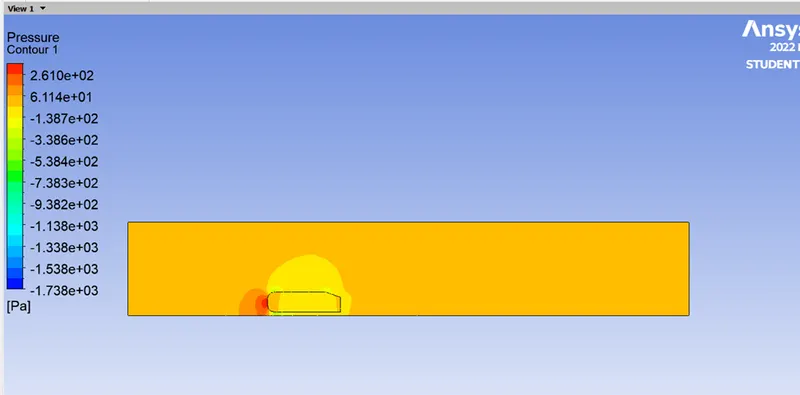
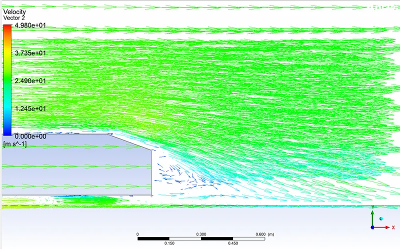
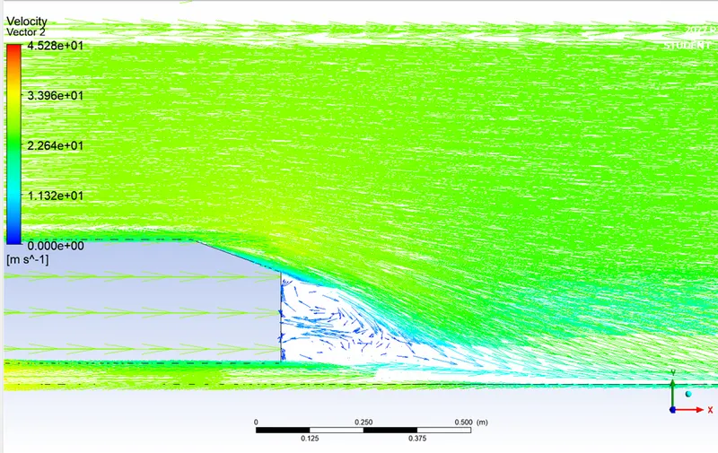
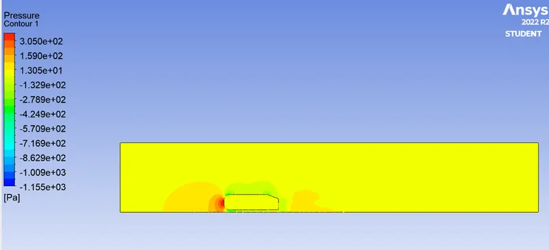
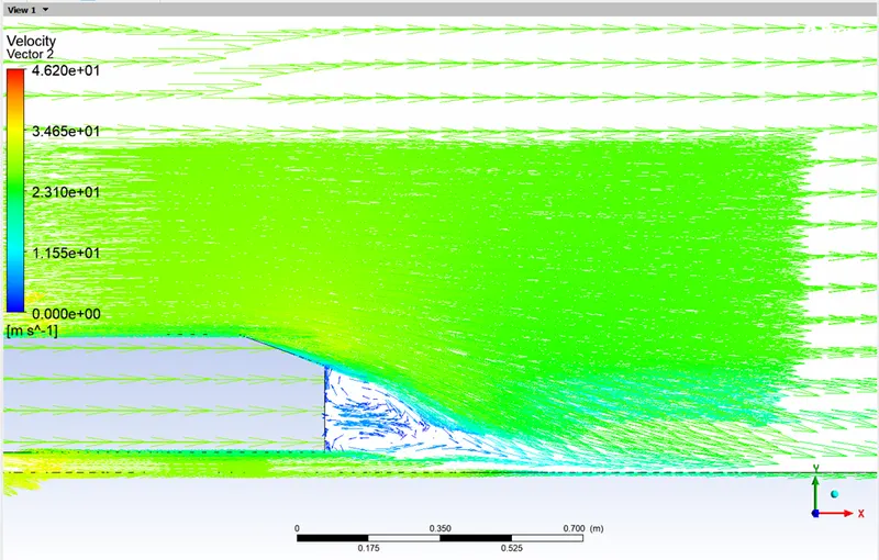
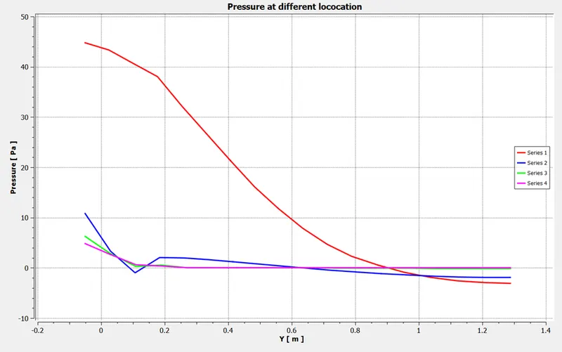
The flow behind an object separates from the surface and creates a highly turbulent region behind the object, called the wake. The pressure inside the wake region remains low as the flow separates and a net pressure force (pressure drag) is produced. We have two regions behind the vehicle moving in -ve x-direction: (a)Wake region and (b) the core flow (in the +ve x-direction) adjacent to the wake region where the fluid particles are moving with high velocity. Since the core region particles are moving at high velocities, the pressure is low in that region. However, in the wake region, we have vacuum pressure i.e., relatively much lower pressure. After flow separation after a certain distance, the fluid particles get into the wake region and try to rush towards the rear surface of the vehicle. The particles near the rear surface may either be moving upwards or otherwise curved towards the +ve x-direction. If we draw the streamlines near the rear surface of the vehicle, we can observe that the x-velocity component can either be zero or in the +ve x-direction only. Hence, the resultant force can be either zero or a drag force.
The significance of the point of separation
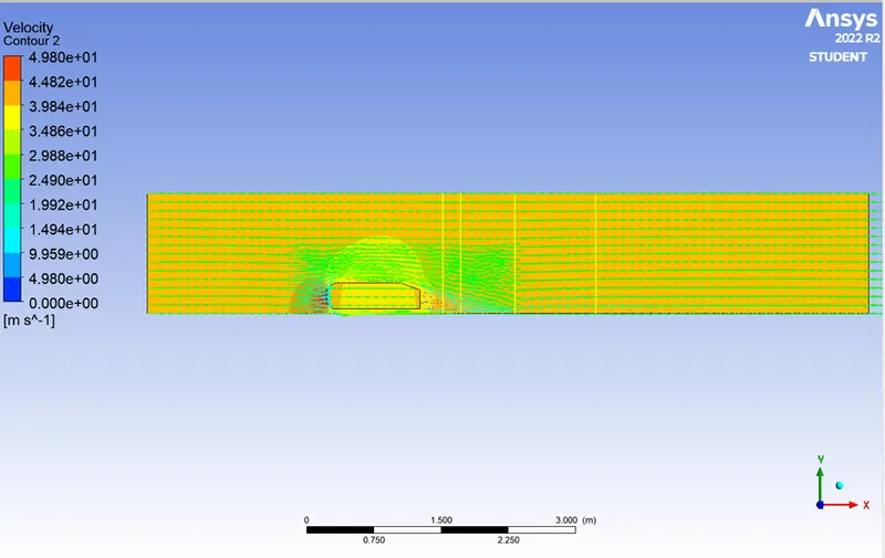
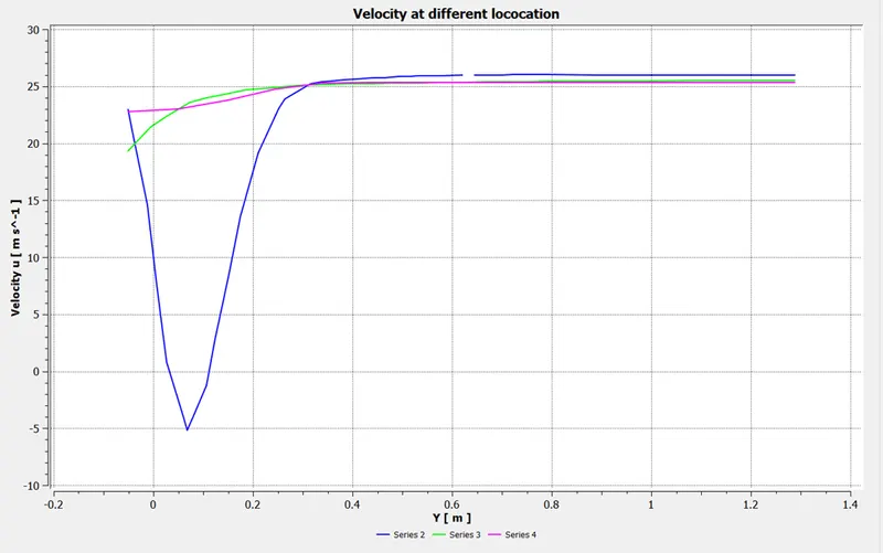
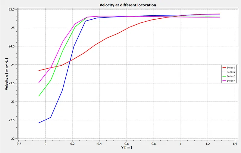
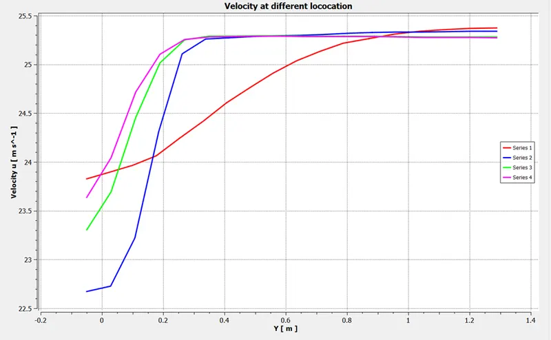
The fluid separation point can be defined as a point where the dv/dy i.e., gradient of velocity goes zero along with the dp/dx = 0, for the specific point. In more simplified term we can say that the point where the velocity gradient goes zero and the pressure gradient along the x- direction goes zero the point of separations starts occurring or the negative pressure gradient starts forming after that point. The point of separation cannot be understood just by single contour in hard and fast way. It can be supportively studied with the help of the dp/dx plots or velocity plots w.r.t the Y direction and other such plots in which we can see the nature of such physical properties like dp/dx=0, and dv/dy=0 experiencing in a particular region of fluid and body interaction.
Geometry of Ahmed Body:
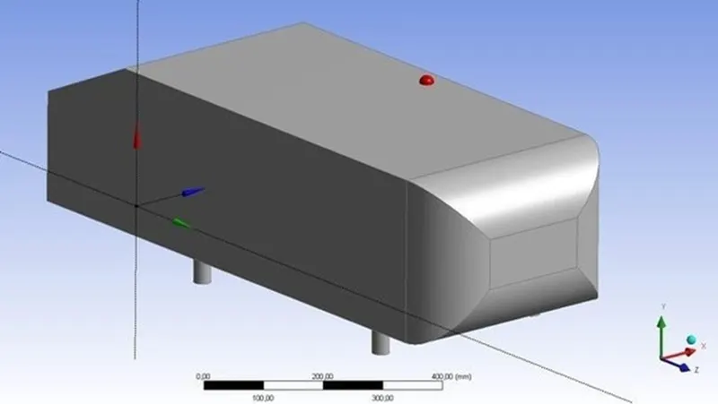
The above image shows the Model of Ahmed Body.
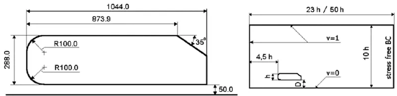
The detailed dimensions for creation of Ahmed Body Model.
Procedure for simulation of Ahmed Body:
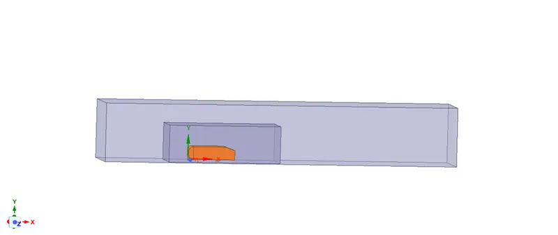
- Creating the Geometry using Ahmed Body Model through spaceclaim. Allowing/Creating the box for simulation of velocity & pressure effect in certain distance from vehicle or Ahmed Body.
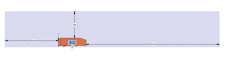
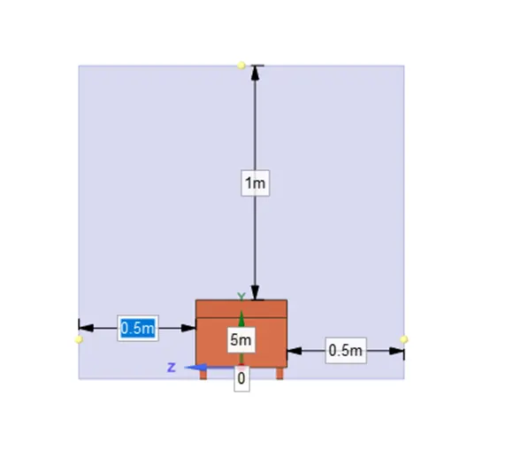
Meshing:
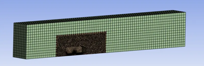
The geometry which is created in spaceclaim will be meshed in mesh function/section.
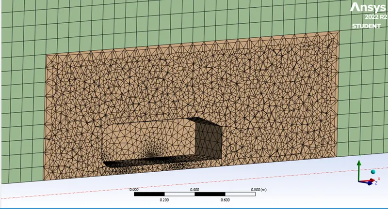
Outer enclosure: 0.1m (elemental mesh size)
inner enclosure: 0.05m (elemental mesh size)
Face sizing for Ahmed body: 0.005m (elemental mesh size)
Without inflation layer with case mesh.
The below image shows the Fully meshed Body/Model of Ahmed Body.
SETUP AND POST PROCESSING OF AHMED BODY:
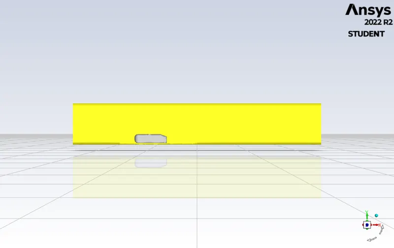
Setting up the meshed body in setup section by applying velocity at inlet face, selecting the default air material with its default density and dynamic viscosity.
Creating the Drag & Lift coefficient for modified Ahmed Body and at reference value allowing start from inlet with certain area, length, velocity etc. details.
Refined Ahmed Body
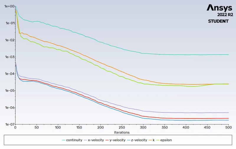
RESIDUAL PLOT:
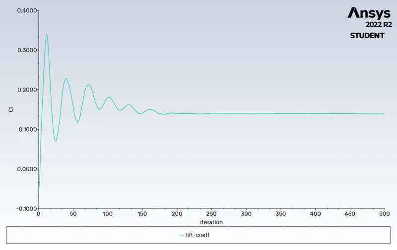
LIFT COEFFICEIENT:
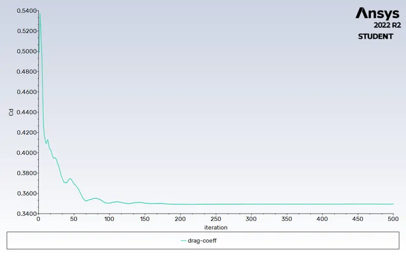
DRAG COEFFICIENT:
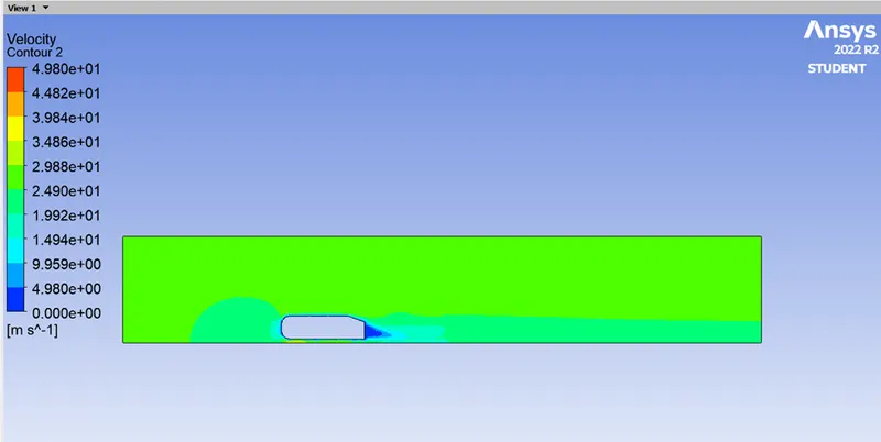
VELOCITY CONTOUR:
PRESSURE CONTOUR:
VECTOR AT WAKE REGION OF AHMED BODY:
SECTION LINE ON REFINED AHMED BODY:
VELOCITY PLOT AT DIFFERENT DISTANCE LENGTH OG MODEL:
CASE 2:
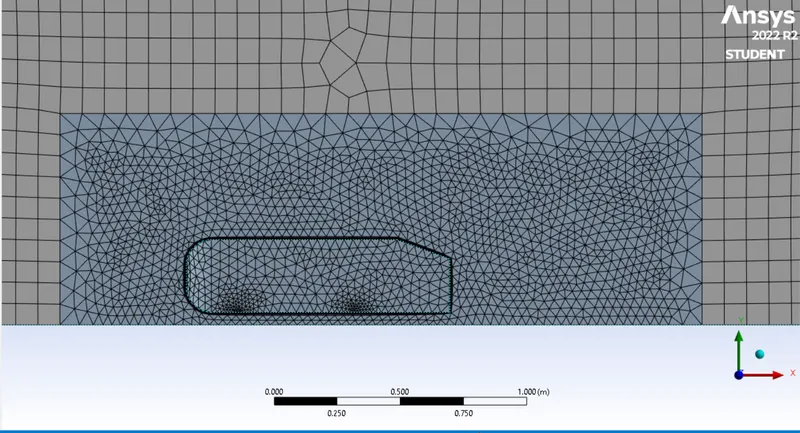
Outer enclosure: 0.09m (elemental mesh size)
inner enclosure: 0.035m (elemental mesh size)
Face sizing for Ahmed body: 0.005m (elemental mesh size)
inflation for Ahmed body: 5 Layer with a total thickness of 12.4mm
i.e., first layer thickness distance is about 1:2.
Therefore, total thickness is calculated as Total Thickness = size of mesh * distance between layers ^ (No. of layers)
i.e. Total Thickness = 5*1.2^5 = 12.4 ≈ 12.5
FEFINED MESH:
RESIDUAL PLOT:
LIFT COEFFICIENT:
DRAG COEFFICIENT:
PRESSURE CONTOUR:
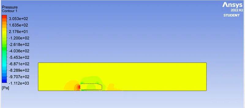
VELOCITY CONTOUR:
VECTOR AT WAKE REGION OF AHMED BODY:
VELOCITY PLOT AT DIFFERENT DISTANCE LENGTH OG MODEL:
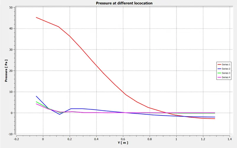
PRESSURE PLOT AT DIFFERENT DISTANCE LENGTH OG MODEL:
CASE 3:
Outer enclosure: 0.08m (elemental mesh size)
inner enclosure: 0.03m (elemental mesh size)
Face sizing for Ahmed body: 0.005m (elemental mesh size)
inflation for Ahmed body:5 Layer with a total thickness of 12.4mm
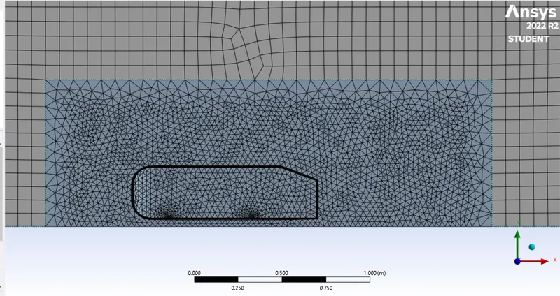
REFINED MESH:
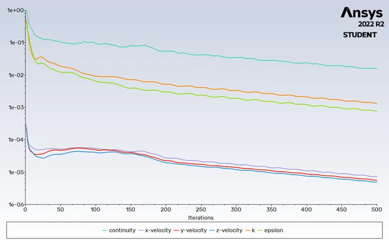
RESIDUAL PLOT:
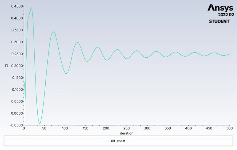
LIFT COEFFICIENT:
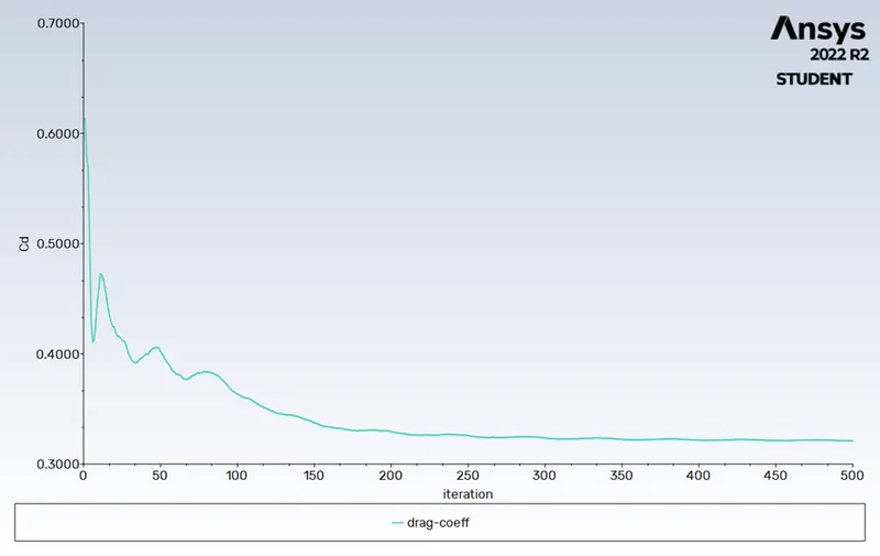
DRAG COEFFICIENT:
PRESSURE CONTOUR:
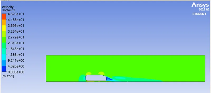
VELOCITY CONTOUR:
VECTOR AT WAKE SIDE OF AHMED BODY:
PRESSURE PLOT AT DIFFERENT DISTANCE LENGTH OG MODEL:
VELOCITY PLOT AT DIFFERENT DISTANCE LENGTH OF MODEL:
Grid Dependence Test & Results:
|
Number of cells |
Drag-coefficient (Cd) |
Lift-coefficient (Cl) |
|
|
Case 1 |
84452 |
0.349 |
0.139 |
|
Case 2 |
188825 |
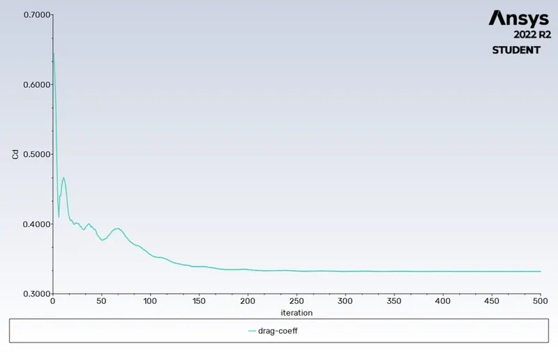
0.331 |
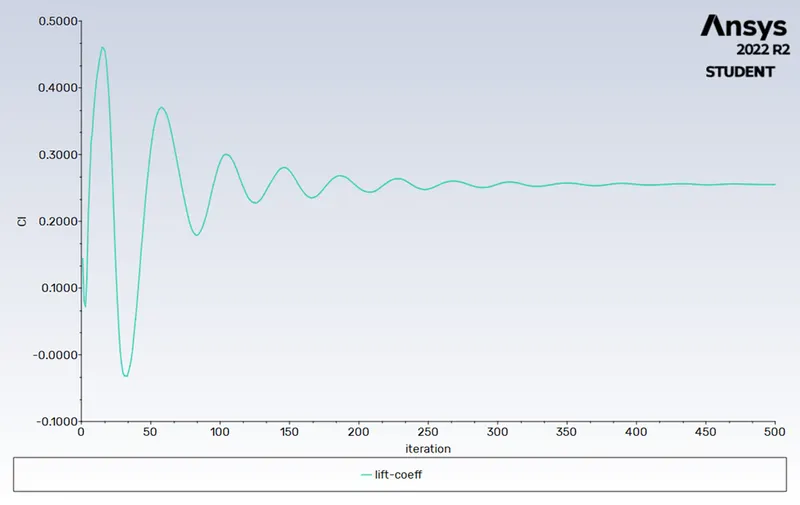
0.255 |
|
Case 3 |
286198 |
0.321 |
0.250 |
|
Case 4 (k-omega, SST ) at same mesh size case 3 |
286198 |
0.317 |
0.236 |
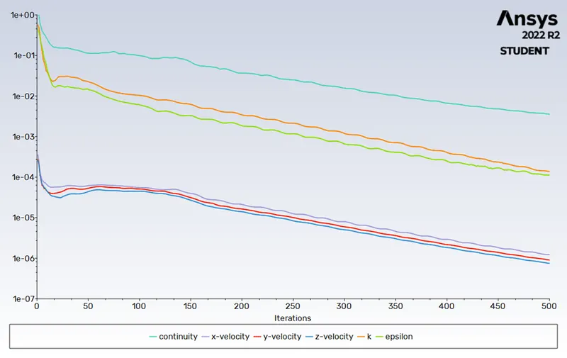
From the above table with the refinement of the mesh drag coefficient approaches closer to the analytical values that are because more cells are produced at the boundary layer which results in more accurate results of drag coefficients.
CONCLUSION:
Grid Dependence Test was conducted and the test was successful, an additional observation was also made - the drag coefficient decreases as number of elements increases. This decrease is very small and may be considered insignificant.
The cause of flow separation in the fluid flow is because of negative pressure generation in the boundary layer of flow near wall of body and negative wake region is generated due to the pressure difference between low stream and high stream flow also due to flow separations.
REFERENCES:
https://www.researchgate.net/post/Why_the_pressure_is_negative_in_wake_region_behind_the_vehicle