Week 3 - External flow simulation over an Ahmed body.
Aim:
Simulate the flow over Ahmed's body and use air as the working fluid with a velocity of 25 m/s.
Theory :
The Ahmed body is a generic car body with a simplified vehicle model. The airflow around the Ahmed's body captures the aerodynamic flow to check the flow pattern and was first defined and characterized in the experimental work of Ahmed [1]. Although it has a very simple shape, Ahmed's body allows us to capture characteristic features that are relevant to bodies in the automobile industry.
This model is also used to describe the turbulent flow field around a car-like geometry. Once the numerical model is invalidated, it is used to design new models of the car.
Geometry
This is the sketch drawing:
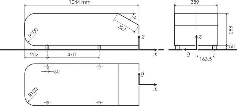
The angle of the bend is 20 degrees. I imported a . STEP file for this project in Space Claim.
This is the geometry after the splitting:
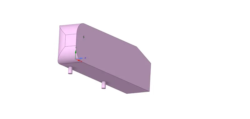
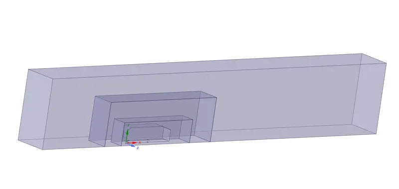
An enclosure has been created around Ahmed's body The inlet of the wind tunnel is 2 meters from the front of Ahmed's body, the outlet is 5 meters from the back of the body. The height of the enclosure is 1 meter above the Ahmed body while the width is 0.5m from the side of the body. The enclosure is checked for Interference and it is repaired as well.
Further enclosures may be created for mesh refinement.
This is the final geometry with three enclosures:
Meshing
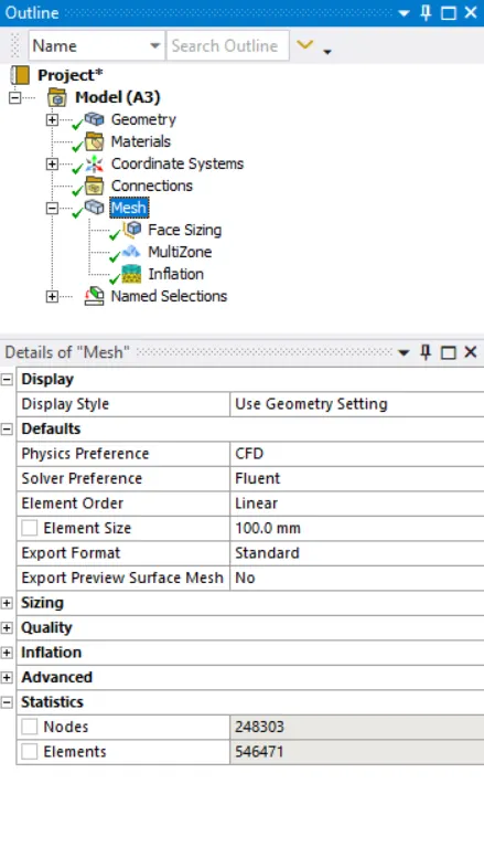
The base size is 0.1m. There are multiple mesh controls used to generate the mesh for this geometry, they are:
Base Mesh:
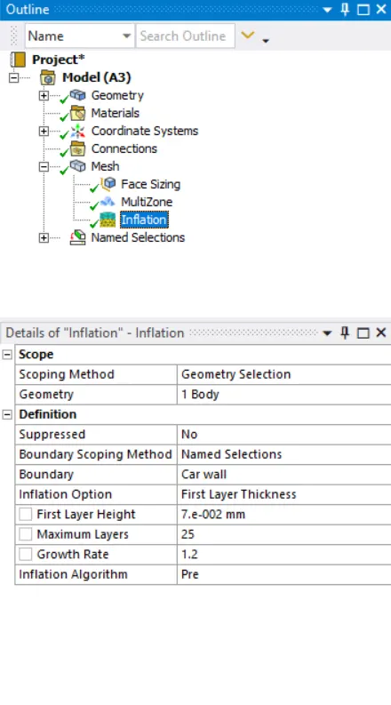
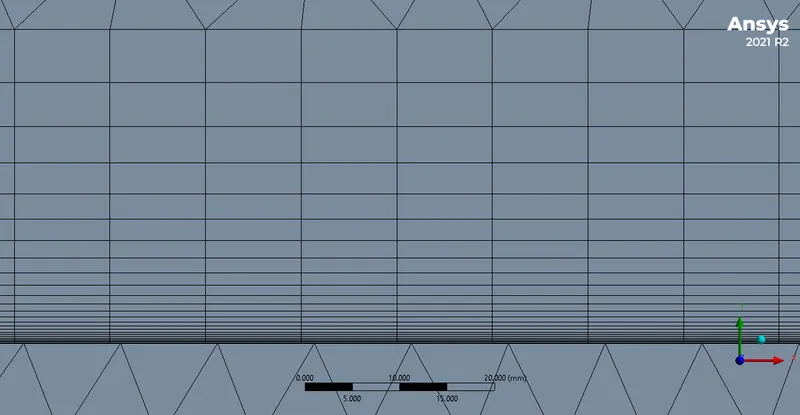
1. Mesh -> Inflation
This option is used to accurately capture the boundary layers on the surface of the body.
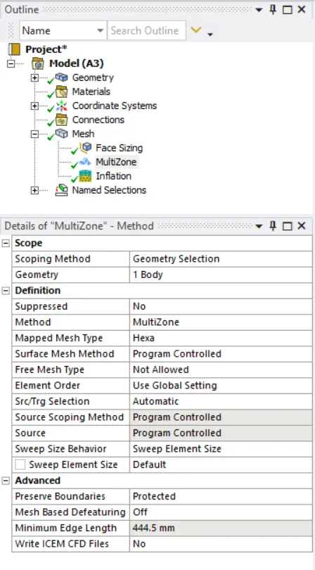
2. Method -> Multizone
This option is used to generate mesh in the outer region which is primarily hexahedral
3. Sizing -> Body Sizing
This option is used to refine the larger inner enclosure of the wind tunnel. The increased size gives us more accurate results near the Ahmed's body. The element size is 100m.
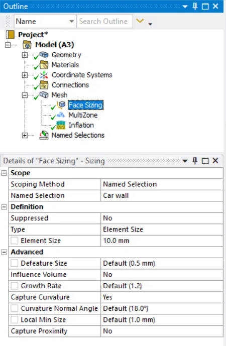
4. Sizing -> Face Sizing
This method is used to ensure that the legs of the ahmed body are circular and not polyhedral.
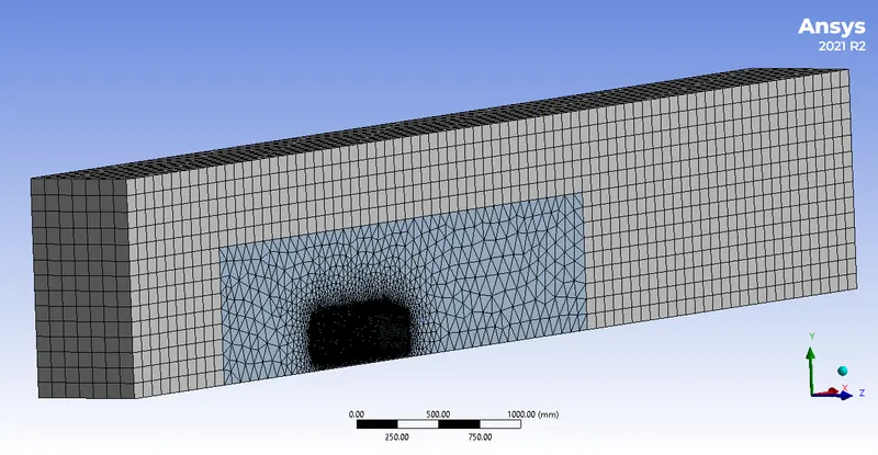
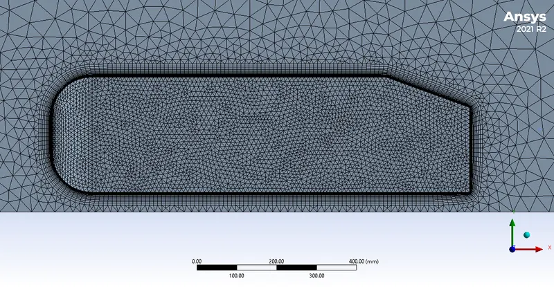
After all these controls are applied, this is the resultant base mesh:
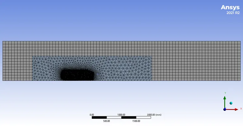
Zooming in,
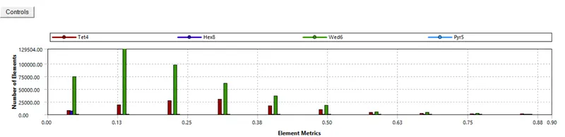
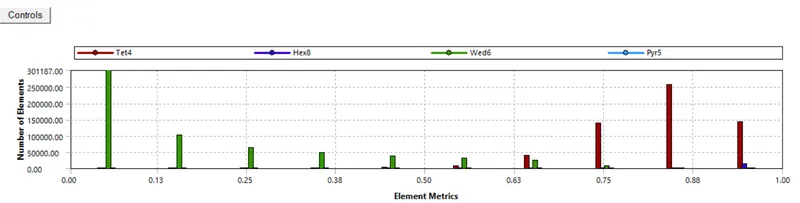
These are the mesh metrics:
Fine Mesh:
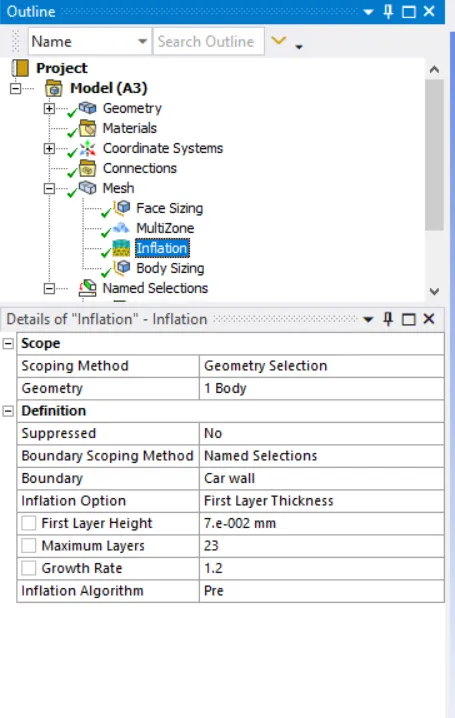
1. Mesh -> Inflation
This option is used to accurately capture the boundary layers on the surface of the body.
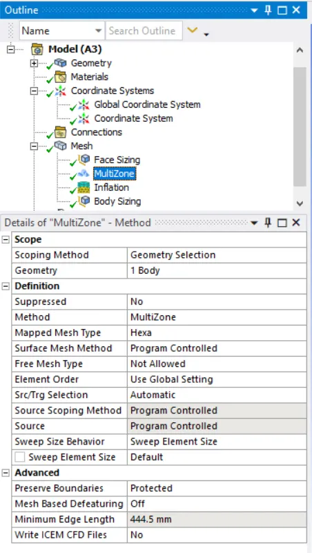
2. Method -> Multizone
This option is used to generate mesh in the outer region which is primarily hexahedral
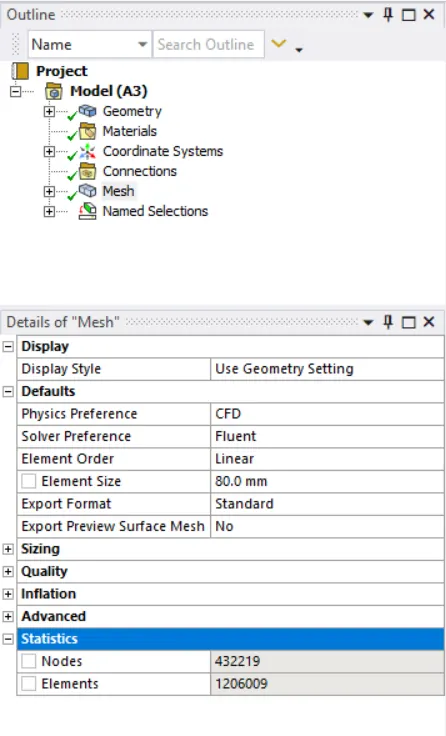
3. Sizing -> Body Sizing
This option is used to refine the larger inner enclosure of the wind tunnel. The increased size gives us more accurate results near the Ahmed's body. The element size is 100m.
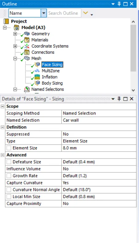
4. Sizing -> Face Sizing
This method is used to ensure that the legs of the ahmed body are circular and not polyhedral.
After all these controls are applied, this is the resultant base mesh:
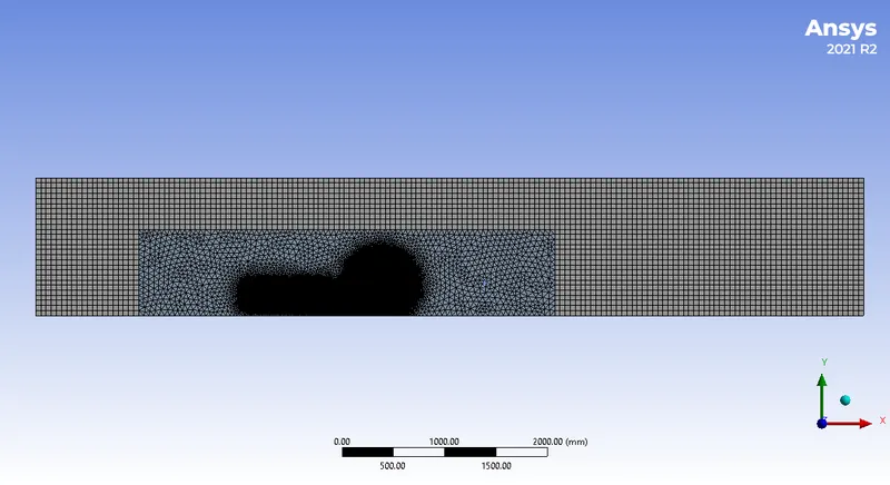
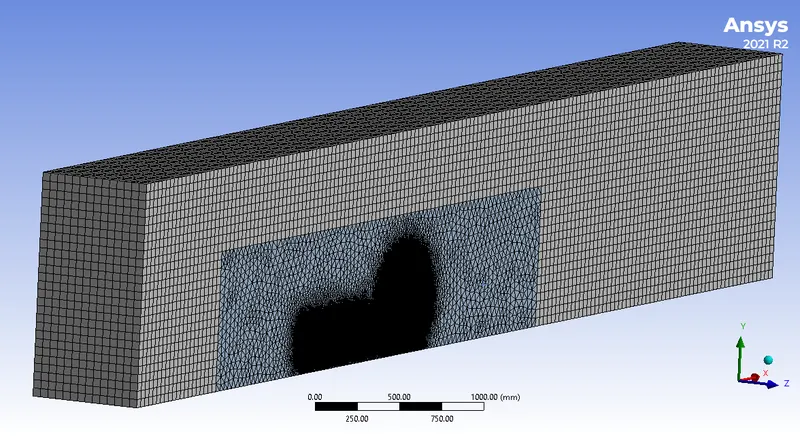
Zooming in,
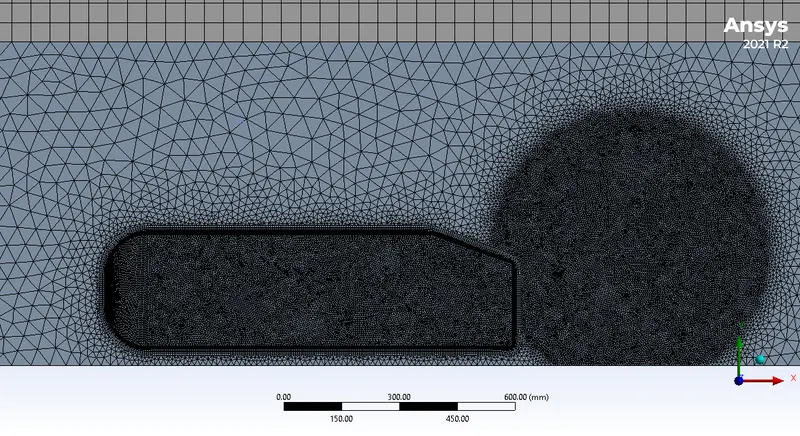
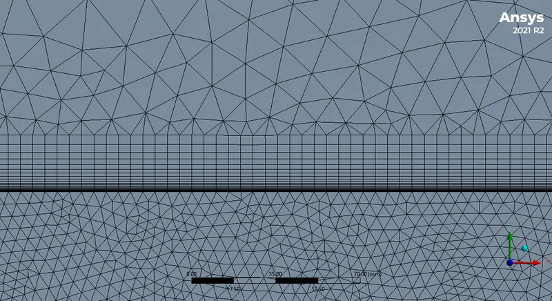
These are the mesh metrics:
Setup
Boundaries
inlet - inlet
outlet - pressure outlet
wall-car - wall (no-slip)
back, top, and bottom - symmetry
A separate boundary was created for the symmetry plane to make post-processing easier.
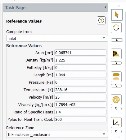
Reference Values
The most important values here are Area, Density, Length, and Velocity.
Viscous
k-omega SST was used for all simulations for this project due to its excellence in solving external flows and wake regions.
Reports
Two reports were created.
1. Lift Coefficient of wall-car
2. Drag Coefficient of wall-car
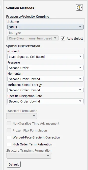
Solution - Methods
Simulation of the base setup
Base Mesh:
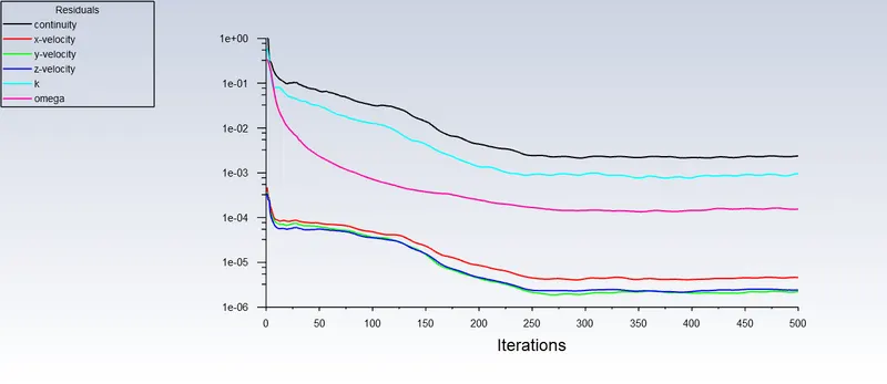
The simulation ran for 500 iterations and the results are below:
Residuals
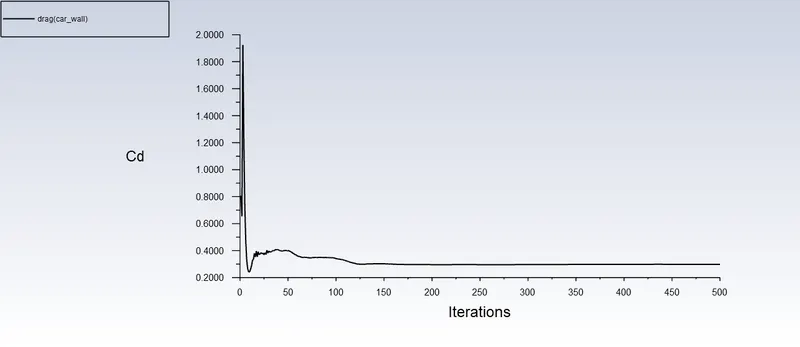
Drag Coefficient
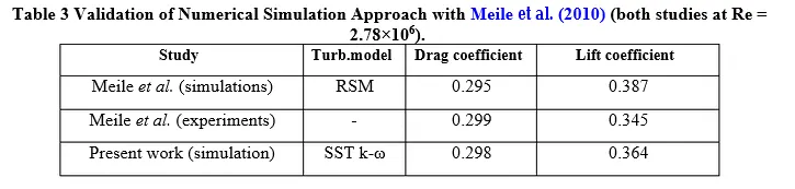
The final value of the drag coefficient is 0.29837966, which is in agreement with experimental and simulation data.
This data is from Moghimi et al. [1]
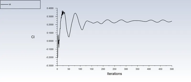
Lift Coefficient
The final value of the lift coefficient is 0.24246156, the discrepancy is due to variation in Reynolds number and low mesh resolution near some regions of the Ahmed body.
Contours, Plots, and Vectors
Note: All plots, contours, and vectors were obtained from the finer mesh, due to its higher solution clarity.
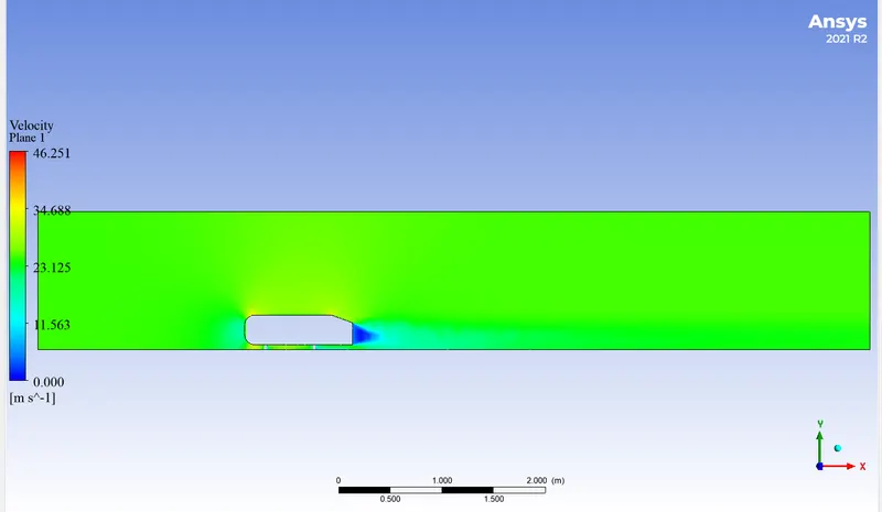
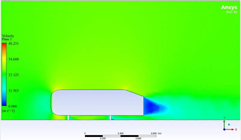
1. Velocity contours
These were taken in CFD - Post.
Zooming in,
Zooming in further,
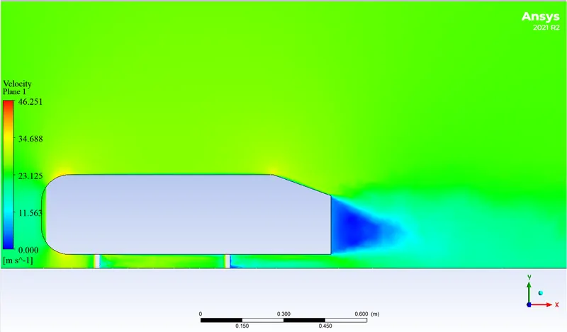
The wake is clearly visible.
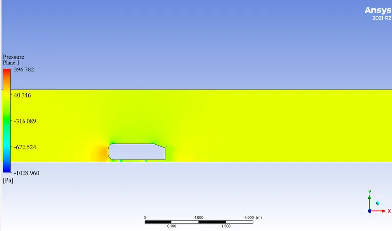
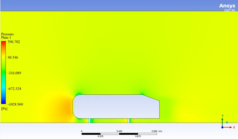
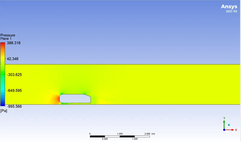
2. Pressure Contour
These were taken in CFD - Post.
Zooming in,
Fine Mesh:
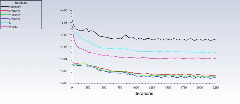
The simulation ran for 2250 iterations and the results are below:
Residuals
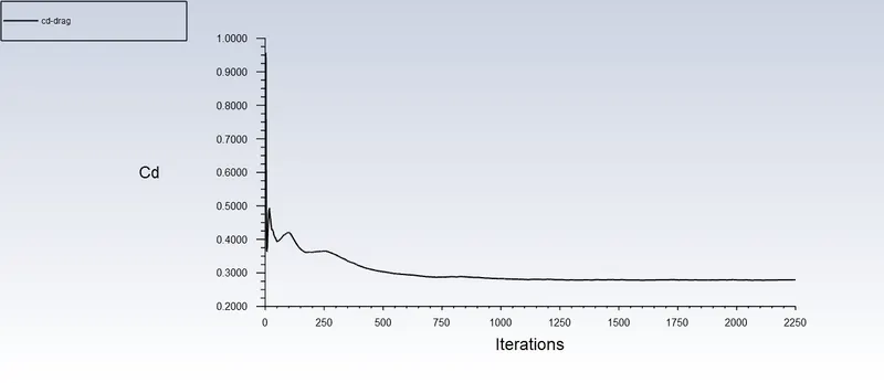
Drag Coefficient
The final value of the drag coefficient is 0.29837966, which is in agreement with experimental and simulation data.
This data is from Moghimi et al. []
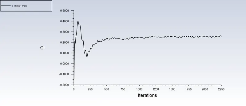
Lift Coefficient
The final value of the lift coefficient is 0.24246156, the discrepancy is due to variation in Reynolds number and low mesh resolution near some regions of the Ahmed body.
Contours, Plots, and Vectors
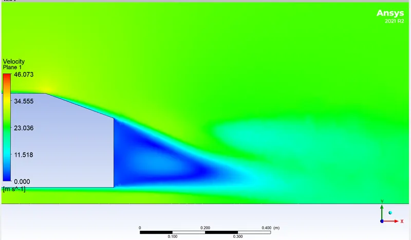
1. Velocity contours
These were taken in CFD - Post.
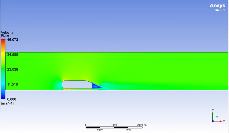
Zooming in,
Zooming in further,
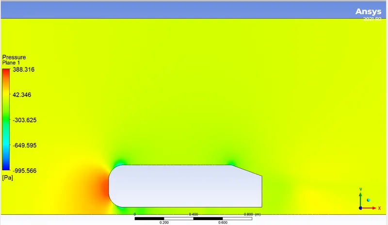
2. Pressure Contour
These were taken in CFD - Post.
Zooming in,
3. Vector Plot
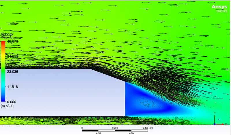
Zooming in,
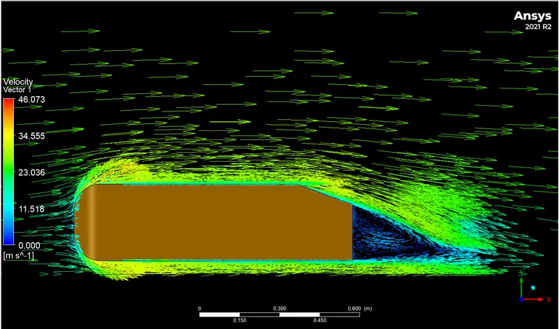
Zooming in further near the wake region,
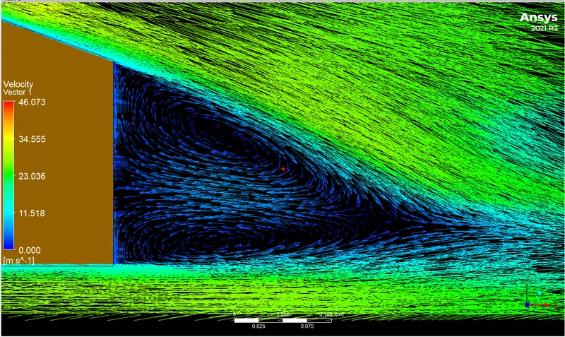
Summary of Grid Dependence Test
| Lift Coefficient | Drag Coefficient | Nodes | Elements | |
| Coarser Mesh | 0.22592755 | 0.35537949 | 37033 | 104163 |
| Base Mesh | 0.24246156 | 0.29837966 | 248303 | 546471 |
| Finer Mesh | 0.2530714 | 0.2792628 | 432219 | 1210101 |
Drag coefficient decreases as the number of elements increases, this claim is substantiated by the work of Jie Tian et al [3]
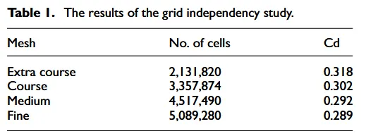
The important takeaway is that drag coefficient does not vary significantly when the mesh is made finer. While the drag coefficient does vary when the mesh is made more coarse. This means that the grid dependence test has passed.
Conclusion and Observations
1) The aerodynamic flow over Ahmed's body was simulated successfully with three different types of meshes. Which resulted in validation with experimental data with reference open literature.
2) The angle between the bend is 20 degrees and the region at the back side where the wake region is formed with a low velocity which resulted in induced drag to the Ahmed body.
3) By [4] the experimental data was validated with the present simulation. the value of the drag coefficient of the simulation was also validated with [5].
4)Grid Dependence Test was conducted and the test was successful, an additional observation was also made - the drag coefficient decreases as a number of elements increases. This decrease is very small and may be considered insignificant.
References
[1] S.R. Ahmed, G. Ramm, Some Salient Features of the Time-Averaged Ground Vehicle Wake, SAE-Paper 840300, 1984
[2] Moghimi, Pouria & Rafee, Roohollah. (2018). Numerical and Experimental Investigations on Aerodynamic Behavior of the Ahmed Body Model with Different Diffuser Angles. Journal of Applied Fluid Mechanics. 11. 1101-1113. 10.29252/jafm.11.04.27923.
[3] 1. Tian J, Zhang Y, Zhu H, Xiao H. Aerodynamic drag reduction and flow control of Ahmed body with flaps. Advances in Mechanical Engineering. July 2017. doi:10.1177/1687814017711390
[4] Gilliéron, Patrick & F., Chometon. (1999). Modelling of stationary three-dimensional detached airflows around an Ahmed Reference Body.
[5]Meile, Walter & Brenn, Günter & Reppenhagen, Aaron & Lechner, Bernhard & Fuchs, Anton. (2011). Experiments and numerical simulations on the aerodynamics of the Ahmed body. CFD Letters. 3.