External flow simulation over an Ahmed body.
INTRODUCTION :-
The Ahmed body is simplified car body used in automotive field to study the impact of the flow pattern on the drag. The external aerodynamics of the car defines many major traits of an automobile like stability, comfort and fuel consumption at high speeds. The flow around the vehicle is characterized by high turbulent and three dimensional flow separations as well as there is a growing need for more insight into the physical features of these dynamical flows. The Ahmed Body is a simplified car, used in automotive field to investigate the flow analysis and find the wake flow around the body. Ahmed body is made up of round front part, a moveable z slant plane in the rear of the body to study the detachment phenomena at different angles, and a rectangular box which link the front part and the rear slant plane. The principal objective to study such a simplified car body is to tackle the flow processes involved in drag production. Through perceiving the mechanisms involved in creating drag one can be able to design a car to minimize drag and therefore reducing fuel consumption and maximize vehicle performance.
AHMED BODY :-
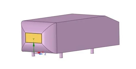
The “Ahmed” body, has the form of a highly simplified car, consisting of a blunt nose with rounded edges fixed onto a box-like middle section and a rear end that has an upper slanted surface (like a “hatch-back” car), the angle of which can be varied. The model is supported on circular-sectioned legs or stilts, rather than wheels. Despite neglecting a number of features of a real car (rotating wheels, rough underside, surface projections, etc.) the Ahmed body generates the essential features of flow around a car, namely: flow impingement and displacement around the nose, relatively uniform flow around the middle and flow separation and wake generation at the rear.
Besides the analyses of the velocity field, the Ahmed Body is also used for drag force and lift force analyses and rolling, pitching and yawing moments. The slant angle on the back allows studying the separation region and its influence on the velocity profile and forces.
The geometry of the Ahmed body is shown in the figure below. The slant angle is adjustable and is the main variable model parameters in the experimental investigations. The Ahmed body, of length (L) 1044 mm, height (H) 288 mm, and width (W) 389 mm, was placed at 50 mm from the ground (G).
Geometry :-
This is the sketch drawing:-
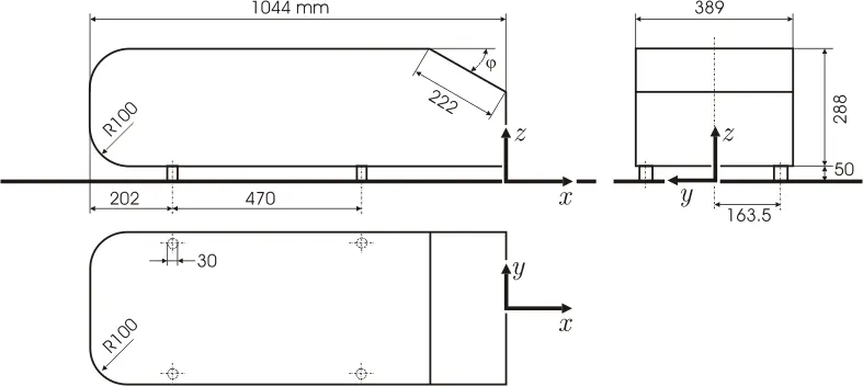
In this project, the angle of bend (φ">φφ) is 20 degrees. The geometry can be imported from another CAD software or it can be created in ANSYS. I imported a .STEP file for this project in SpaceClaim.
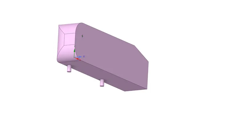
Since this is a complex simulation and the ahmed body is symmetrical along the z axis, the geometry was split into two along the z axis using ANSYS's split tool.
This is the geometry after the spliting:
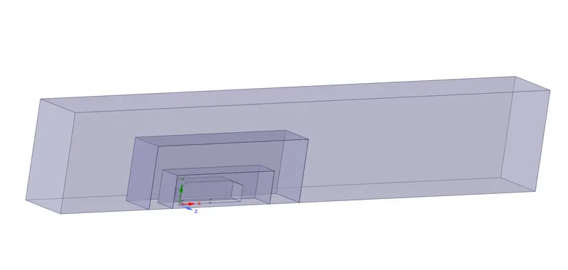
A wind tunnel has to be created around the ahmed body, there are multiple methods to achieve this, but the easiest is using the enclosure tool in ANSYS to generate the tunnel. The inlet of the wind tunnel is 2 metres from the front of the ahmed body, the outlet is 5 metres from the back of the body. The height and of the enclousure is 1 metre above the ahmed body while the width is 0.5m from the side of the body. The enclousure is checked for Interference and it is repaired as well.
Further enclousures may be created for mesh refinement.
This is the final geometry with three enclousures:
Meshing
The base size is 0.1m. There are multiple mesh controls used to generate the mesh for this geometry, they are:
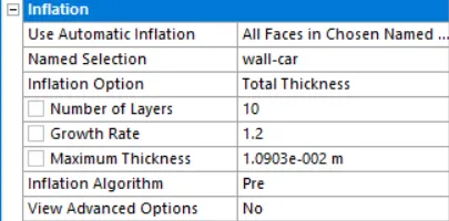
1. Mesh -> Inflation
This option is used to accurately capture the boundary layers on the surface of the body.
According to https://www.pointwise.com/yplus/index.html, for an inlet velocity of 25m/s, the wall spacing is 0.42mm. ie. The size of the element on the ahmed body should be 0.42mm high. If the initial thickness is 0.42mm, number of layers are 10 for a growth rate of 1.2 => the total thickness is 10.903mm (recall geometric progession)
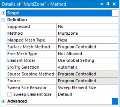
2. Method -> Multizone
This option is used to generate mesh in the outer region which is primarily hexahedral
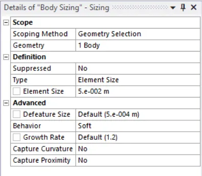
3. Sizing -> Body Sizing
This option is used to refine the larger inner enclousure of the wind tunnel. The increased size gives us more accurate results near the ahmed body. Element size is 0.05m.
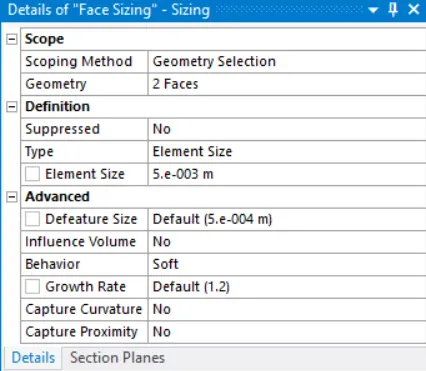
4. Sizing -> Face Sizing
This method is used to ensure that the legs of the ahmed body are circular and not polyhedral.
5. Sizing -> Body Sizing
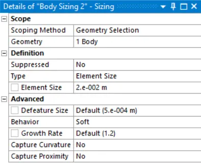
This option is used to refine the smaller inner enclousure of the wind tunnel. The increased size gives us more accurate results near the wake region. Element size is 0.02m.
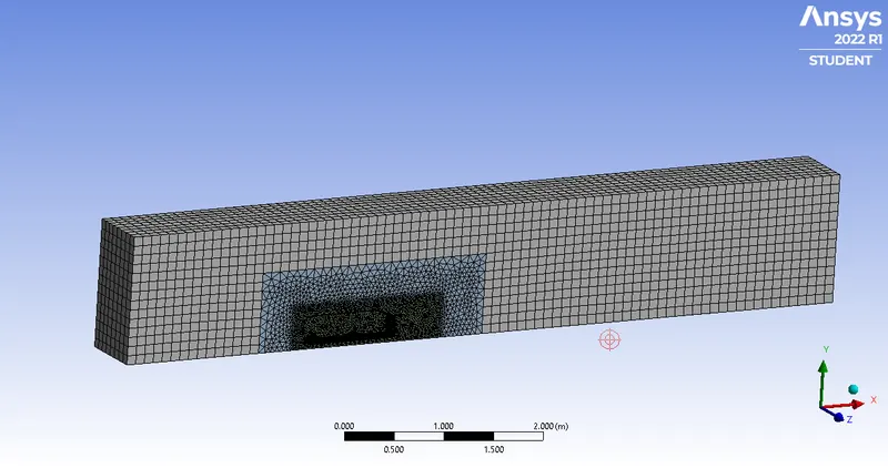
After all these controls are applied, this is the resultant base mesh:
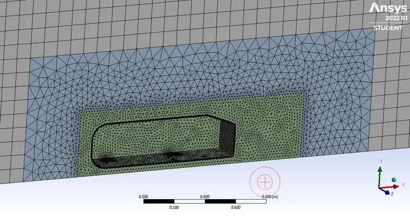
Zooming in,
These are the mesh metrics:

As seen, most elements have their quality >0.6, hence it can be said that the mesh quality is satisfactory.
Setup
Boundaries
inlet - inlet
outlet - pressure outlet
wall-car - wall (no-slip)
back, top and bottom - symmetry
symmetry zplane - symmetry
A separate boundary was created for the symmetry plane to make post processing easier.
Reference Values
The most important values here are: Area, Density, Length and Velocity.

The area was calculated using ANSYS Fluent, Results -> Reports -> Projected Areas:
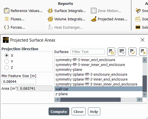
This is the cross sectional area for the half ahmed body
Materials
The existing material's (air) properties were used and were left unchanged.
We know, Reynold's Number
Re=ρ⋅u⋅Dμ">Re=ρ⋅u⋅DμRe=ρ⋅u⋅Dμ
where, ρ">ρρ is density (kg/m3">kg/m3kg/m3), u">uu is inlet freestream velocity (m/s">m/sm/s), D">DD is charesteristic length of the ahmed body (m">mm) and μ">μμ is kinematic viscosity kg/(m.s)">kg/(m.s)kg/(m.s).
In this case, μ=1.78⋅10-5kg/(m.s),D=1m,u=25m/sandρ=1.225kg/m3">μ=1.78⋅10−5kg/(m.s),D=1m,u=25m/sandρ=1.225kg/m3μ=1.78⋅10-5kg/(m.s),D=1m,u=25m/sandρ=1.225kg/m3
Re=1.225⋅25⋅11.78⋅10-5">Re=1.225⋅25⋅11.78⋅10−5Re=1.225⋅25⋅11.78⋅10-5
⇒Re=1711467">⇒Re=1711467⇒Re=1711467 or Re=1.7⋅106">Re=1.7⋅106Re=1.7⋅106
Viscous
k-omega SST was used for all simulations for this project due to its excellence in solving external flows and wake regions.
Reports
Two reports were created.
1. Lift Coefficient of wall-car
2. Drag Coefficient of wall-car
Solution - Methods
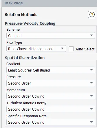
Simulation of the base setup
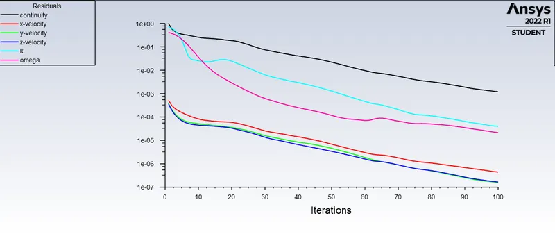
The simulation ran for 100 iterations and the results are below:
Residuals
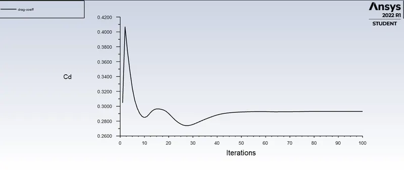
Drag Coefficient
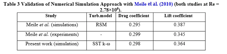
The final value of drag coefficient is 0.29310978, which is in agreement with experimental and simulation data.
This data is from Moghimi et al. [1]
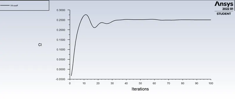
Lift Coefficient
The final value of lift coefficient is 0.24969179, the discrepancy is due to variation in reynold's number and low mesh resolution near some regions of the ahmed body.
Contours, Plots and Vectors
Note: All plots, contours and vectors were obtained from the finer mesh, due to its higher solution clarity.
1. Velocity contours
These were taken in CFD - Post.
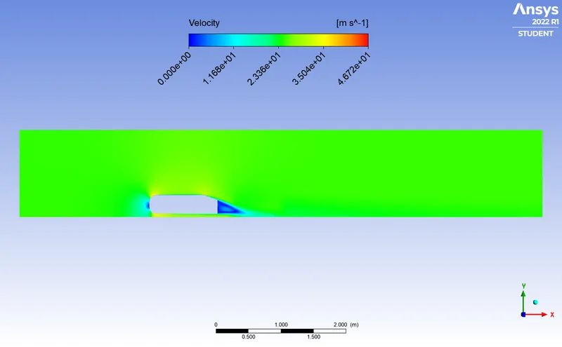
Zooming in,
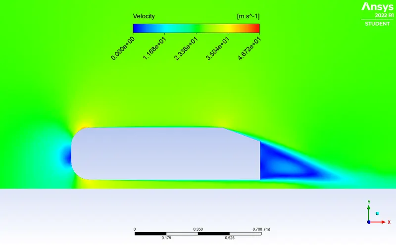
Zooming in further,
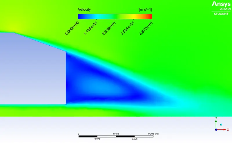
The wake is clearly visible.
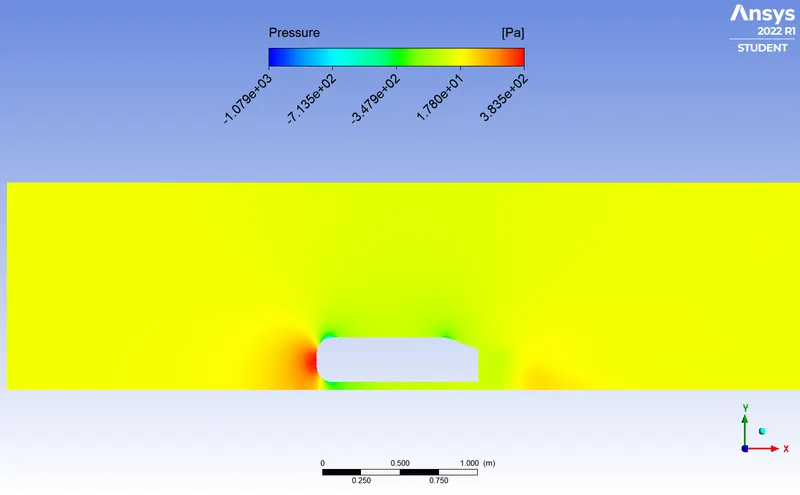
2. Pressure Contour
These were taken in CFD - Post.
Zooming in,
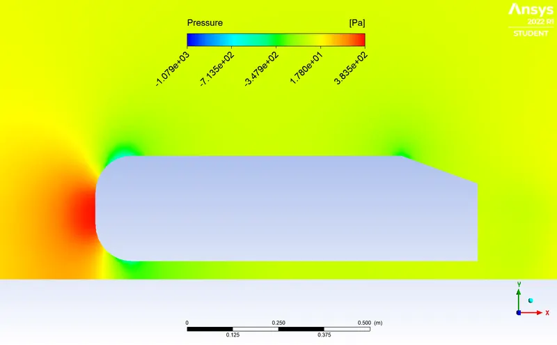
There is a high pressure region at the front of the body due to how flowing air is acculumated at the front.
The pressure is negative in some regions, this is not an error in the simulation but rather how ANSYS and Fluent functions. The "pressure" displayed in ANSYS is actually gauge pressure, the gauge pressure is 0 when the total pressure is the atmospheric pressure. In this case, the "pressure" being negative is merely the pressure dropping below atmospheric in some regions.
3. Vector Plot
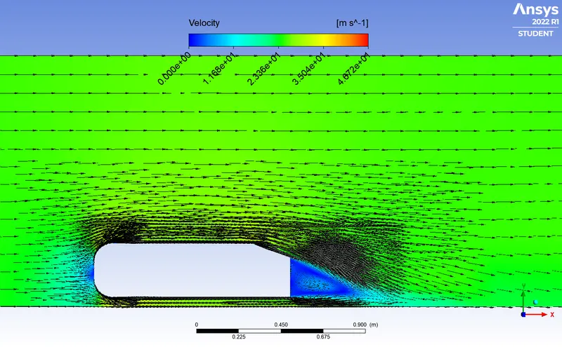
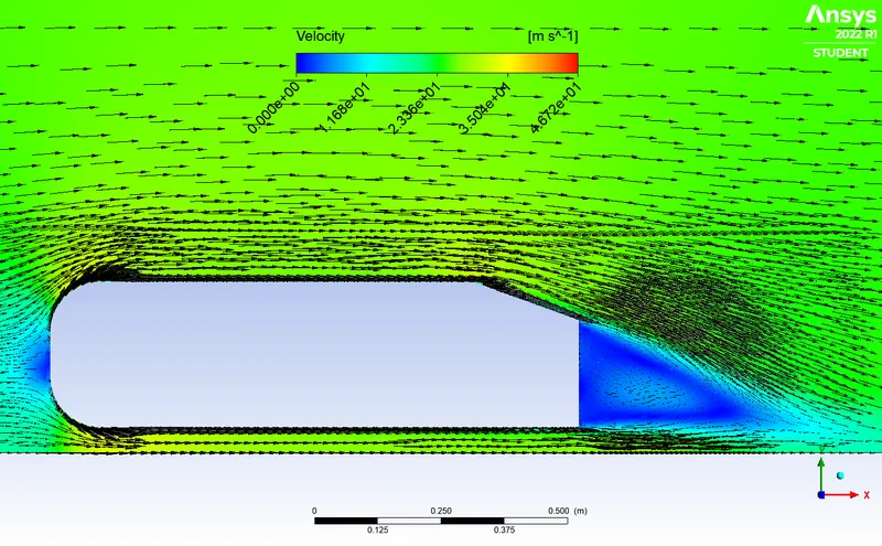
These were taken in CFD - Post. The background contour is the velocity contour.
Zooming in,
Zooming in further near the wake region,
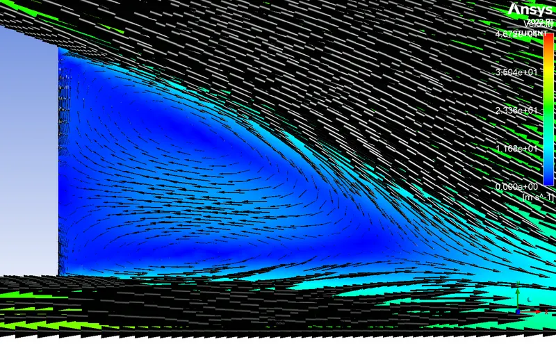
Switching the type of arrow to see the lines more clearly,
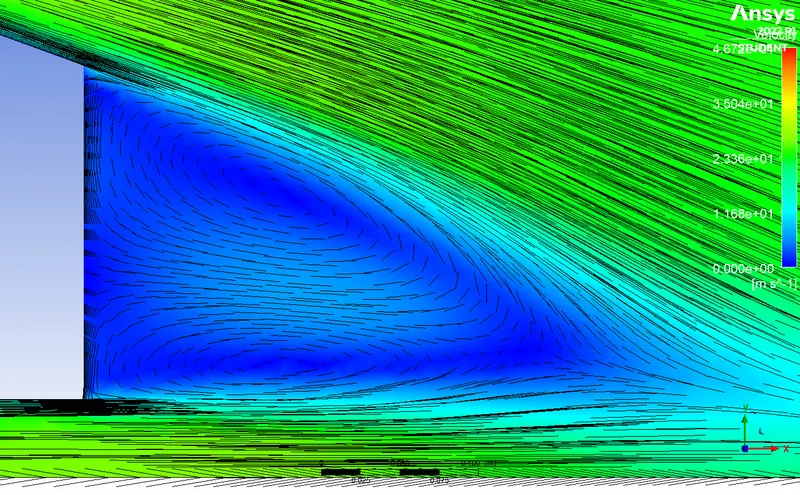
Two distinct regions can be spotted behind the ahmed body with two vortices (seen from this view) or recirculating regions behind the ahmed body.
Grid Dependence Test
A Grid Dependence Test is used to ascertain whether the final values of the solution are dependent on the mesh or not. This is an important test to ensure the simulation results are correct.
In this test, the test will involve 2 different simulations - one where the mesh becomes more finer and other where the mesh becomes more coarser.
Coarser Mesh
For this test, the smaller inner enclousure is removed (point 5 under Meshing) and the simulation is ran for the same parameters.
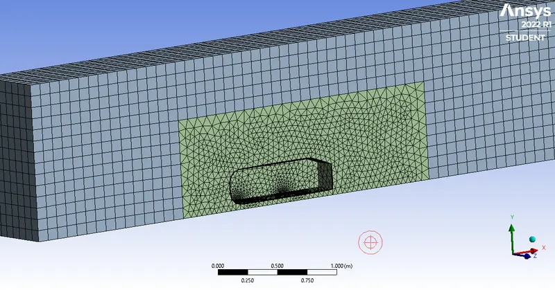
These are mesh statistics:

The values of drag and lift coefficient are below:
Lift Coefficient: 0.22592755
Drag Coefficient: 0.35537949
Finer Mesh
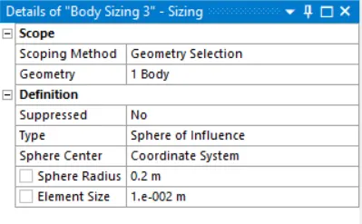
For this test, a spherical region centered at x=1.2, y=0.1 and z=0 is created and the mesh size in this region is decreased.
It was added going to Mesh -> Controls -> Sizing
This is the region seen in ANSYS:
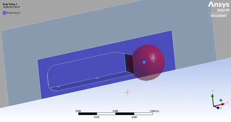
The details of the regions are below:
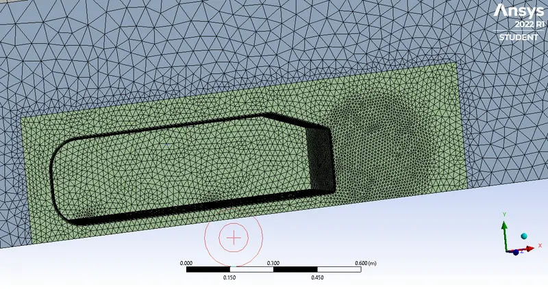
This is the resultant mesh seen in ANSYS:
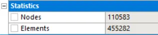
These are mesh statistics:
Other simulation parameters were kept the same as the baseline simulation and the simulation was ran:
The values of drag and lift coefficient are below:
Lift Coefficient: 0.22918563
Drag Coefficient: 0.28130557
Summary of Grid Dependence Test
| Lift Coefficient | Drag Coefficient | Nodes | Elements | |
| Coarser Mesh | 0.22592755 | 0.35537949 | 37033 | 104163 |
| Base Mesh | 0.24969179 | 0.29310978 | 83137 | 309948 |
| Finer Mesh | 0.22918563 | 0.28130557 | 110583 | 455282 |
Drag coeffcient decreases as number of elements increase, this claim is substantiated by the work of Jie Tian et al [2]
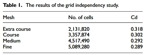
The important takeaway is that drag coeffcient does not vary significantly when the mesh is made more finer. While the drag coefficient does vary when the mesh is made more coarse. This means that the grid dependence test has passed.
Conclusion and Observations
- The simulation of the Ahmed Body runs well and is in some agreement with experimental and empirical data on the body.
- There are regions behind the body where wakes are formed, circling regions of low velocity which induce a considerable amount of velocity drag on the body. This is seen in the simulation and experimental data by Gilliéron et al.[3]
- The values of drag coefficient agree with almost all publications (Meile et al. [4]), although there is limited data for a slant angle of 20 degrees for the Ahmed Body.
- The values of lift coefficient agree with some sources and disagree with others, this discrepancy is due to coarser mesh around the botton region of the ahmed body.
- Grid Depedence Test was conducted and the test was succesful, an additional observation was also made - the drag coefficient decreases as number of elements increases. This decrease is very small and may be considered insignificant.