Week 3 - External flow simulation over an Ahmed body.
PROJECT REPORT :
AIM:
To run the simulation by considering the only half body of the perfectly symmetric body.
OBJECTIVE :
* Split the symmetric body and simulate only half of the body.
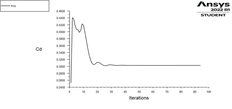
* The drag coefficient plot for a refined case.
* To perform the grid independency test and to provide the values of drag and lift with each case.
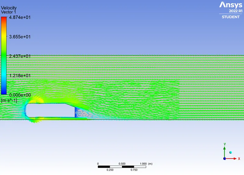
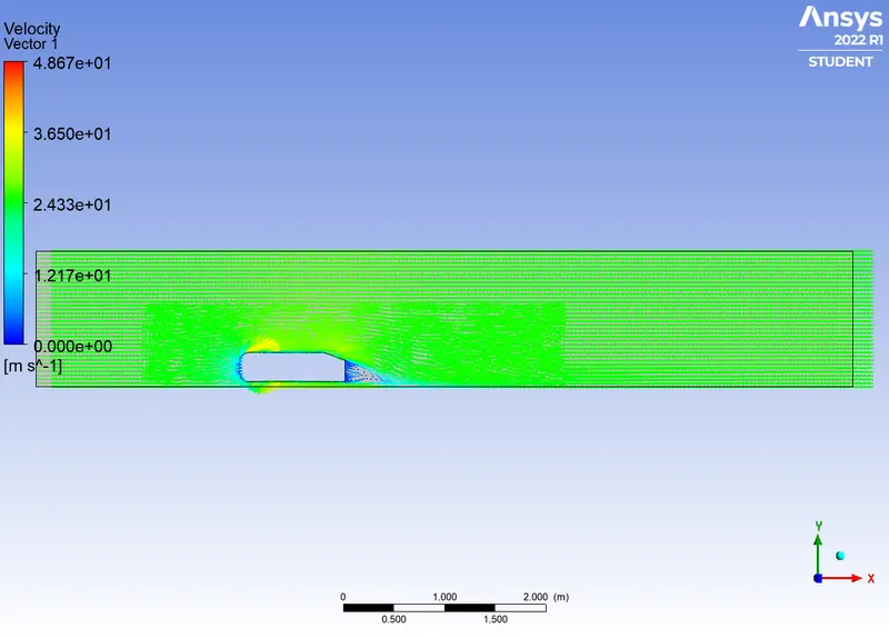
* The vector plot clearly showing the wake region.
THEOREY :
Ahmed's body :
The Ahmed Body was first created by S.R. Ahmed in his research “Some Salient Features of the Time-Averaged Ground Vehicle Wake” in 1984. Since then, it has become a benchmark for aerodynamic simulation tools.
The Ahmed body is a generic car body (a simplified vehicle model). The airflow around the Ahmed body captures the essential flow features around an automobile. This model is also used to describe the turbulent flow field around a car-like geometry. Once the numerical model in validated, it is used to design new models of the car.
NEGATIVE PRESSURE IN WAKE REGION :
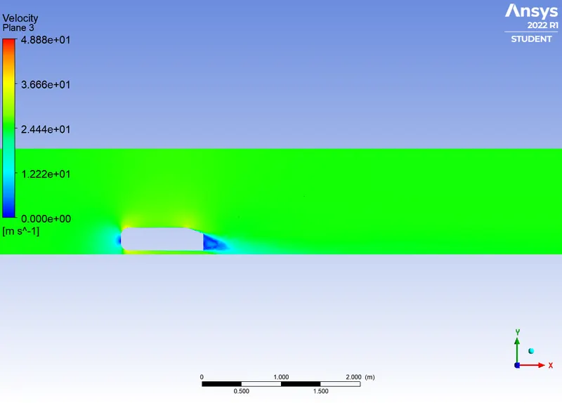
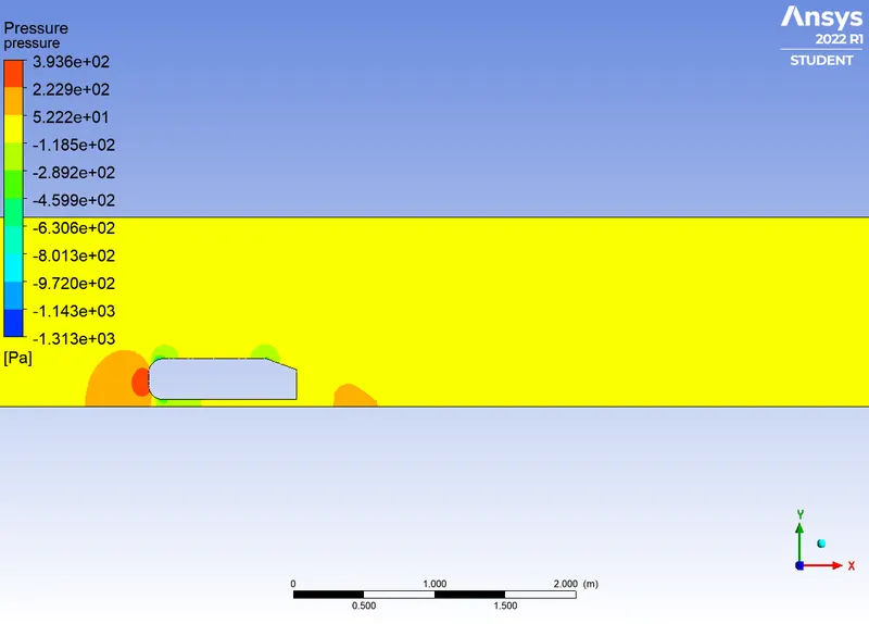
The pressure inside the wake region remains low as the flow separates and a net pressure force (pressure drag) is produced. In other words, due to the production of pressure drag being produced from flow separation, the pressure in the wake region is low. This is what is causing the vacuum.
POINT OF SEPARATION :
The fluid separation point can be defined as a point where the dv/dy i.e. gradient of velocity goes zero along with the dp/dx = 0, for the specific point. In more simplified term we can say that the point where the velocity gradient goes zero and the pressure gradient along the x- direction goes zero the point of separations starts occurring or the negative pressure gradient starts forming after that point. The point of separation cannot be understood just by single contour in hard and fast way. It can be supportively studied with the help of the dp/dx plots or velocity plots w.r.t the Y direction and other such plots in which we can see the nature of such physical properties like dp/dx=0, and dv/dy=0 experiencing in a particular region of fluid and body interaction.
PROCEDURE :
* Start by importing the given model and open the space modul to edit the model.
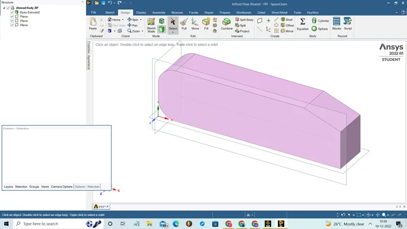
* Using the split command split the model into two half and delete one half, since the model is symmentry body and before slecting the split command we wants to create the planes as the referance axis to split the body.
* Then create a enclosure with the given geomentry and we wants to create another enclosure which is smaller than the first around the ahmed body. These is due to reduce the mesh element by creating the fine mesh on the enclosure near to body and corse mesh on the outer enclosure.
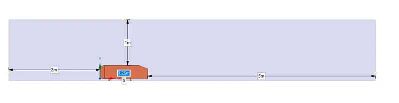
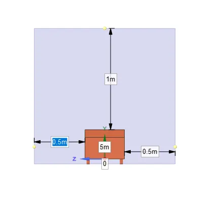
* After creating the both enclosures just wants to check the overlap of the enclosure and delete the overlap faces by using the interferance option.
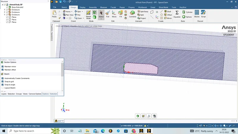
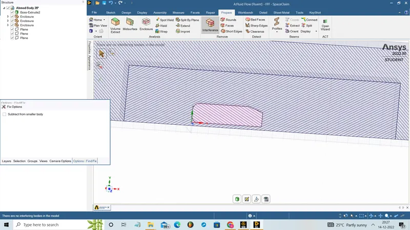
* Select the share tropology which is used to create bond between the mesh of two enclosure and so that information can easily transfer from one enclosure to other.
* After completing the geomentry open the mesh modul to mesh the model.
* Select the generate mesh option and we wants to perform the grid indepence study and so we can consider three case of element size.
* We can create fine mesh near to the ahmed body by using the sizing option with element size
* To decrease the number mesh elements create multizone by selecting the method option.
* And also create the inflamation layer near to the body to capture the effects more accurately with the different parameter for each cases. The first layer thickness and Y+ values and the number of layers should be choosen properly. The volume transition should be good and linear.
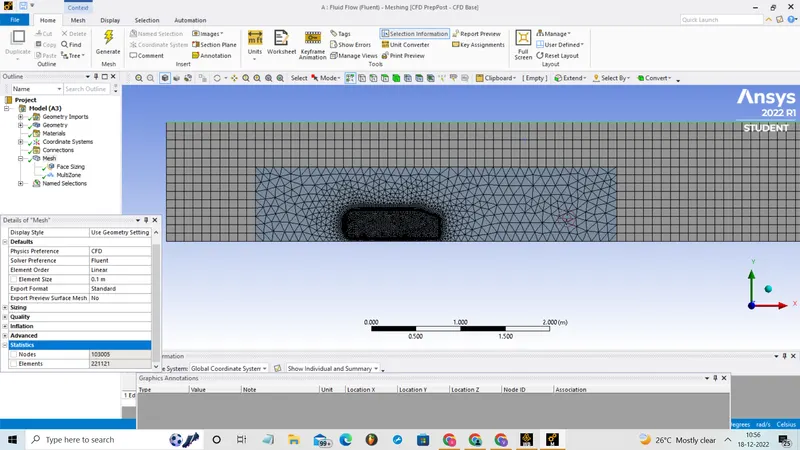
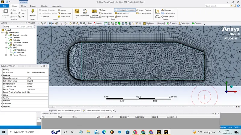
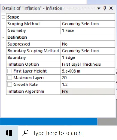
* After the mesh open the set up modul and here we have to set the condition like physics, boundery conditions, type of analysics, Solution setups and the requried outups.
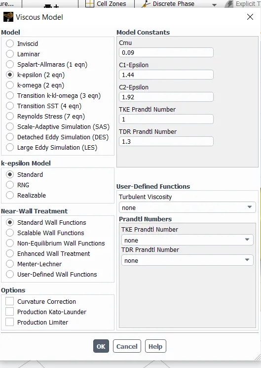
* In these we use the pressure based steady state simulation and Select the realizable lamina model by opening the physics menu and select viscous model.
* Select air as working fluid by clicking the material option and don't change the default density and viscosity.
* Then we have to set the boundary conditions by the option boundries . select the inlet and set as 25 m/s.
* Then solution set up as to be made to get the coefficient lift report and the coefficient of drag by selecting the definition in the solution and select the new and go to force report.
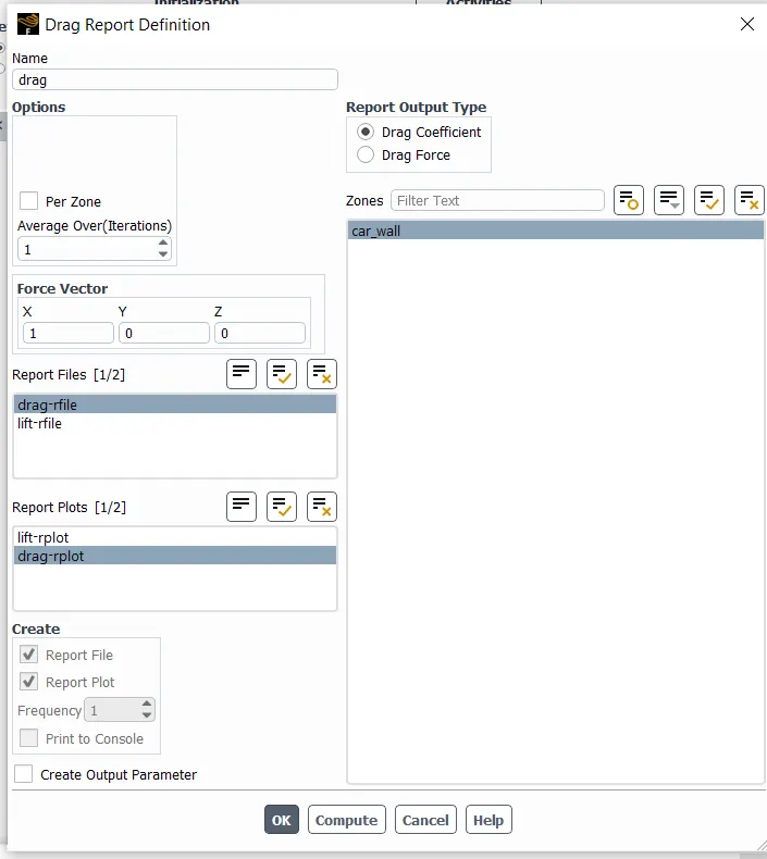
* Set the referance value.
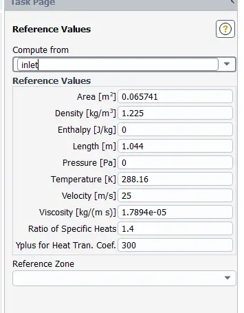
* Select the method as the simple method and initialize it.
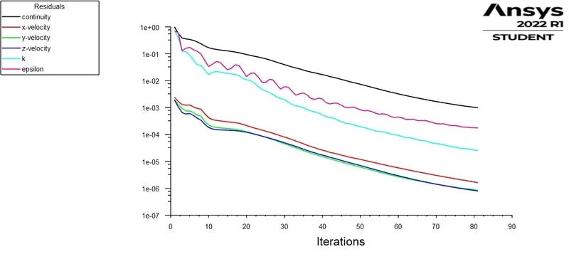
* Give 300 iteration and if the solution is not converged and then increase the iteration and calculate it.
* Create the contours for pressure and velocity in the created plane.
* In the result option we can create the plots for pressure and velocity which is used to compare both the case.
* For the case 2,3 we can dubilicate the case 1 and just change the element size as per the number of elements in the setup option.
RESULT :
CASE-1
Simulation of flow for the steady condition for element size=100mm.
RESIDUAL PLOT:
COEFFIENT OF LIFT :
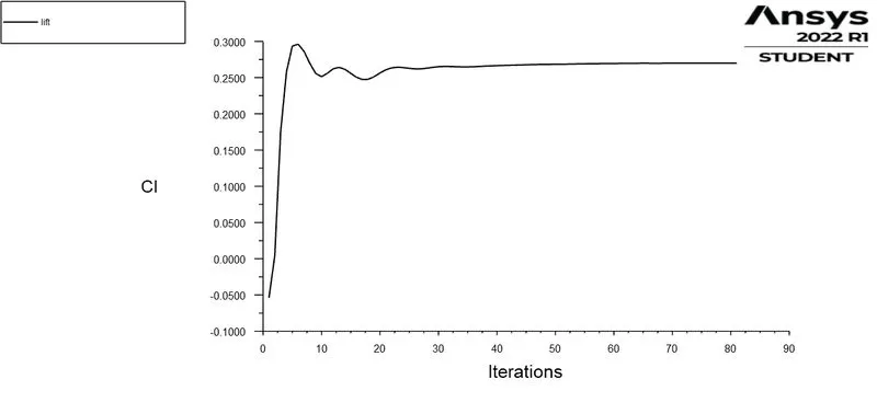
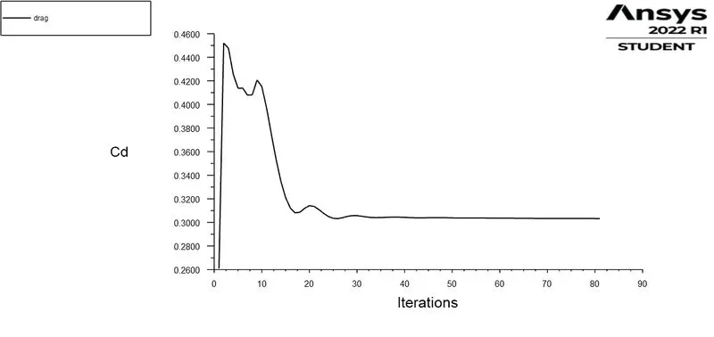
COEFFIENT OF LIFT :
VELOCITY CONTOUR :
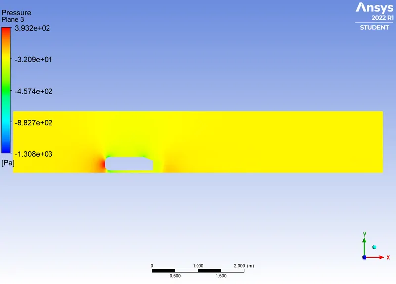
PRESSURE CONTOUR :
VELOCITY VECTORS :
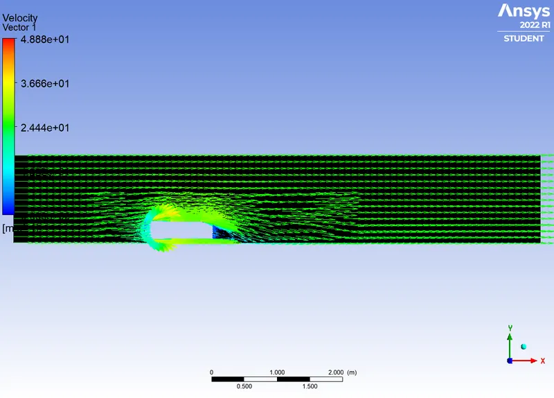
CASE-2
Simulation of flow for the steady condition for element size=50mm.
RESIDUAL PLOT:
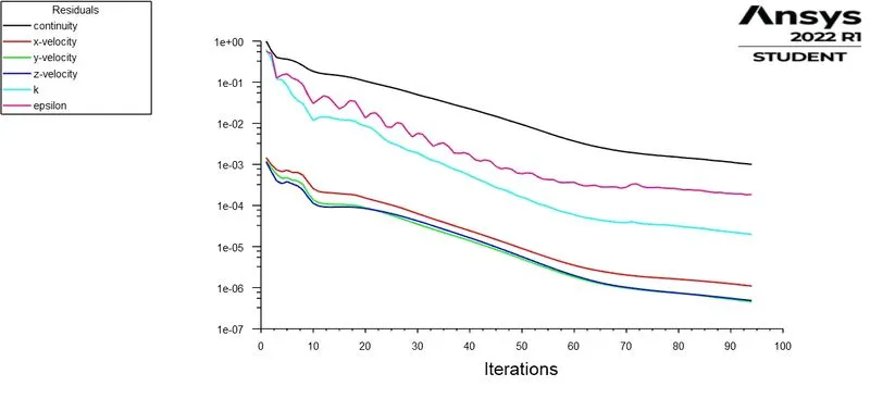
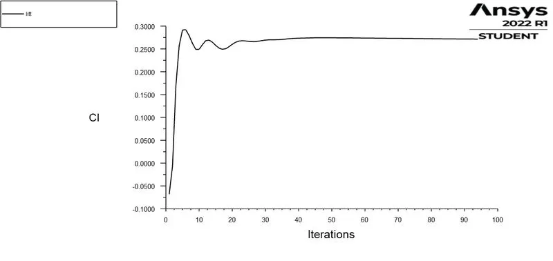
COEFFIENT OF LIFT :
COEFFIENT OF DRAG :
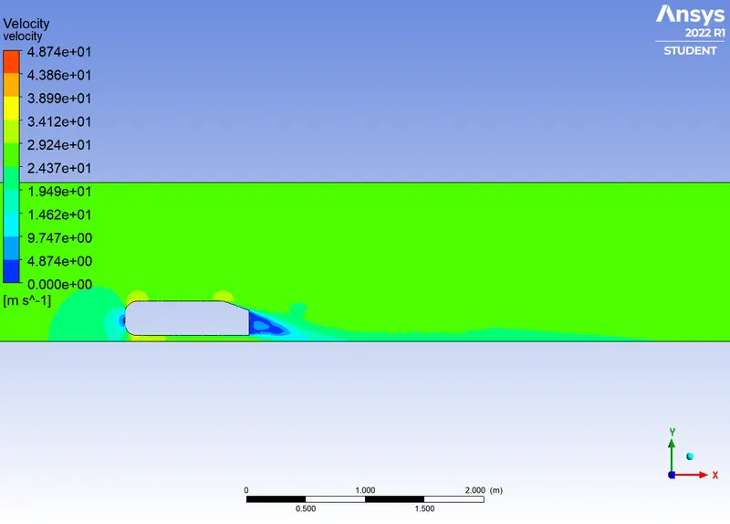
VELOCITY CONTOUR :
PRESSURE CONTOUR :
VELOCITY VECTORS :
CASE-3
Simulation of flow for the steady condition for element size=38mm.
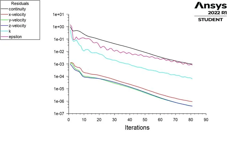
RESIDUAL PLOT:
COEFFIENT OF LIFT :
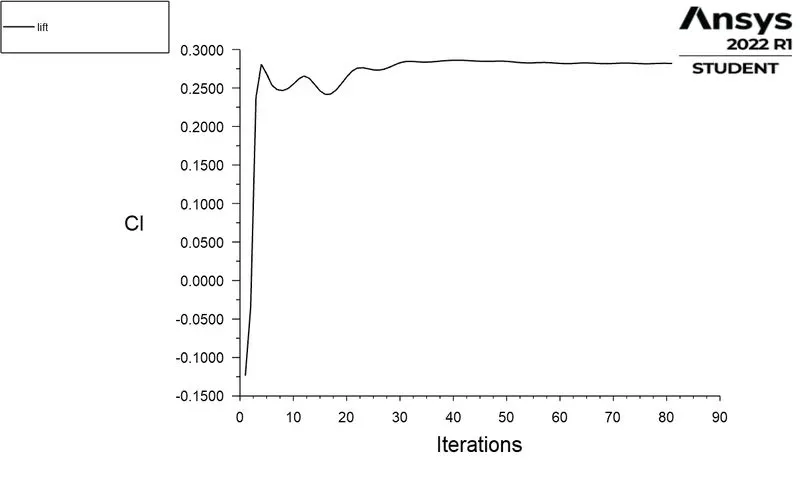
COEFFIENT OF DRAG :
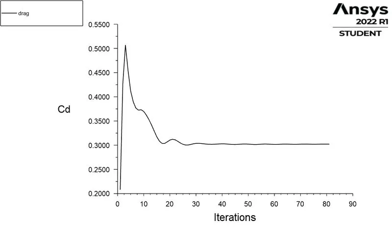
VELOCITY CONTOUR :
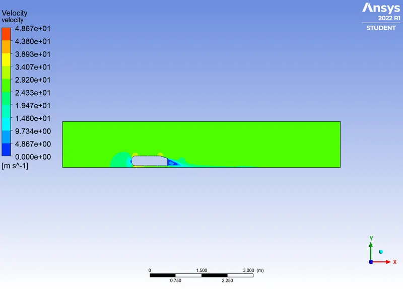
PRESSURE CONTOUR :
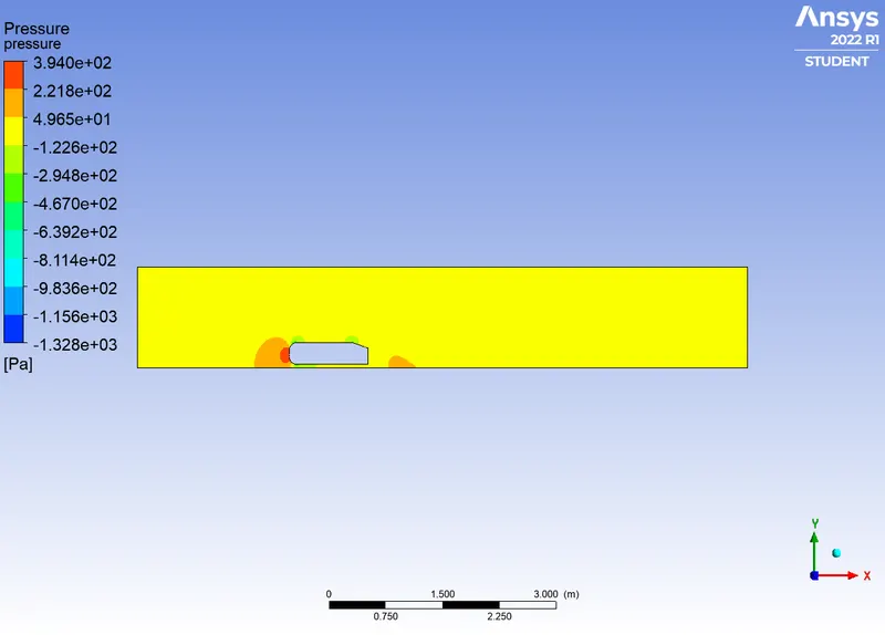
VELOCITY VECTORS :
Grid independence test
| number of cells | C_d | C_L | |
| case 1 | 221121 |
0.30331375 |
0.26992105 |
| case 2 | 318192 | 0.30231568 |
0.27155412 |
| case 3 | 450387 |
0.30216964 |
0.28182953 |
Conclusion:
- High pressure is formed at the frontal area of the Ahmed body due to the loss of kinetic energy of the air.
- The adverse pressure gradient is created near the wake regions because of the flow separation which is occurring because of the geometry of the model. As a result flow separation alters the pressure gradient which in turn affects the drag and lift coefficients.
- In order to reduce the size of the wake region, detachment of the fluid should be farther away from the body which can be achieved by an increase in the slant angle.
- With the increase in mesh size, the numerical results approach closer to experimental results.