Week 3 - External flow simulation over an Ahmed body.
Objective:
Run the simulation for the velocity of 25 m/sec with the default air properties in fluent.
For this challenge, you will have to provide answers to the following questions:
Q1. Describe Ahmed's body and its importance.
Q2. Explain the reason for the negative pressure in the wake region.
Q3. Explain the significance of the point of separation.
Expected Results:
- Velocity and pressure contours.
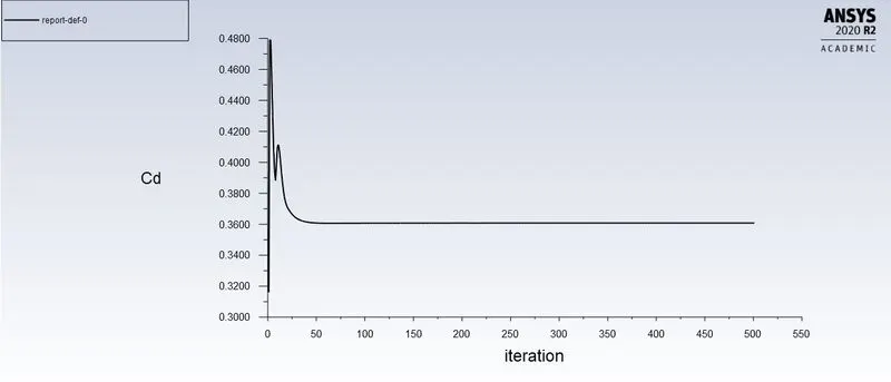
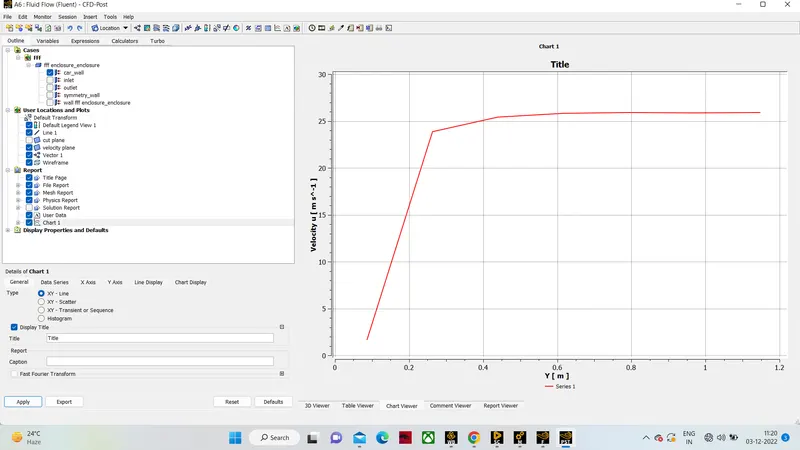
- The drag coefficient plot for a refined case. (For velocity of 25m/sec, the drag coefficient should be around 0.33).
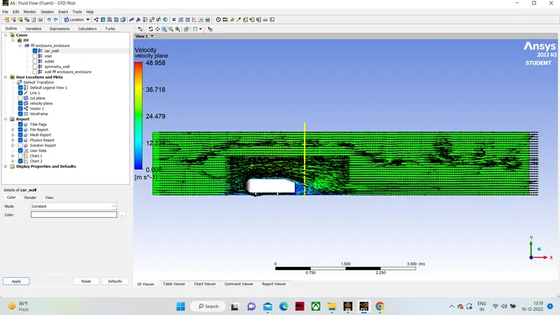
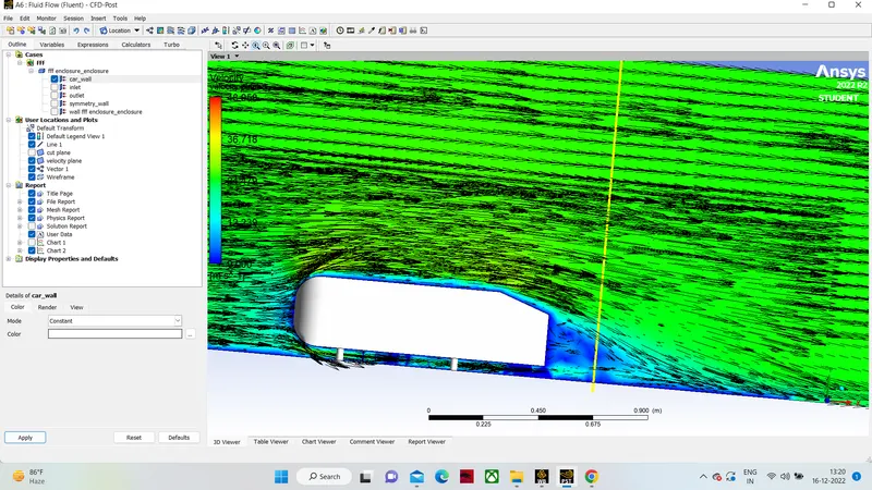
- The vector plot clearly showing the wake region.
- Perform the grid independency test and provide the values of drag and lift with each case.
Q1. Describe Ahmed's body and its importance.
The Ahmed body is simplified car body used in automotive field to study the impact of the flow pattern on the drag. The external aerodynamics of the car defines many major traits of an automobile like stability, comfort and fuel consumption at high speeds. The flow around the vehicle is characterized by high turbulent and three dimensional flow separations as well as there is a growing need for more insight into the physical features of these dynamical flows. The Ahmed Body is a simplified car, used in automotive field to investigate the flow analysis and find the wake flow around the body. Ahmed body is made up of round front part, a moveable z slant plane in the rear of the body to study the detachment phenomena at different angles, and a rectangular box which link the front part and the rear slant plane. The principal objective to study such a simplified car body is to tackle the flow processes involved in drag production. Through perceiving the mechanisms involved in creating drag one can be able to design a car to minimize drag and therefore reducing fuel consumption and maximize vehicle performance.
Important of Ahmed body:
An Ahmed body represents a simplified like vehicle volume which helps understand the fundamental physics defining by the engineers the lift and drag forces and coefficients at certain characteristically velocities, pressure differences, and seeing and analyzing the vortices, turbulence and Reynolds number obtained. ANSYS is a general purpose FEA and CFD simulation software. It gives numerical prediction of the behavior of a system.
These numerical predictions need to be validated by experimental data. People working in vehicle aerodynamics use Ahmed body to validate their numerical model because the experimental data from wind tunnel testing is available for Ahmed body. Once the numerical model in validated, it is used to design new models of the car.
Its shape is simple enough to allow for accurate flow simulation but retains some important practical features relevant to automobile bodies. This model describes how to calculate the turbulent flow field around a simple car-like geometry using the Turbulent Flow, k-epsilon and k-omega interface. Later, either experimentally or computationally it can be recreated all the same but with a desired geometry, new to come up to the market or a research.
The Ahmed body was described originally by S. R. Ahmed in 1984 [1]. Three main features were seen in the wake:
- The A recirculation region that is formed as the flow separates at the top of the vertical back surface of the model
- The B recirculation region that is formed due to the separation at the base of the model.
- The c-pillar vortices that form as the vorticity in the side boundary layers roll up over the slant edges.
The wake was shown to be highly dependent on slant angle. For slant angles less than 12°, the flow remains attached over the slant. The flow is essentially two-dimensional and has low drag. Between 12° and 30° the flow becomes much more three-dimensional as the c-pillar vortices form. These reach maximum strength at 30°. The drag increases significantly as the low-pressure cores act on the rear surfaces. Past 30° the flow separates fully off the slant. This results in a sudden decrease in drag and weaker c-pillar vortices.
Q2. Explain the reason for the negative pressure in the wake region.
The negative pressure is due to the velocity difference applied at a certain Reynold number and the rear angle, which at a low Reynolds number when this difference in pressure happens the wake obtained increases the drag due to the pressure drop behind the Ahmed body, which at a high Reynolds number due to the vortices generated it produces small amounts of pressure thrusting the body.

Q3. Explain the significance of the point of separation.
The point of separation defined by the Ahmed body and the flow, the alpha angle depending on which value is at it causes change in flow direction, forces required, lift on the body, induced drag due to “tip vortex”, at a critical value flow in slant stalls and reduced lift-reducing as well drag, all depending on the value of alfa and the Reynolds number.
Geometry:
The geometry description is as shown below.
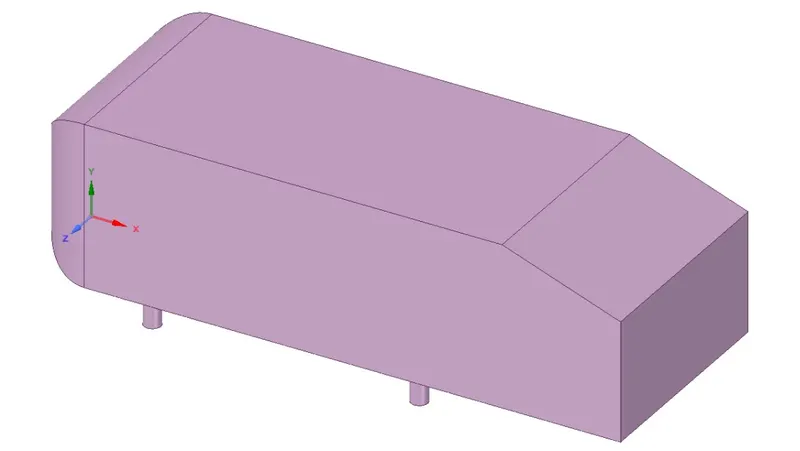
Ahmed body 3D geometry
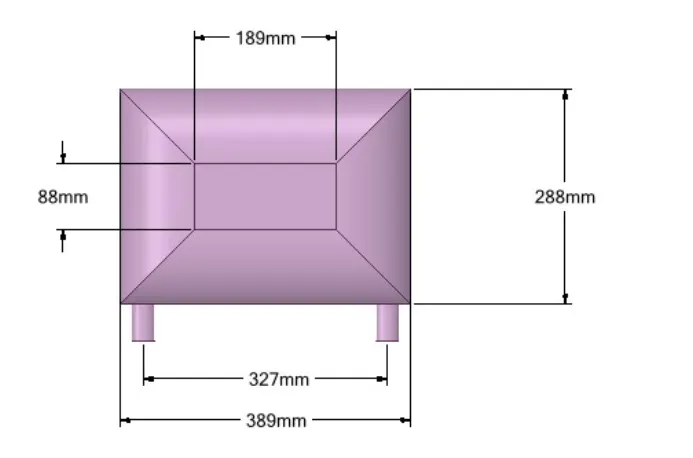
Ahmed body front view
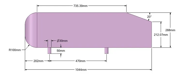
Ahmed body side view
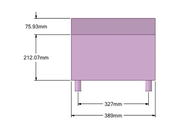
Ahmed body rear view
Generating simulation for baseline mesh:
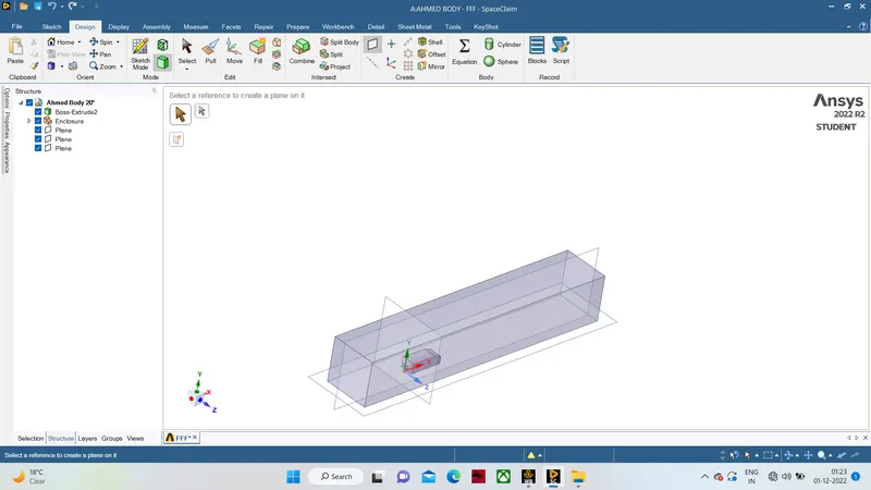
- Right face is located at a distance of 5m from the right side face of Ahmed body along the X axis.
- Left face is located at a distance of 2m from the left side face of Ahmed body along the X axis.
- Top face of the encloser is at a distance of 1 m from the top side face of the Ahmed body along the Y axis.
- The bottom face of the encloser is attached to the bottom face of the Ahmed body along the YZ plane.
- The front and back face of the encloser is at a distance of 0.5 m along the Z axis.
- The geometry is suppress for physics.
Meshing- mesh the enclouser with default element size .with the proper name selection Inlet,Outlet,Car wall and Symmetry wall.
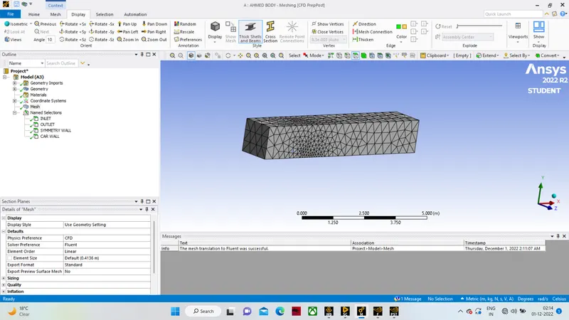
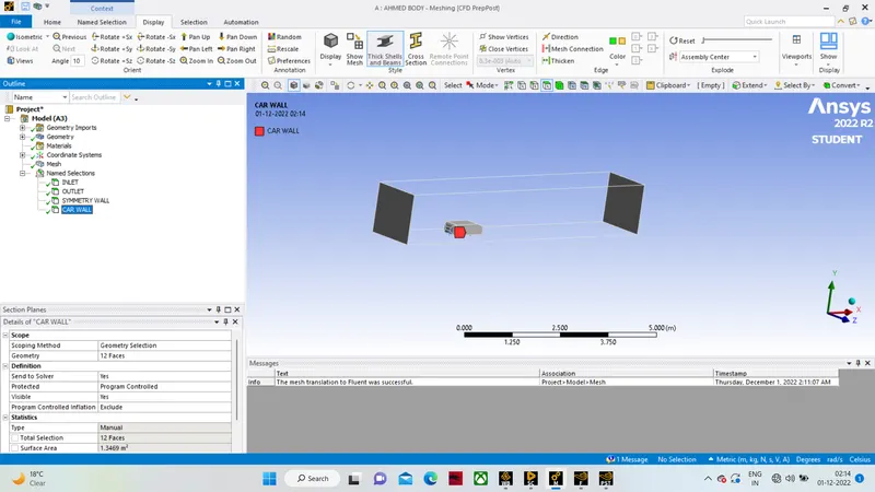
Setup physics and results-
- density based solver
- energy equations turned on .
- e epsillon turbulence model.
- air as material with default prpoperties.
- inlet velocity is 25 m/s
and pressure otlet at zero gauge pressure.
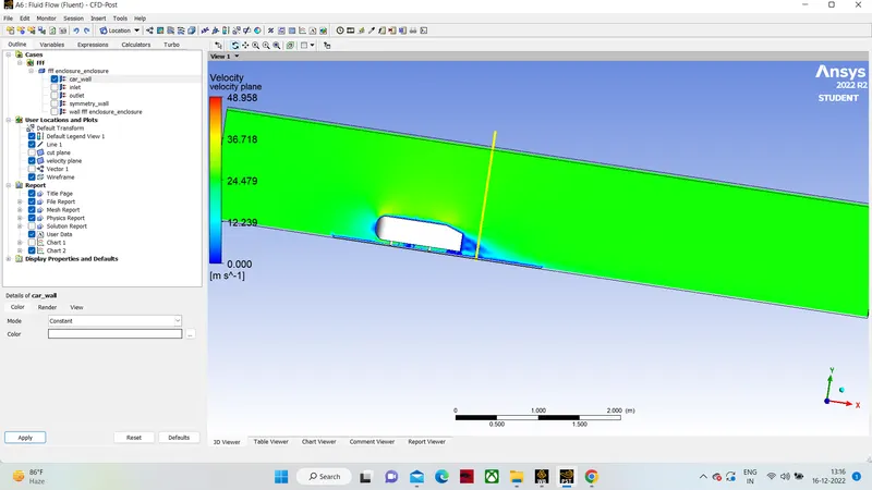
Contour- velocity contours at baseline mesh.
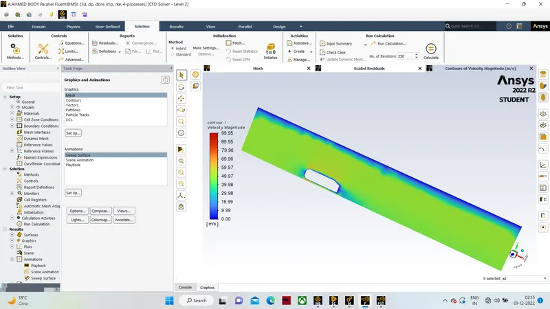
Vector plot-
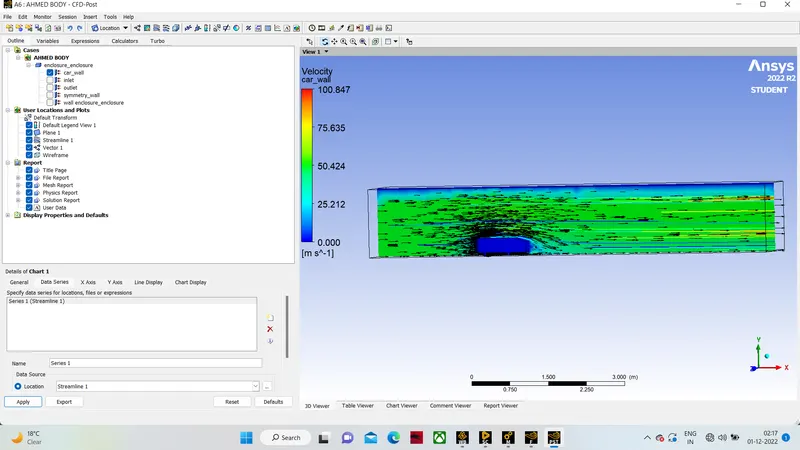
through base line mesh simulation we got that result there is a critical region just after the ahmed body .we should refine the mesh in that area to get a meaningfull result.
Refinine mesh-
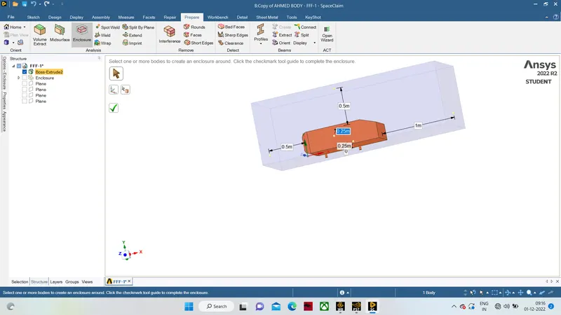
as we know the critical area is just after ahmed body then we create another enclosure with 0.50 meter from front and 1meter from rear area of ahmed body.
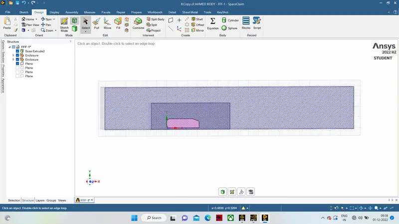
as we can see in the picture there is a huge interference .Initially there was a huge interference between the Outer and Inner encloser so that the mesh gets overlapped which gets not acceptable so to avoid this we made share topology and get deleted the Interference region that by using the interference command after this we get a good interaction between the Inner and Outer enclosers so that we can get the mesh properly.
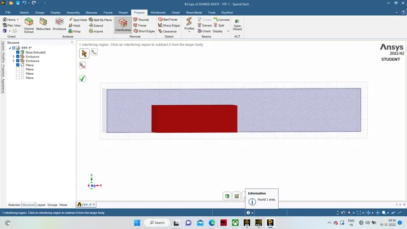
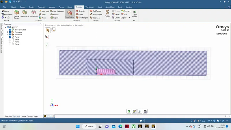
Also shared topology for conformal meshing.
Boundary Conditions:
Standard k-epsilon model with Inlet Velocity, V=25m/s, Density of air = 1.225 kg/m3, temperature = 300k and viscosity = 1.7894e-5 kg-s/m.
Boundary conditions are - uniform velocity at inlet, uniform pressure at outlet , symmetry at wall.
Meshing:
The Ahmed body is surrounded by a very fine hexahedral grid to record flow structures and inner enclosure is surrounded by tetrahedral grid. To accurately capture the flow separation from its rear.
CASE 1:
where, 1st box domain = 100mm size of hexahedral mesh
2nd box domain = 50mm size of tetra mesh
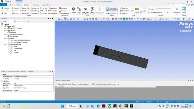
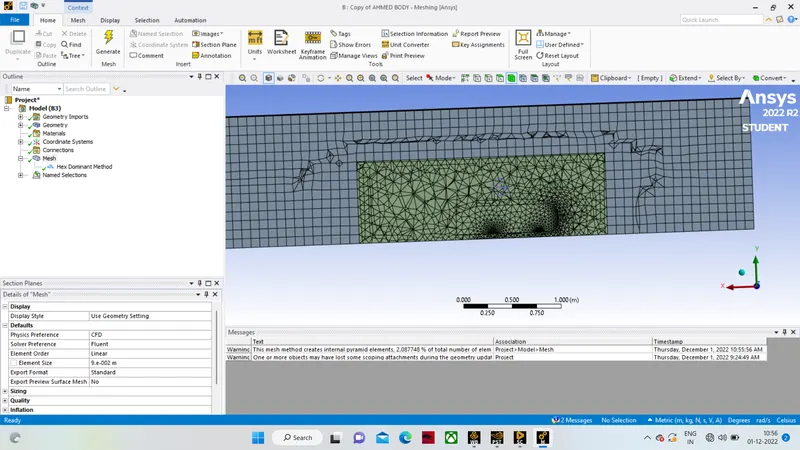
actually we can more refine the mesh and also add inflation layers for more accuracy but due to limitations of my machine i am not adding layers and more refine mesh.
Setup physics and solver-
the physics setup will be same for this also .
- density based solver
- energy equations turned on .
- e epsillon turbulence model.
- air as material with default prpoperties.
- inlet velocity is 25 m/s
and pressure otlet at zero gauge pressure.
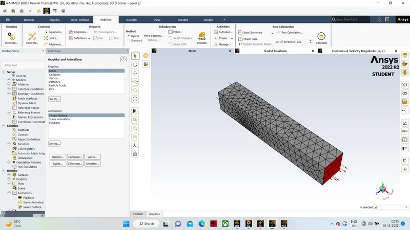
Drag-coefficient plot:
Velocity contour plot:
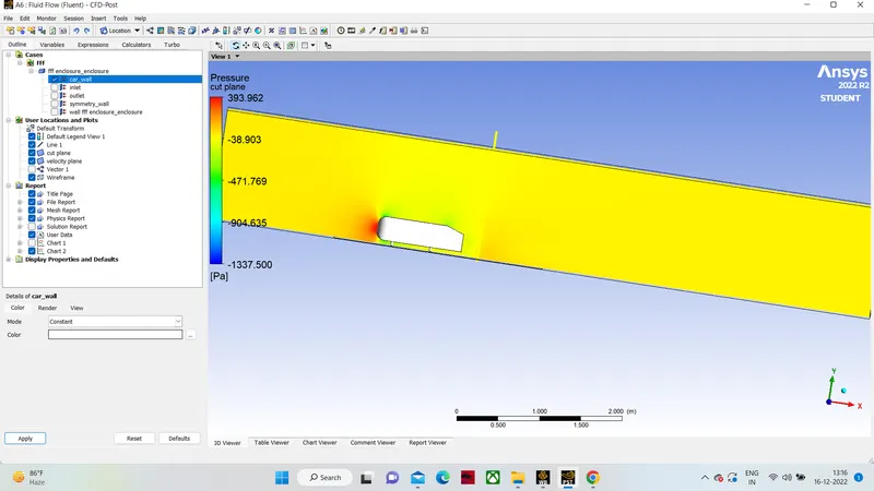
Pressure contour plot:
Velocity vector plot:
Result and Conclusion:
The baseline mesh gave a poor result, it wasn't able to capture the flow around the Ahmed body and the wake structure, due to coarse mesh.
The refined mesh gave better results. The plots show the wake formation accurately and the flow around the Ahmed body was also captured pretty well.
There is a variation of pressure across the Ahmed body. The pressure in front of the body is positive because that's the location where the flow first comes in contact with the body and comes to rest. At the corner, the flow accelerates, thereby decreasing the pressure.
The reason behind negative pressure in the wake region is due to flow separation, recirculating flow. It's a phenomenon that generally happens as the air moving past the body isn't able to pass through the immediate backside of the body creating a region, where there is no movement of air and thereby creating a pressure gradient.
As the wake flow is the main contributor to the drag force(pressure drag), the point of separation is an important aspect of the flow. The more attached the flow is to the body the recirculation zone will be smaller and hence reduce the adverse effect of pressure drag, improving the fuel efficiency of the body.