Week 3 - External flow simulation over an Ahmed body.
Aim : To simulate the flow over Ahmed body and to plot for velocity and pressure contours, the vector and drag coefficient plot.
theory-
ahmed body-
The Ahmed body is a geometric shape first proposed by Ahmed and Ramm in 1984. The shape provides a model to study geometric effects on the wakes of ground vehicles
Lift-
Lift is the perpendicular force executed by the fluid ( Eg : air ) on the body.
Lift is generated by the combination of Bernoulli’s principle and Newton’s third law.
Drag-Drag force is the resisting force caused by motion of a body through a fluid.
wake region-When the air moving over the vehicle is separated at the rear end, it leaves a large low pressure turbulent region behind the vehicle known as the wake. This wake contributes to the formation of pressure drag, which is eventually reduces the vehicle performance.
Point of Seperation :
Separation of flow is said to occur when the direction of the flow velocity near the surface is opposed to the direction of the free stream velocity, which means `(du)/(dy)<=0`. Here the skin friction coefficeient reaches to a vlue of zero. At this point the wall shear stress vanishes and is called the point of seperation. Reverse flow take place beyond this point. due to reverse flow large eddies are formed and a lot of energy is dissipated. this region is inturn called as wake.
procedure-
1) import the body to space claim
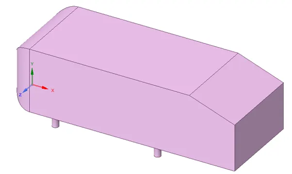
2)now we need to prepare an enclosure for fluid simulation we can do this by enclosure option in prepare panel
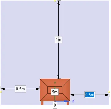
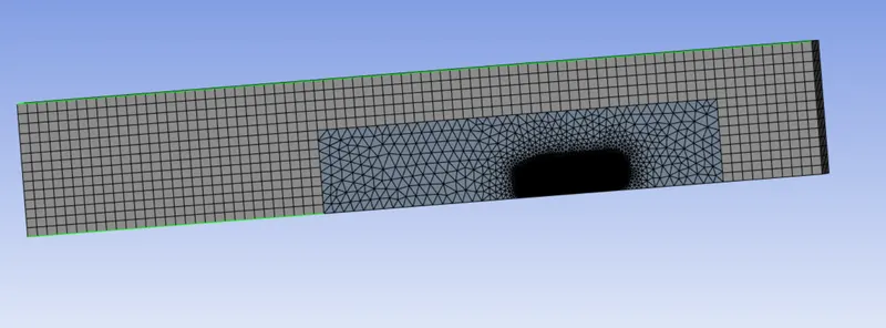
3) after preparing the enclosure we need another smaller enclosure to create a fine mesh that will give us more accurate results in the are aof intrest i.e that is above the vehicle body this will ensure our element count stays minimum while still getting accurate results we can create another enclosure using same method as above and than click on interference option so both enclosure share mesh in that area
4) as we know that the model is symmetrical we can split the midelm in two and we can supress the ahmed body and half of the enclosure for physics
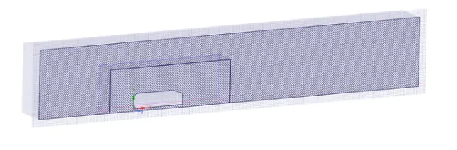
5) we can name faces using face select as inlet outlet and ahmed body
MESHING-
1)no we go to the meshing deck Open meshing interface and r click on to mesh to insert method
2)first insert a meshing method i used multizone to generate mesh as it tries ti give hexa mesh where possible
3) now we can insert sizing select the faces of ahmed body region enter the sizing
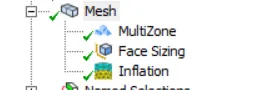
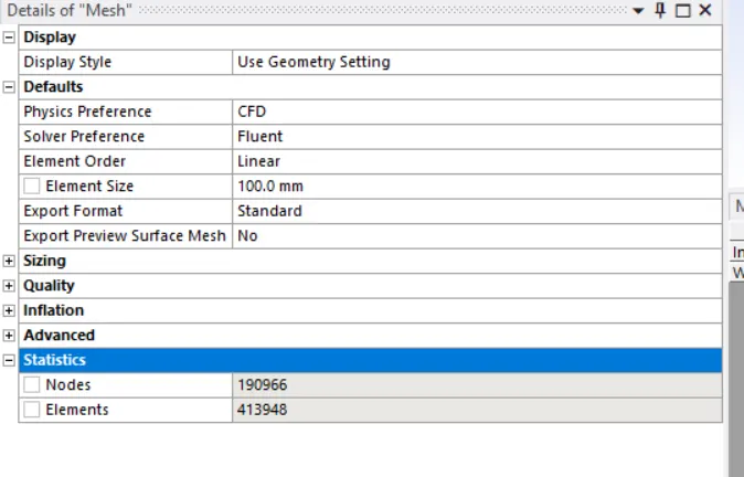
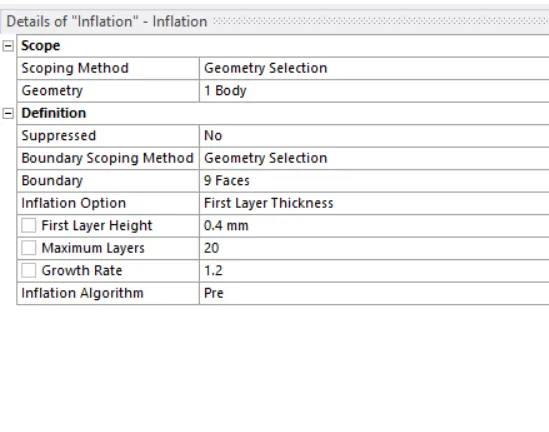
4) now add inflation layer method and using online y+ calculator we can get first layer thickness whic came to be 0.4 mm
5)now click on generate mesh
Setup-
1)now we can go to setup since mach no. is less than .3 we will go with pressure based solver
2)we will choose viscous k epsiolon model as our y+ value is more than 3
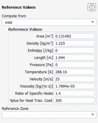
3) set the boundary cond inlet vel to 25m/s
4)add material as air
5)Set Reference values
6) create a report for lift and drag
7)create a plane for vel and pressure plot
repeat the same for each cases
| case | No. of elements(million) | meshing method | first layer thickness | lift | drag | element size |
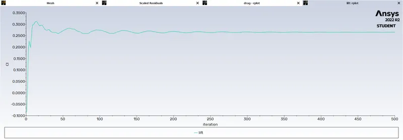
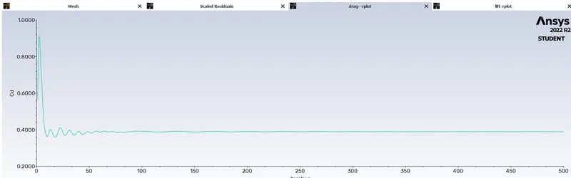
| 2 | 0.49 | auto | auto smooth method | 0.27 | 0.38 | 10 |
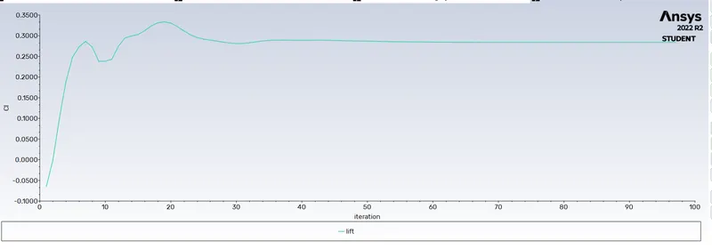
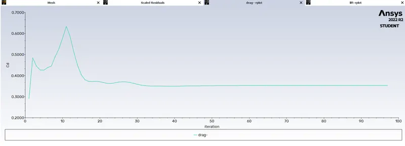
| 1 | 0.4 | multizone | 0.4 | 0.28 | 0.35 | 10 |
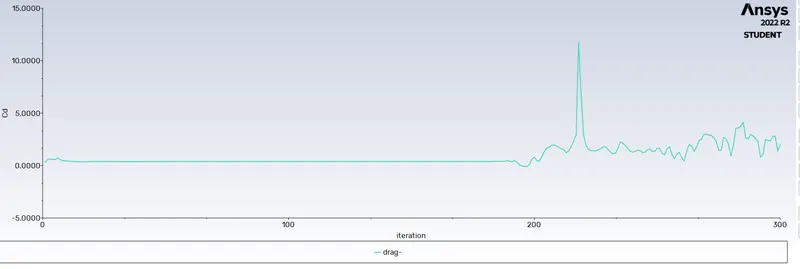
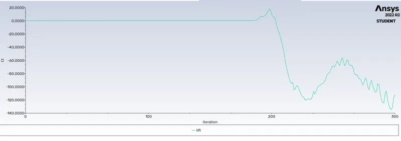
| 3 | 0.11 | multizone | 0.4 | -101 | 1.8 | 100 |
Results Case 1-
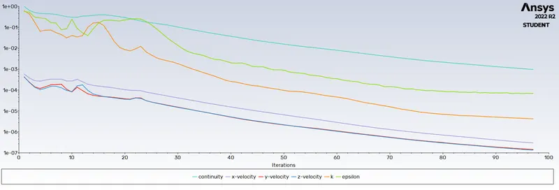
residue plot-
Lift plot-
Drag plot-
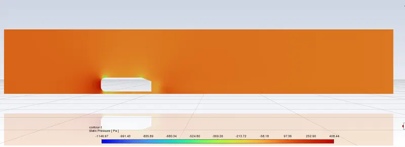
Pressure plot-
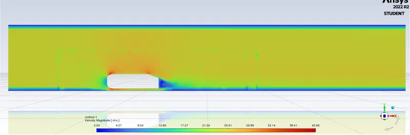
Velocity plot
Results case 2-
Lift plot
Drag plot-
velocity plot-
Pressure plot-
Results case 3-
Drag plot-
lift plot-
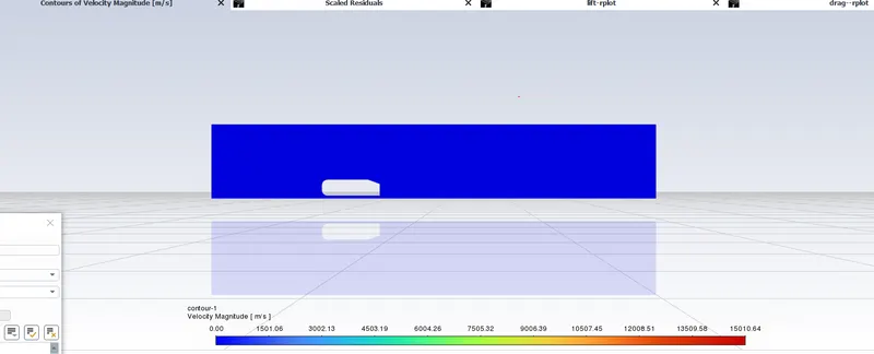
vel and pressure plot-
Conclusion-
1)as we can see from the plots case 1and case to are able to capture wakeregion, vel plot verry accurately due o lower element size
2)the change in method of inflation layer from soft to first layer thickness brought some slight change in values of drag and lift
3) We observed that a wake region(a large recirculation region) have established at the rear side of Ahmed body in velocity flow Which have created a vortex flow at rear side