Week 3 - External flow simulation over an Ahmed body.
aim
studying External flow simulation over an Ahmed body.
Theory
Ahmed body:
Ahmed body is a generic car body (a simplified car model) i.e the flow of air around the Ahmed body captures the essential flow features around an automobile. The aim of the benchmark validation was to evaluate the TCFD, computational fluid dynamics (CFD) software, and compare its results with the measurement data.
The flow for the model is turbulent which is based on velocity and body length. For the default mesh size in ANSYS-FLUENT we will use K-epsilon model and for the later stage k-omega SST model is used.
use of Ahmed body
The Ahmed body is a benchmark model widely used in the automotive industry for validating simulation tools. The Ahmed body shape is simple enough to model, while maintaining car-like geometry features.
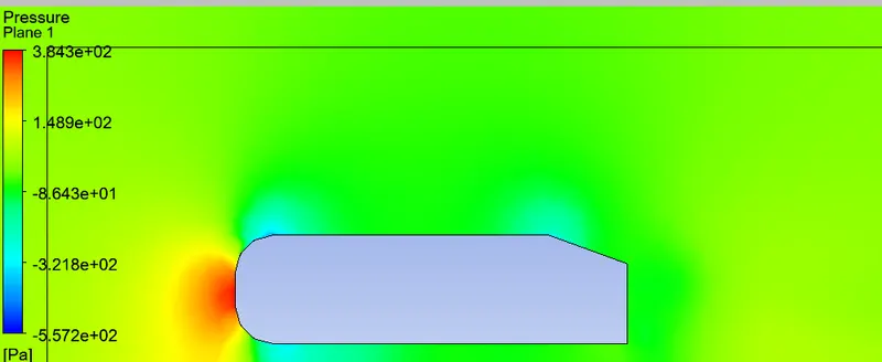
Negative pressure in the wake region
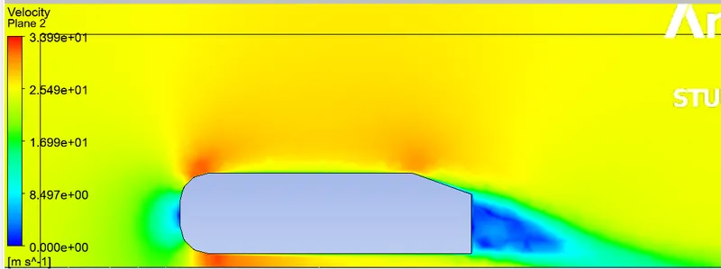
When the air moving over the vehicle is separated at the rear end, it leaves a large low-pressure turbulent region behind the vehicle which is known as the wake. This contributes to the formation of pressure drag which affects the vehicle performance.
When the vehicle is moving at a certain velocity the fluid imparts viscous force to the vehicle as long as it is in the viscous sublayer of the boundary. When the fluid reaches the rear end of the vehicle it gets detached from the surface of the body causing negative pressure in the wake region. The movement of the fluid around the vehicles depends on the geometry of the car and the Reynolds number.
Solving & Modelling approach
As the body is perfectly symmetric, we can run the simulation by considering the only half body. This is the best practice where you can save on the number of cells and get the results faster as well.
The geometry which is provided with the challenge needs a modification which you should be able to do at this stage of a course. You need to use the 'split body' command in SpaceClaim to perform the operation and then you can use the symmetry boundary condition in fluent to perform the simulation.
Run the simulation for the velocity of 25 m/sec with the default air properties in fluent.
Expected Results:
1. Velocity and pressure contours.
2. The drag coefficient plot for a refined case. ( For velocity of 25m/sec, the drag coefficient should be around 0.33).
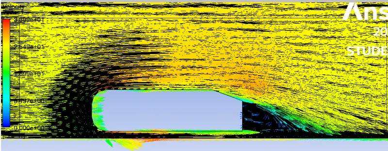
3. The vector plot clearly showing the wake region.
Pre-processing and solver setting
Geometry
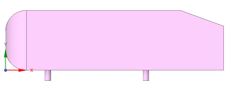
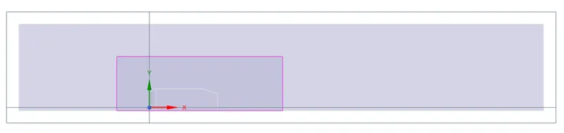
The geometry is symmetry condition so we cut it and perform the simulation with one half to reduce the computation time for simulatin . to create the computational domain create encloser over the doman with dimension of the given ahmed body with
creating the
mesh
case -1 (base mesh)
Target lenght = large enclosure =120 small enclosure = 60

create the infulation over the surface of the wall for the given viscous model
Boundary Condition
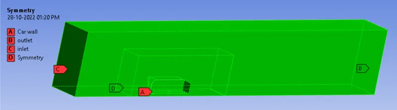
setup
|
Solver Type |
Pressure-Based |
|
|
Velocity Formulation |
Absolute |
|
|
Time |
|
|
|
Models |
Viscous model: K- epsilon standard enhance wall function |
|
|
Material |
Fluid type: Air |
|
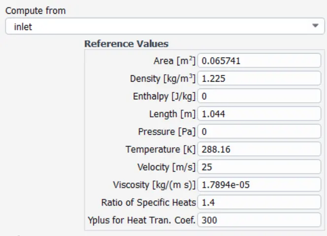
| Reference values | inlet |
INLET = velocity inlet = 25m/s
OUTLET = PRESSURE OUTLET
referance value for inlet
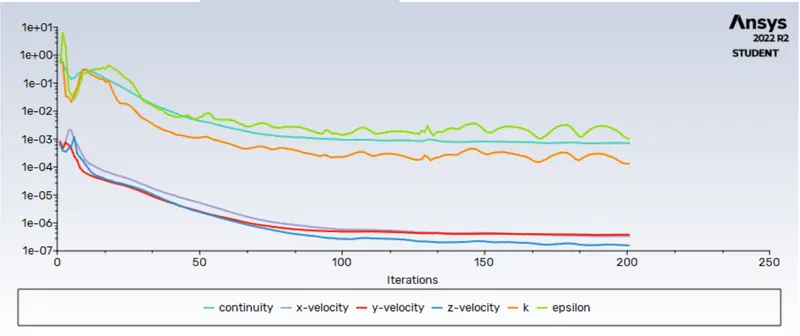
residual polts
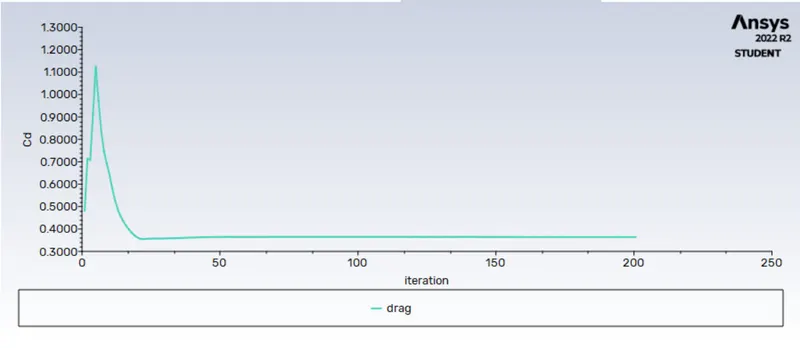
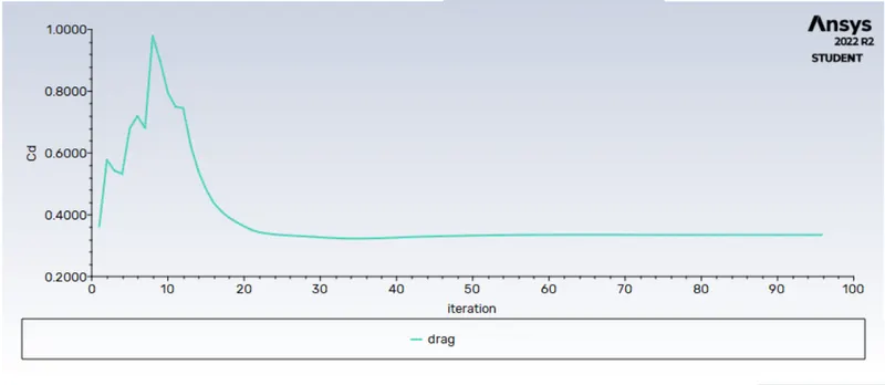
drag coefficient
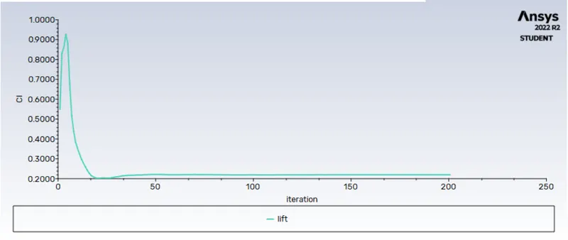
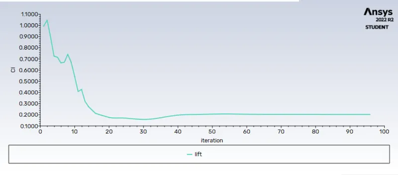
lift coefficient
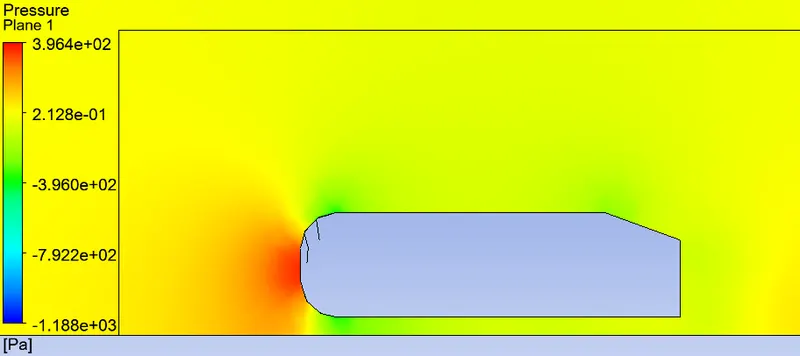
contour plot
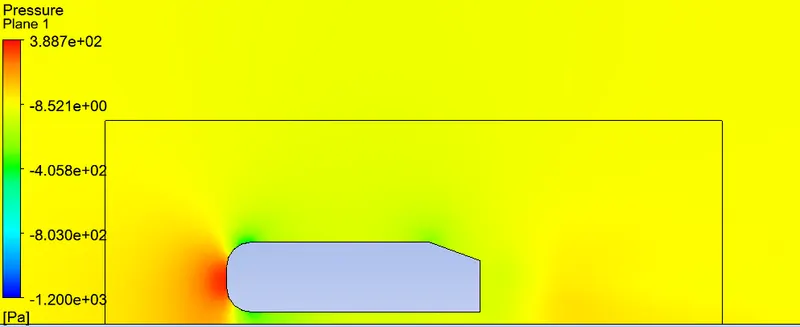
pressure
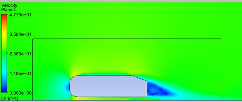
velocity
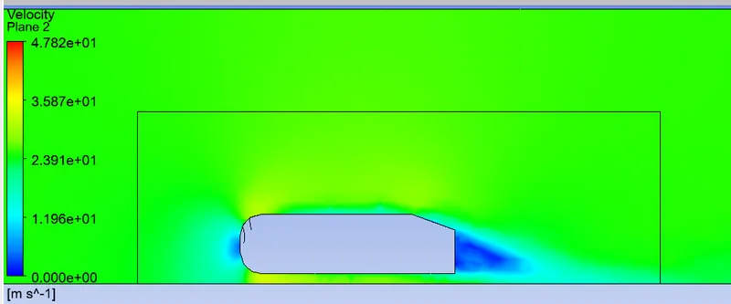
velocity vect
coefficient of lift = 0.2198
coefficient of drag = 0.3643
case -2
Target lenght = large enclosure =100 small enclosure = 50

residual plot
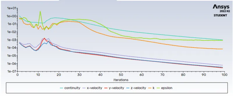
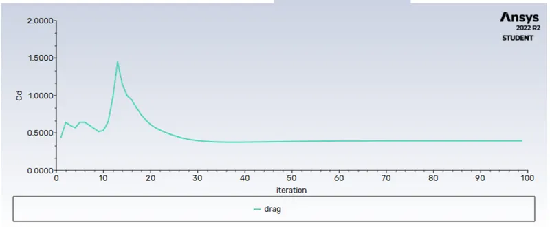
drag
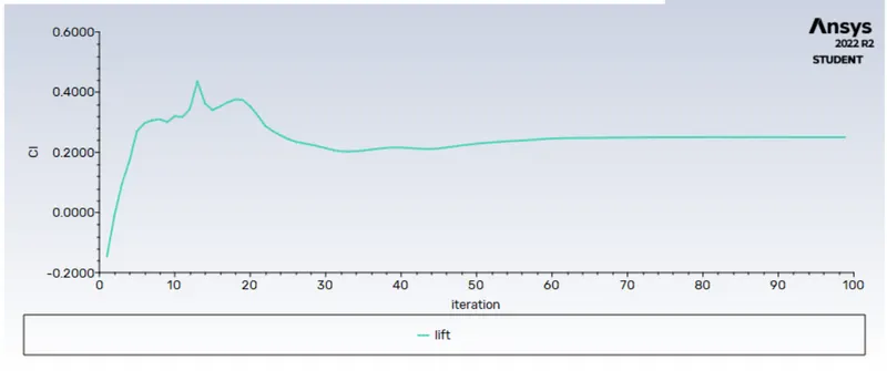
lift
contour plot
pressure
velocity
velocity vector
coefficient of lift = 0.2497
coefficient of drag = 0.3943
case - 3
Target lenght = large enclosure =90 small enclosure = 45

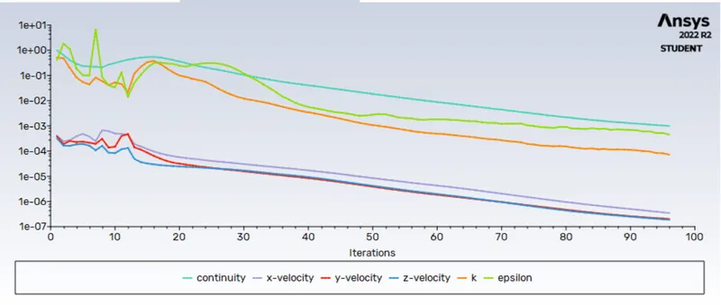
residual plot
drag
lift
contour plot
pressure
velocity
velocity vector
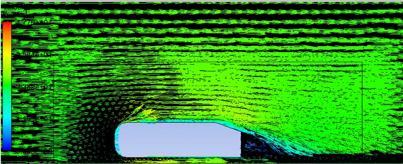
coefficient of lift = 0.2026
coefficient of drag = 0.3348
Comparison of all cases
| Steady-state, Turbulent flow, Density-based, Fluid material-Air | ||||
| Grid Independence Test | Turbulence-model | Number of elements | Lift-Coefficient | Drag-Coefficient |
| Baseline mesh | k -epsilon | 102628 | 0.2198 | 0.3643 |
| first refinement | k -epsilon | 147506 | 0.2497 | 0.3943 |
| Second refinement | k -epsilon | 354439 | 0.2026 | 0.3348 |
- It can be inferred that the grid independence test is performed to know the smaller cell size for convergence.
- Apart from mesh refinement, convergence depends on the Y+ value, inflation layer, it is advisable to use k-omega as the turbulence value because it calculates the values well near the wall.
- As the setup is refined drag coefficient, lift coefficient decreases.
- Y+ plays an important role in determining the value of drag.
- The negative pressure in the wake region is primarily because there is no flow in that region. This can be further attributed to various factors such as separation and recirculation which is evident from the vector plot near the wake region.
- The point of separation occurs at the rear end of the vehicle, the separation occurs beyond this point where it can be observed that the flow recirculates and attaches it to the boundary layer.