Week 3 - External flow simulation over an Ahmed body.
AIM
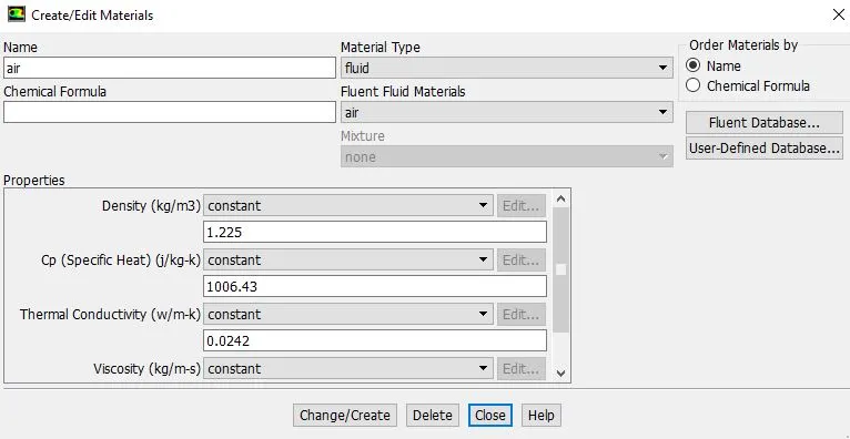
Simulate the external flow over an Ahmed Body. To run the simulation for the velocity of 25 m/sec with the default air properties in fluent.
AHMED BODY
The Ahmed body is a generic car body (a simplified vehicle model). The airflow around the Ahmed body captures the essential flow features around an automobile and was first defined and characterized in the experimental work of Ahmed . Although it has a very simple shape, Ahmed body allows us to capture characteristic features that are relevant to bodies in the automobile industry. This model is also used to describe the turbulent flow field around a car-like geometry. Once the numerical model in validated, it is used to design new models of the car. The rear part of Ahmed body called as 'slant angle' which influences drag and lift with its critical slant angle which is around 0-30 degree.
Some of the importance of the ahmed body is;
- Ahmed Body plays a vital role in testing the aerodynamic properties of vehicle.
- It is also used to describe the turbulent flow field around a car(like geometry) and later to design new car models with validated results.
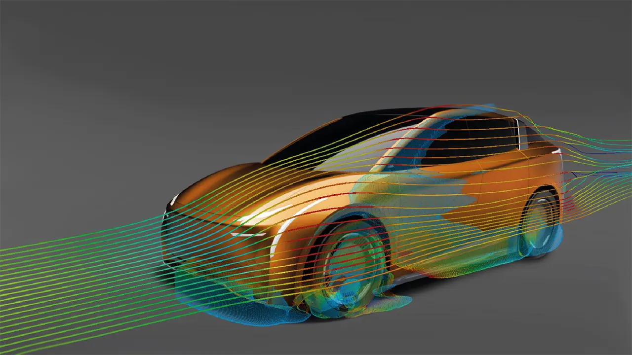
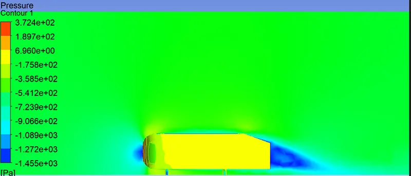
Negative pressure in the wake region.
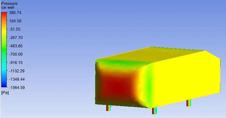
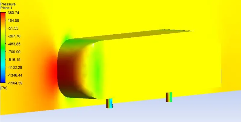
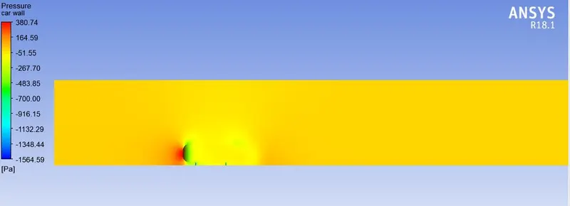
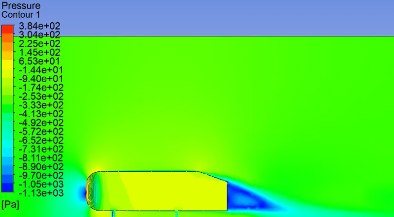
- The negative pressure in the wake region the fluid as it flows Ahmed body there would be stagnation of air particles at the front of the Ahmed body and pressure would be more and which can be seen from the pressure contour, then there would be gradual increase in the acceleration of the air particles till the start of the slant angle
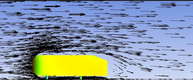
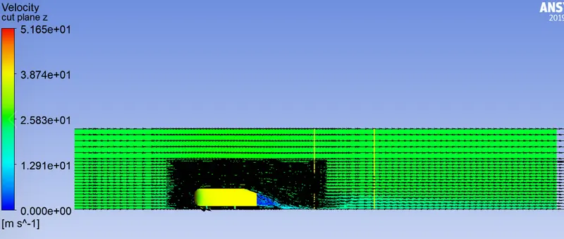
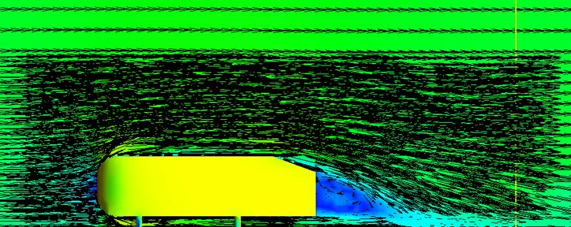
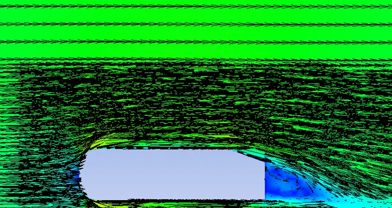
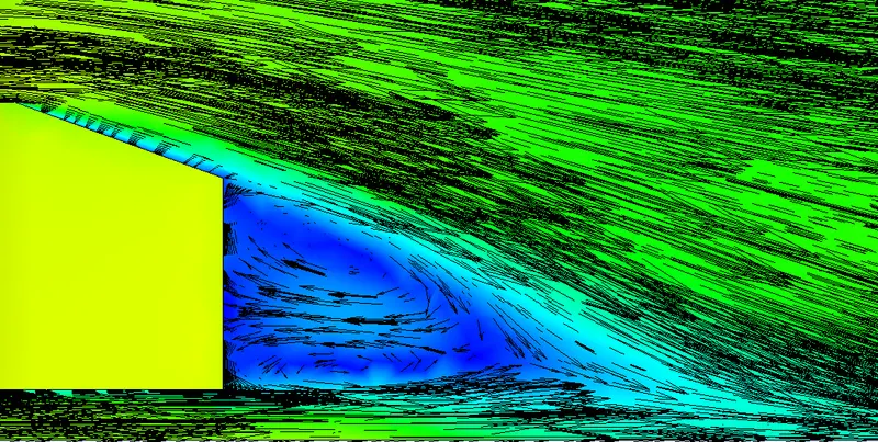
- Reason for negative pressure in the wake region: The path lines showing the exact circular motion or vorticity generation just at the rear end of the car. The separation takes two regions of distribution. One at the upper part of the rear and the other at the lower part of the rear end.
- The flow around the vehicle is characterized by high turbulent and three-dimensional flow separations as well as there is a growing need for more insight into the physical features of these dynamical flows.
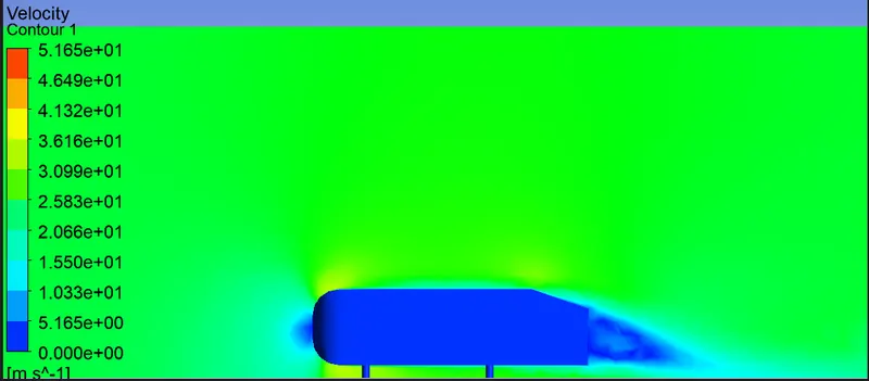
- At some point, the velocity gradient becomes zero, which is the point where the flow separates or detaches. Beyond this point, the velocity profile is zero both at the wall, because of the no-slip condition, and at the inflection point, which is where the velocity crosses from negative into positive. In the negative velocity region, between the surface and the inflection point, the air flows in a direction opposite to the main flow – this is called a recirculation. The separated flow will now surf on top of this recirculation flow and the boundary layer and wake will continue to grow, which can have a negative effect on drag.
Significance of the point of separation.
- Boundary layer seperation happens due to the flow which doesn't follows the solid body(ahmed body) regarding the shape of the solid body which where the seperation or detachment of flow starts ,in that region vortices and eddy forces will form, we can also see wake region and negative pressure in that region.
Case-1: Base line simulation
At first only a basline simulation is done to anlyse the aerodynamic characteristics of the ahmed body, based on the generated results, the body is further refined.
Geometry
- Open the geometry.
- Import the ahmed body in asnsys spaceclaim.
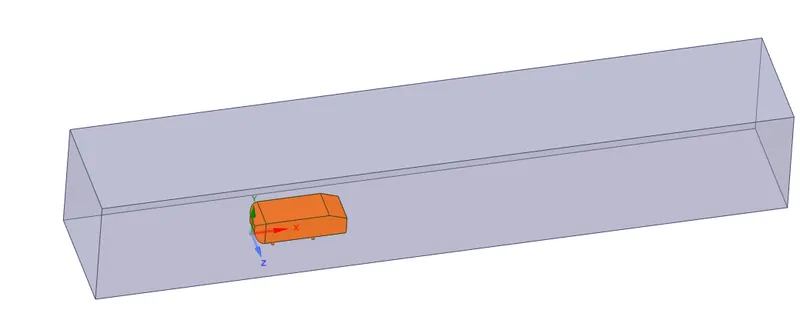
- Provide enclosure to the ahmed body.
- Supress the ahmed body.
Mesh Generation
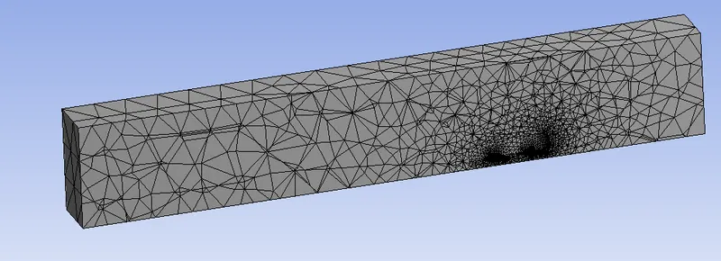
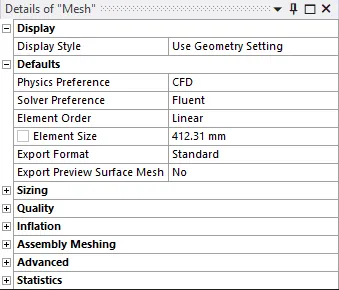
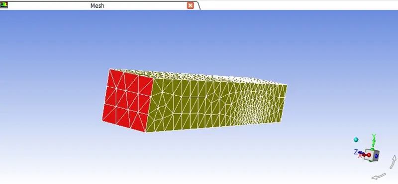
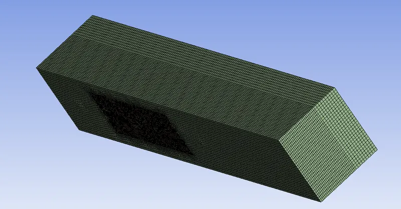
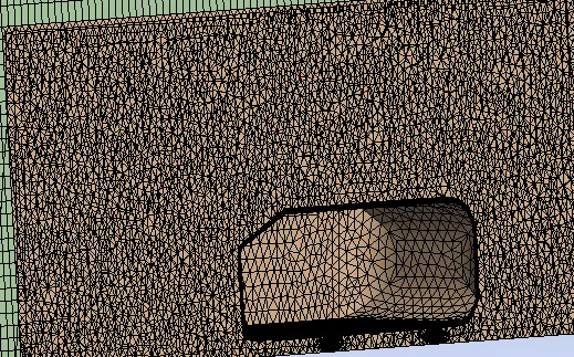
- Inorder to evaluate at first, only a baseline mesh is done, the below represents the generated mesh. The details of the mesh with an element size is shown and also the statistics is shown below.

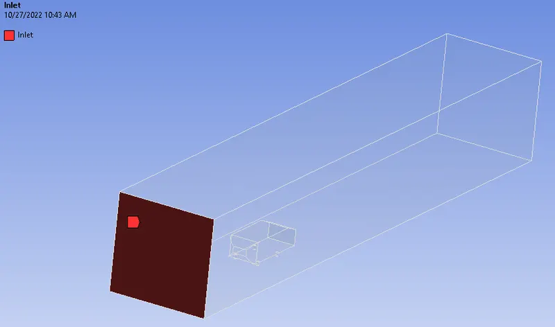
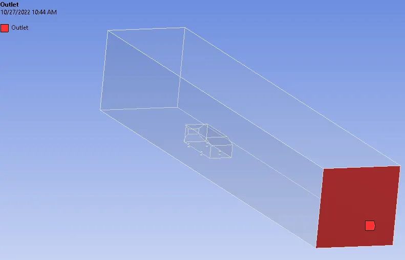
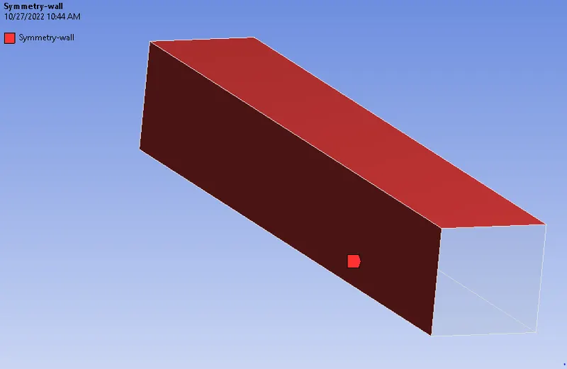
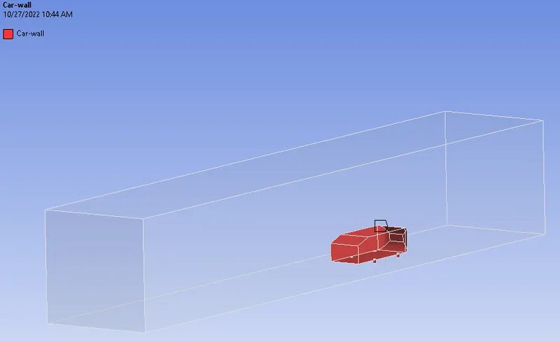
- After the mesh is generated, the boundaries are named as inlet, outlet, symmetry-wall and car wall.
- The named selections are shown below,
Inlet
Oulet
Symmetry-wall
Car wall
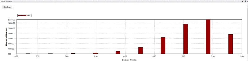
- The Mesh metrics is shown below;
Setup
- First, we need to check the mesh, from the check mesh from domain section.
- Secondly, check whether the boundaries are mentioned correctly;
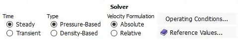
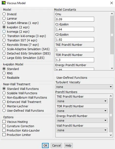
- Set the turbulence model, here in baseline simulation using the K-epsilon model.
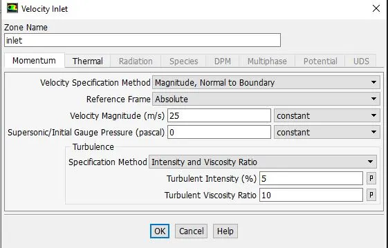
- Now set the boundary conditions by giving an inlet velocity of 25m/s
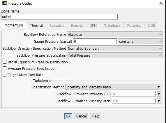
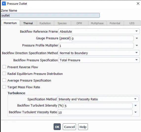
- Oulet gauge pressure is 0 pa.
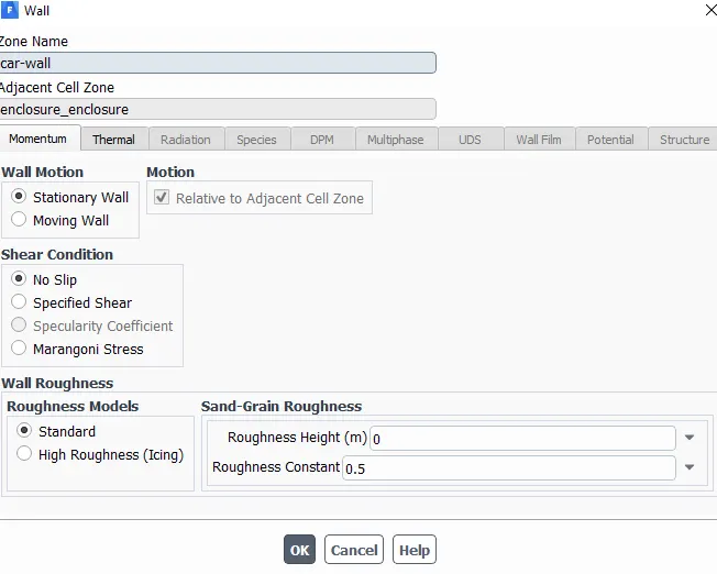
- car wall with no slip condition.
- Create the lift and drag coefficient plots from solution method.
- Now, go to the results section and create a plane at some distance normal to x,y,z axis
- Initialize the problem with Hybrid Initialization.
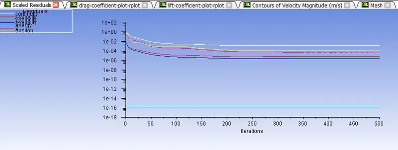
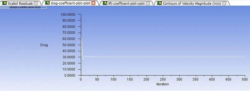
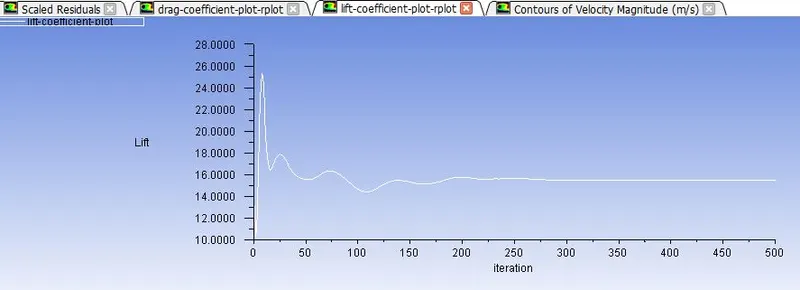
- Finally simulate the problem for some amount of iteration and ovserve the Drag, Lift and Residual plots.
Results
Residuals
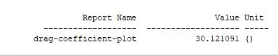
Drag Coefficient
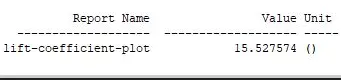
Lift Coefficient
Contours, plots and Vectors
Pressure contour:
Car wall
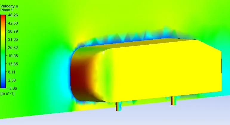
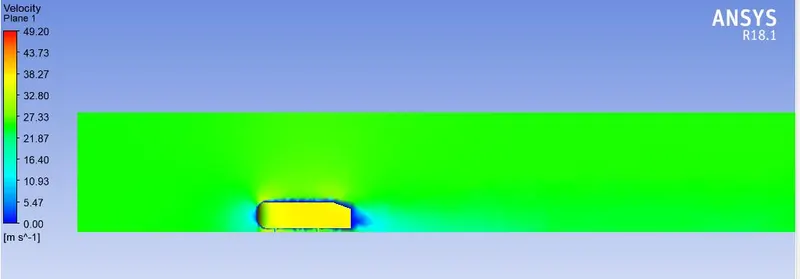
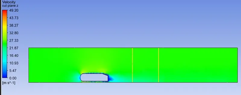
Velocity Contour
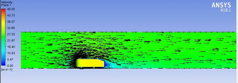
Vector plot
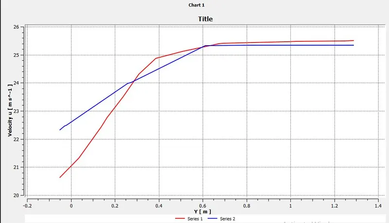
Case-2: Refined simulation with Y+
Geometry
- Open the geometry.
- Import the ahmed body in asnsys spaceclaim.
- Provide enclosure to the ahmed body(inner and outer) according to given dimensions.
- Supress the ahmed body.
- Input Planes & select XY plane and view the interference range.
- Now, go to prepare and check for interference and correct it.
- Set the topology to share.
- Hence completes the geometry setup.
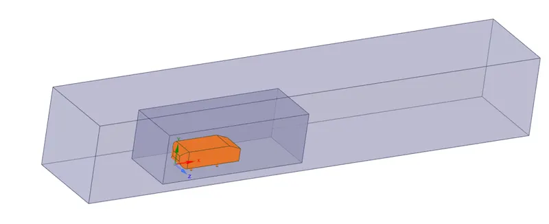
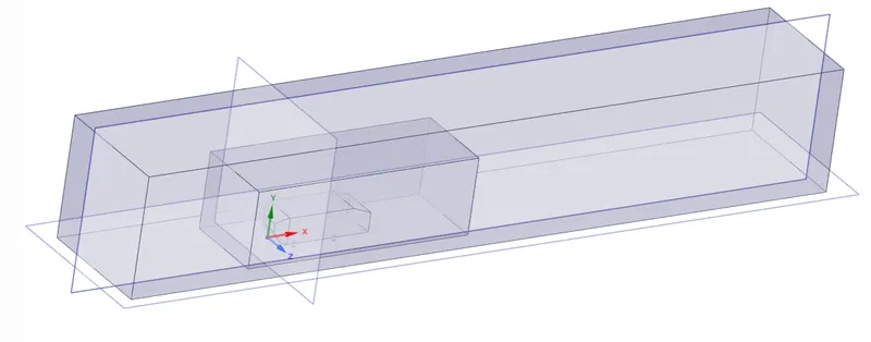
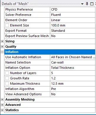
Mesh Generation
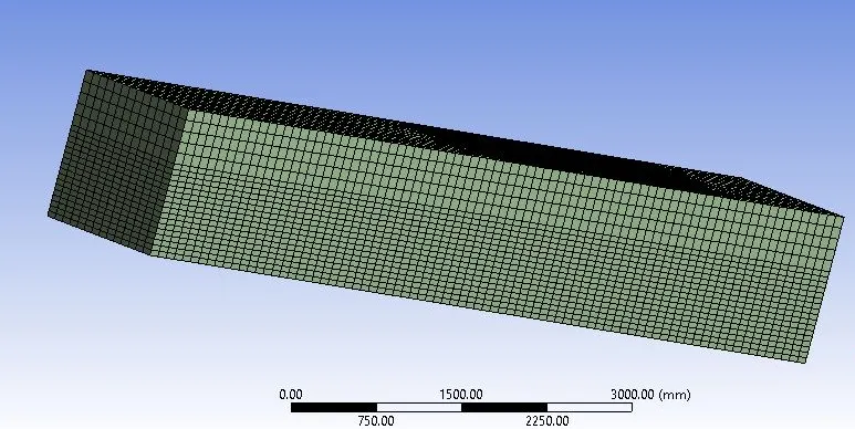

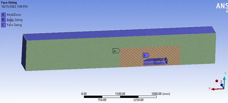
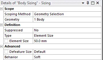
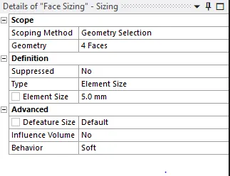
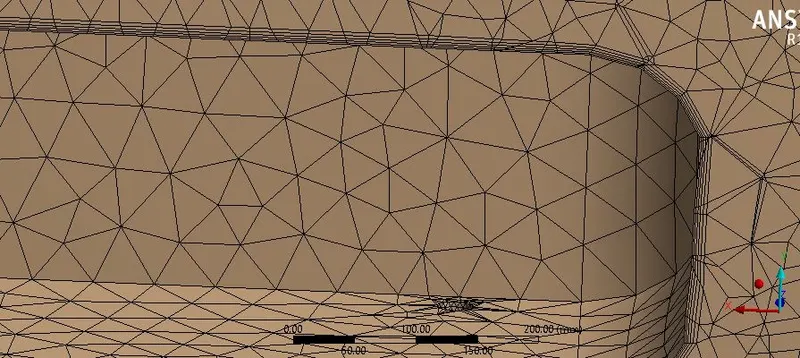

Setup
- First, we need to check the mesh, from the check mesh from domain section.
- Secondly, check whether the boundaries are mentioned correctly;
- Set the turbulence model, here in baseline simulation using the K-Omega SST model.
- Now set the boundary conditions by giving an inlet velocity of 25m/s
- Oulet gauge pressure is 0 pa.
- car wall with no slip condition.
- Create the lift and drag coefficient plots from solution method.
- Now, go to the results section and create a plane at some distance normal to x,y,z axis
- Initialize the problem with Hybrid Initialization.
- Finally simulate the problem for some amount of iteration and ovserve the Drag, Lift and Residual plots.
Results
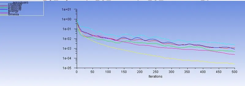
Residuals
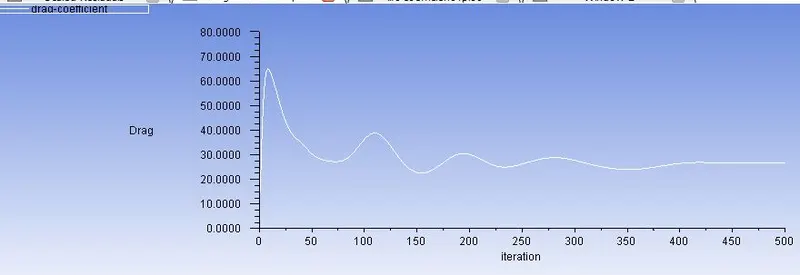
Drag Coefficient

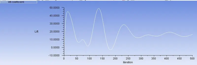
Lift Coefficient

Contours, plots and Vectors
Pressure contour:
Velocity Contour
Vector plot
Case-2a: Refined simulation with Y+
Geometry
- Open the geometry.
- Import the ahmed body in asnsys spaceclaim.
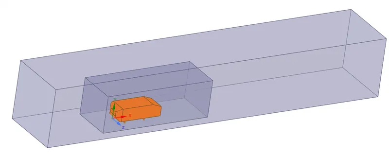
- Provide enclosure to the ahmed body(inner and outer) according to given dimensions.
- Supress the ahmed body.
- Input Planes & select XY plane and view the interference range.
- Now, go to prepare and check for interference and correct it.
- Set the topology to share.
- Hence completes the geometry setup.
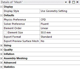
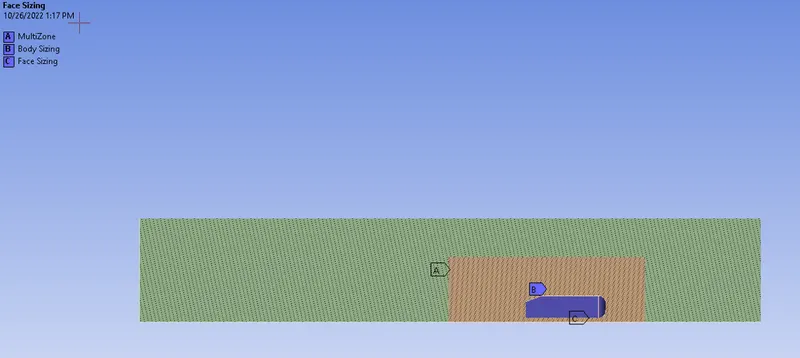
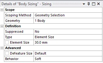
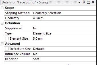
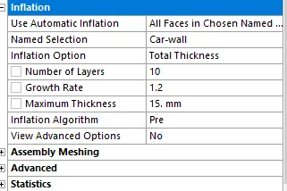
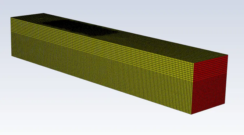
Mesh Generation

Setup
- First, we need to check the mesh, from the check mesh from domain section.
- Secondly, check whether the boundaries are mentioned correctly;
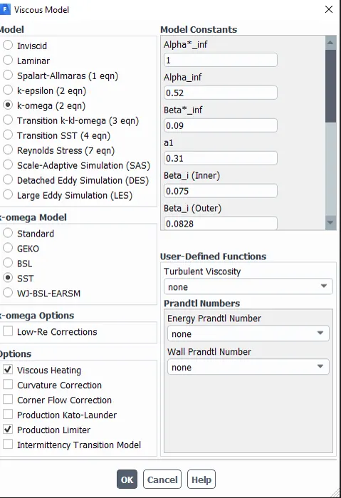
- Set the turbulence model, here in baseline simulation using the K-Omega SST model.
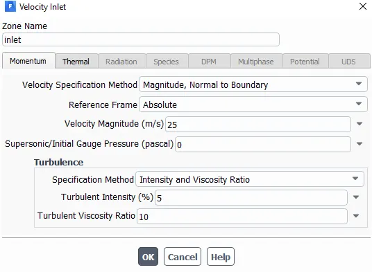
- Now set the boundary conditions by giving an inlet velocity of 25m/s
- Oulet gauge pressure is 0 pa.
- car wall with no slip condition.
- Create the lift and drag coefficient plots from solution method.
- Now, go to the results section and create a plane at some distance normal to x,y,z axis
- Initialize the problem with Hybrid Initialization.
- Finally simulate the problem for some amount of iteration and ovserve the Drag, Lift and Residual plots.
Results
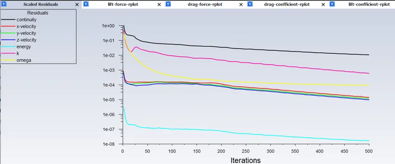
Residuals
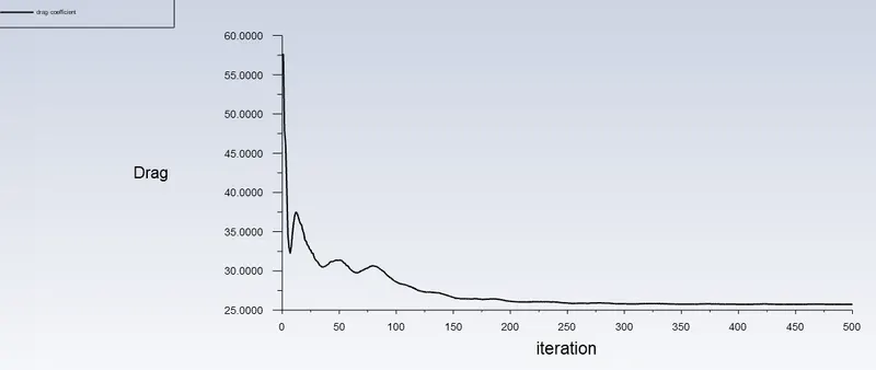
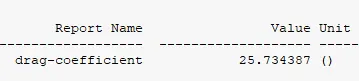
Drag Coefficient

Contours, plots and Vectors
Pressure contour:
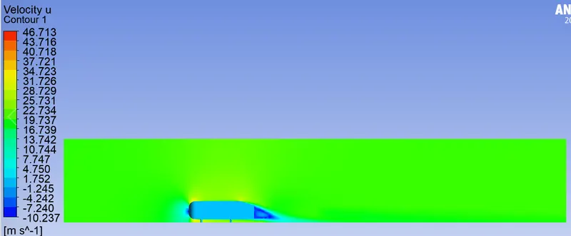
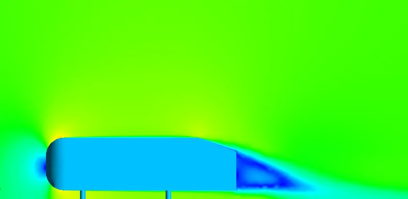
Velocity Contour
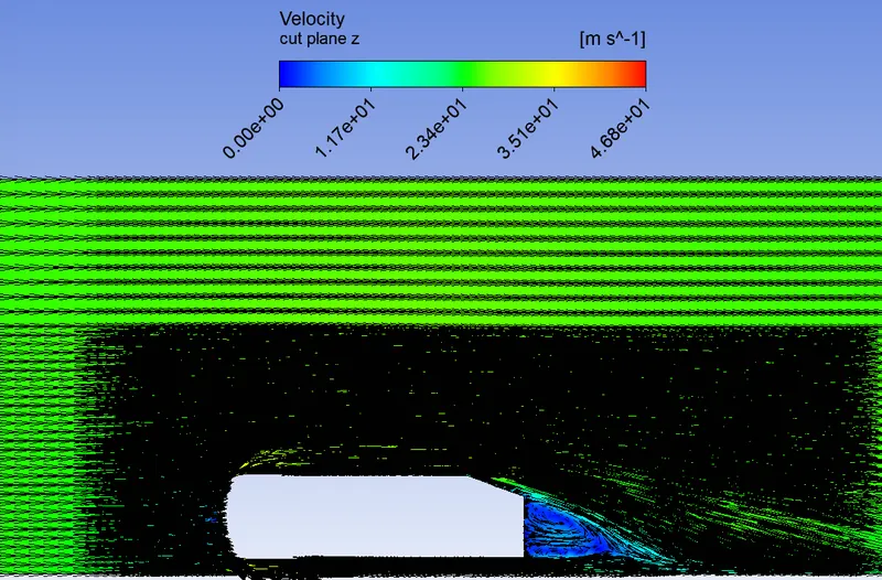
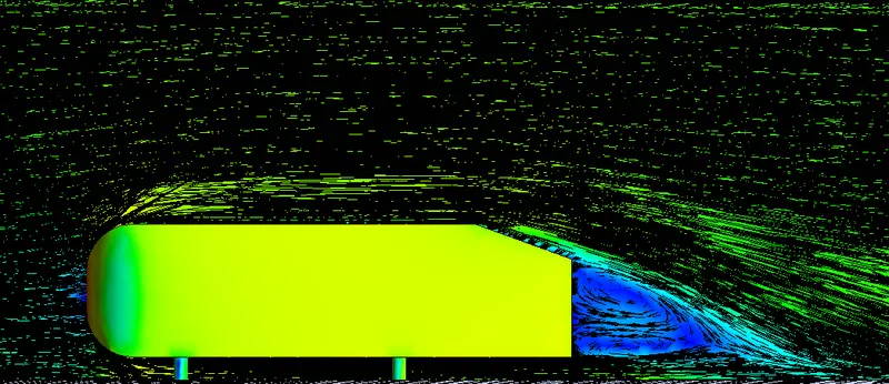
Vector plot
Conclusions
- Here we use computational fluid dynamics (CFD) to illustrate flow separation for the case of flow over a Ahmed body along a wall. The flow is steady and twodimensional and vector plot shows outer flow velocity vector generated by a solution of the Navier-Stokes equation.
- Here we can see the regions behind the body where wakes are formed, circling regions where low velocity which induce a considerable amount of velocity drag on the body.
- The full (laminar) Navier–Stokes equation is solved, the viscous terms lead to flow separation off the rear end of the body, as seen in vector plot.
- The dashed black line is a type of dividing streamline. Fluid below this streamline is caught in the separation bubble, while fluid above this streamline continues downstream.
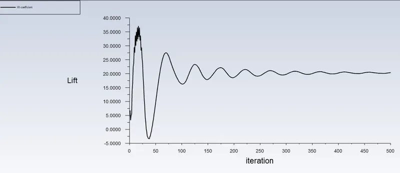
- Grid Depedence Test was conducted, an additional observation was also made, i.e; the drag coefficient decreases and the lift coefficient increases as number of elements increases. This decrease is very small and may be considered insignificant.