Week 3 - External flow simulation over an Ahmed body.
AIM:- External flow simulation over an Ahmed body.
Objective:-
The objective of this work is to numericall investigated the Aerodynamic behaviour using commercial tool ANSYS FLUENT of a simplified car model called Ahmed body widely used in the automotive industry for validating simulation tools or aerodynamic drag and lift. In this problem, we have considered half model of the ahmed body as the body is perfectly symmetric. This is the best practice where we can save on the number of cells and get the results faster as well.
Perform the grid independency test and calculated the drag and lift coefficient for each case while maintaining y+ in appropriate region.
Validated the results aginst the experimental data to ensure the accuracy and stability of the solution.
Theory:-
Ahmed Body-
As the burning of fossil fuels becomes a more pressing issue, manufacturers are introducing more fuel-efficient cars to the market. One main contributor to fuel burn is the car’s aerodynamic drag. Complexly shaped, cars are very challenging to model and it’s difficult to quantify the aerodynamic drag computationally. The Ahmed body is a benchmark model widely used in the automotive industry for validating simulation tools.The Ahmed body is a benchmark model widely used in the automotive industry for validating simulation tools. The Ahmed body shape is simple enough to model, while maintaining car-like geometry features.
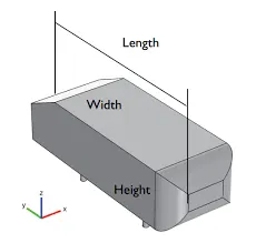
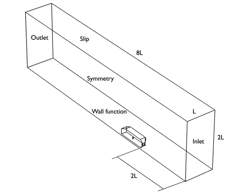
The aim is to simulate the model on computational fluid dynamics (CFD) software(Ansys Fluent) and compare the Drag Coefficient, Velocity Profiles, Velocity field, and the time-averaged Wake structure of the CFD simulation results with the real experimental measurement in the wind tunnel.
Modeling Approach-
Ansys Fluent as CFD software is used to solve for Ahmed body external flow.
Geometry-
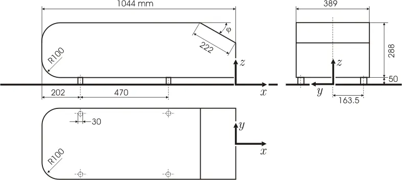
The simple geometrical shape has a length of 1.044m, height of 0.288m and width of 0.389m. The shape of cylinderical pillars that is attached to the bottom of the body has a dimension of 0.5 m and the slant height of the rear surface ϕ=30°.The Ahmed body with the slant angle of 25° belongs to the fastback vehicles, which exhibit very strong inward rotating longitudinal vortices at the C-pillars.
Step 1 : Pre-processor in Ansys Spaceclaim
The original CAD model of the Ahmed body is imported in SpaceClaim which was in the STEP file format. Original STEP files are usually too complex for comprehensive CFD simulations, so certain preprocessing (cleaning) CAD work is generally required.
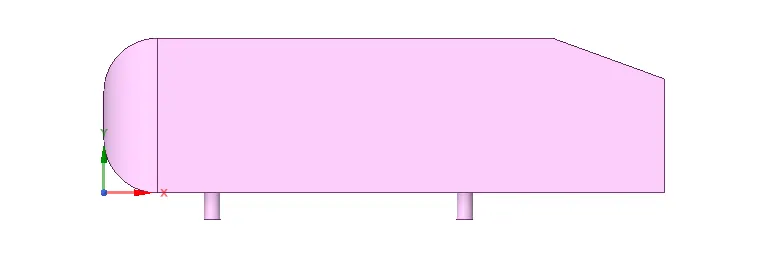
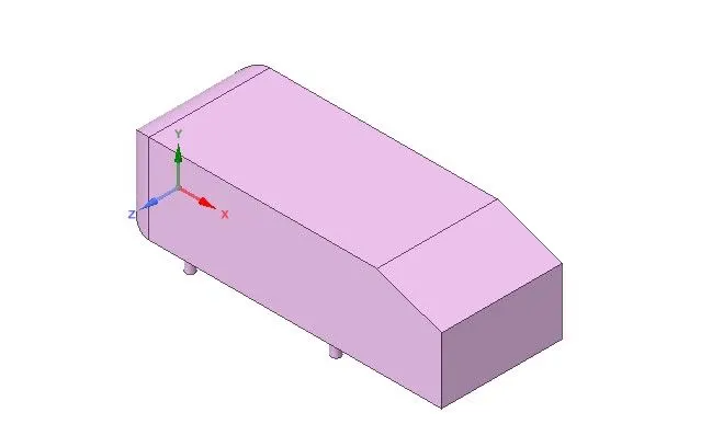
Front view of ahmed body car Asometric view of ahmed boby car
- Creating Enclosure (Wind Tunnel)- We have created two enclosure . A flow domain is created, the front of the body is placed at a distance of 2m from the flow inlet.
This acts as a Real-time wind tunnel for our computational solution. Also, a small enclosure is then created around the model in order to capture the physics more accurately around the model.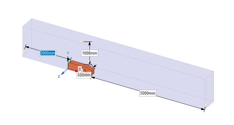
- Splitting the model - To reduce the computational cost, the asymmetry plane is introduced to simulate half of the model.Then we have created a plane and split the symmetry model into two half using split tool.
- Select a plane perpendicular to the Ahmed body and check the interference in the cross sectional view and then resolved the interference problem by the interfernce command line.
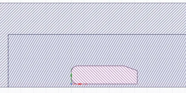
- After the solution of the interference problem do not forget to share the fluid properties of fluid flow in the 2 enclosure's by the share topology command.
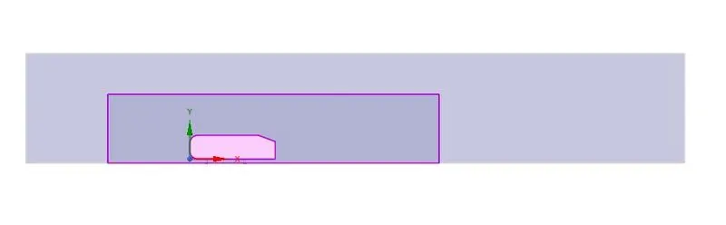
Mesh :
- First, we will name the face as inlet, outlet, symmetry, and car wall.
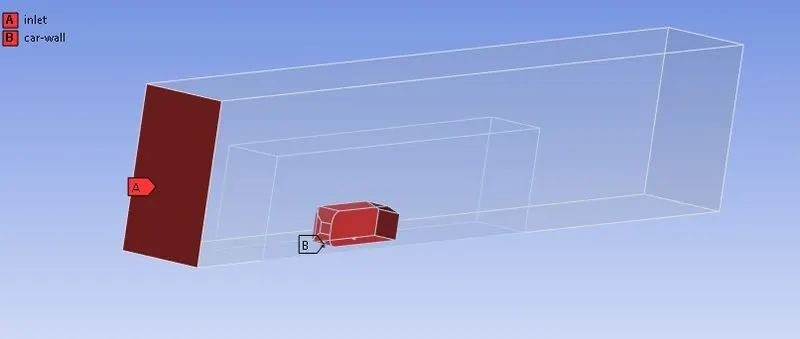
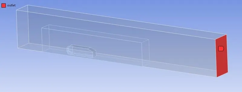
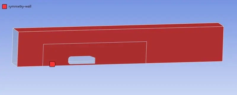
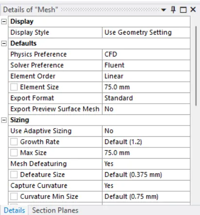
- After that first we generate default mesh of element size is 409 mm.
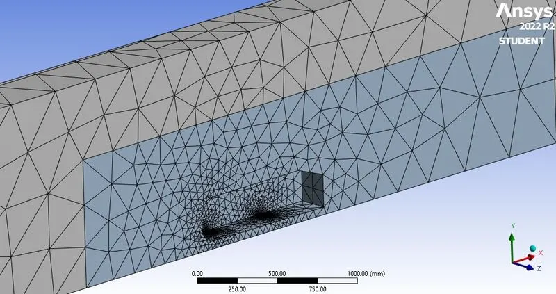
- Next, as the enclosure is perfectly rectangle so for this it is better to go for the hexahedral or multizone mesh. It will give better mesh quality also decrease the number of total element counts. So, we have to go insert sizing and select the multizone for the different different mesh patterns. It will generate hexahedral baseline automatically bcoz hexahedral meshes are more accurate that tetrahedral meshes.
Setup-
- in the setup>physics>steady state and density-based solver.
- setup>physics>viscous model>k-omega>ok.
- setup>physics>materials, select air as a flow material>ok
- setup>physics>boundaries>inlet -velocity as 25 m/s, outlet gauge pressure as 0, other conditions will be the default values we are considering>click on ok
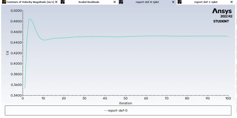
- setup>solution>report>definitions>new>force report>drag>drag coefficients>car-wall>select report file and report plot >save/display
- setup>solution>method>Hybrid>initialize
- Result>create>plane>point and normal>ok
- setup>solution>run calculation
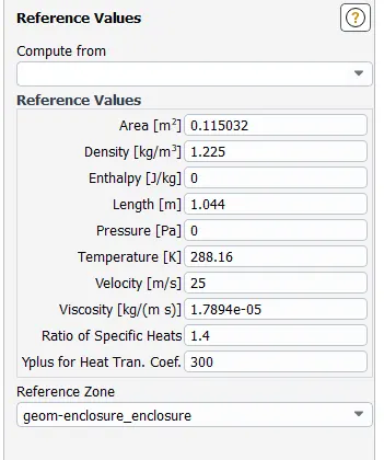
DO NOT FORGET TO GIVE REFERENCE VALUES
SOLUTION
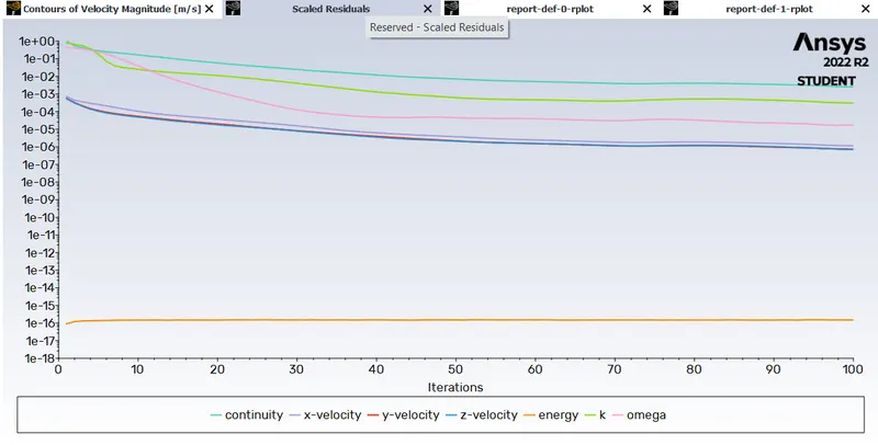
1. Residuals
2. Drag co-efficient
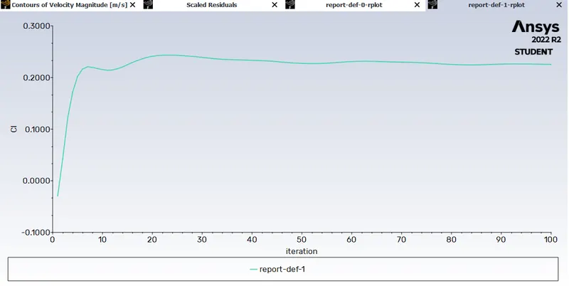
3. Lift co-efficient
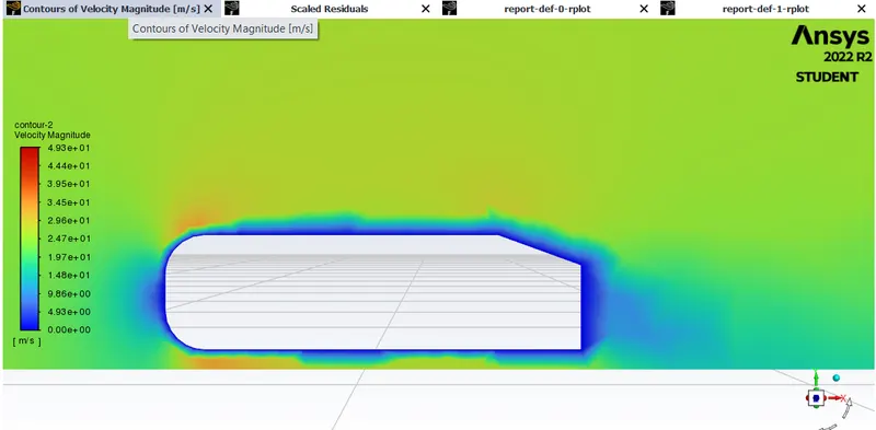
4. Velocity contour
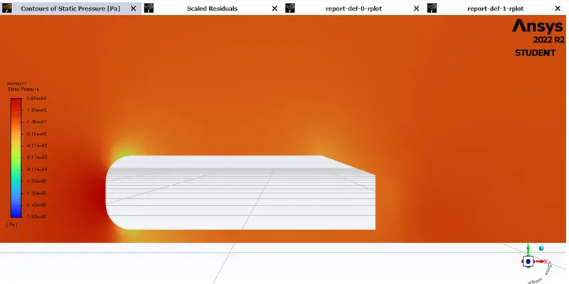
5. Pressure contour
RESULTS:
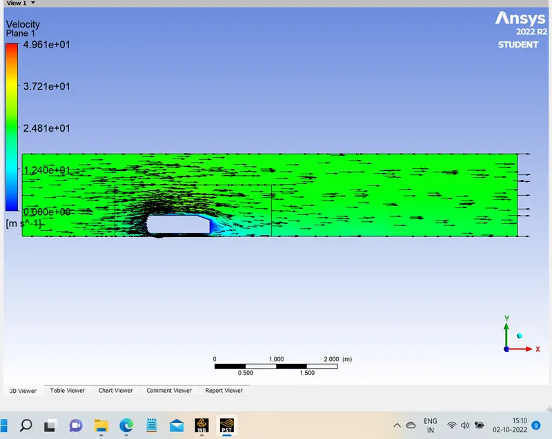
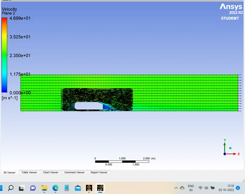
1. Vector on xy plane
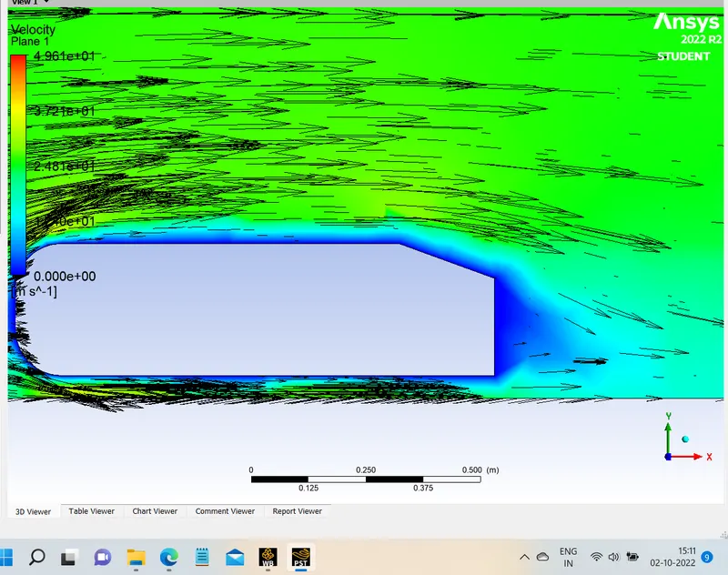
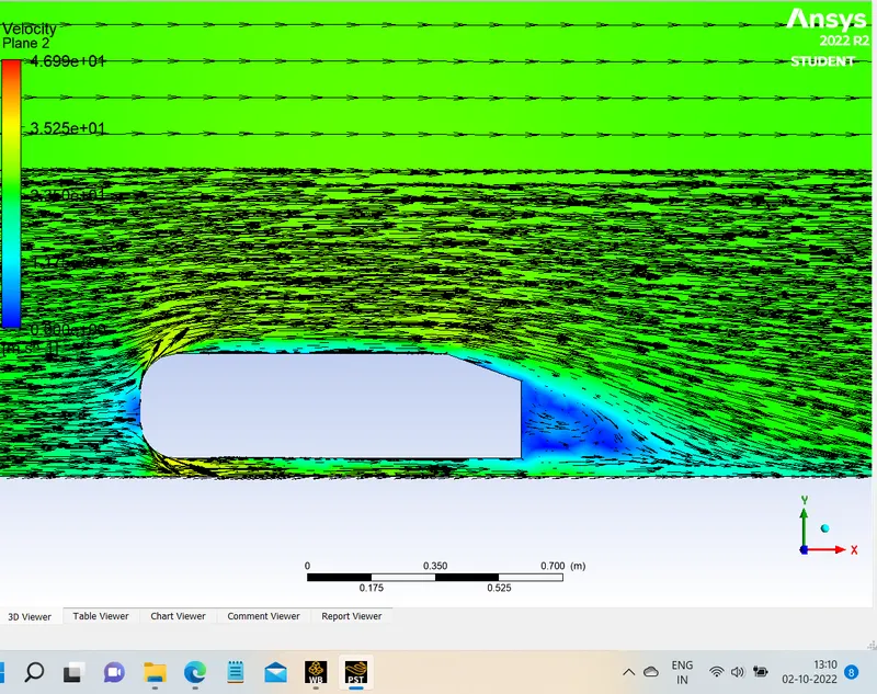
zoomed in for better understanding of vectors
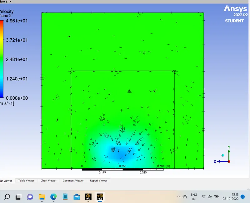
2. Vectors on yz plane 200mm after the ahmed body
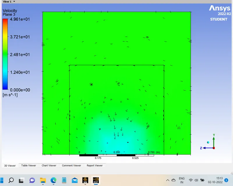
3. Vectors on yz plane 400mm after the ahmed body
Case 2 : Slightly Refined mesh
- Y-plus = 100
- Viscous model: K-omega
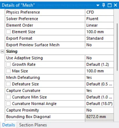
- 1st box domain =100 mm size of hexahedral mesh
- 2nd box domain = 50 mm size of tetrahedral mesh
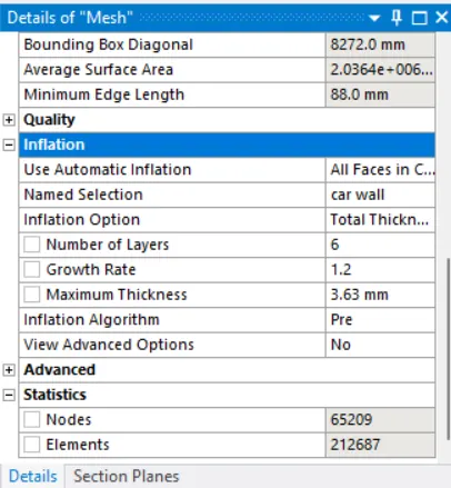
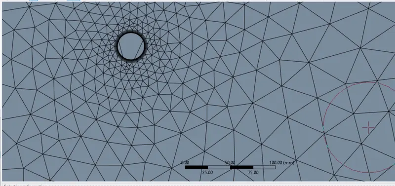
- Inflation layer thickness = 6 layers, 3.63mm total thickness
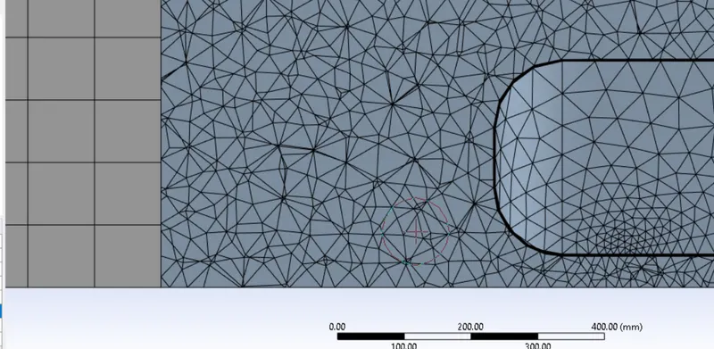
- Elements = 212,687
- Nodes = 65,209
MESH
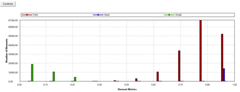
Quality of mesh
SET UP
- same for every case
SOLUTION
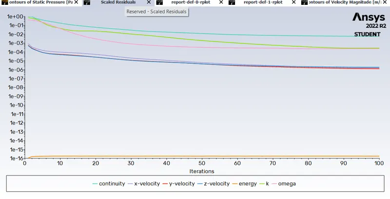
1. Residuals
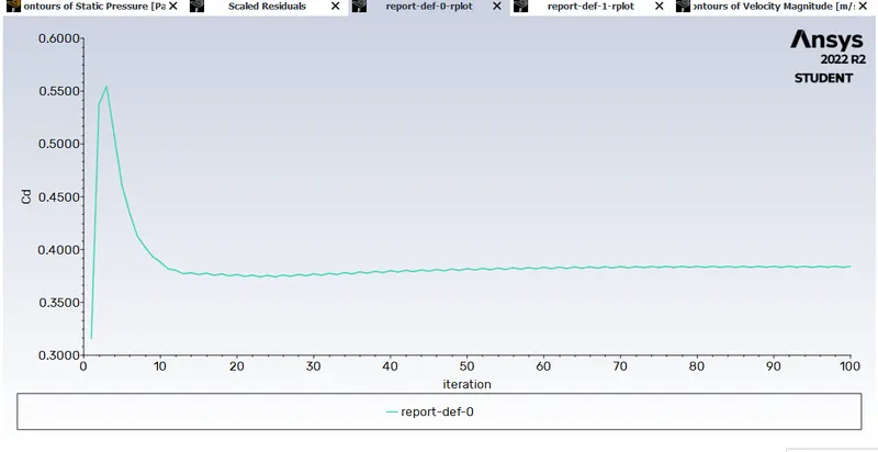
2. Drag co-efficient
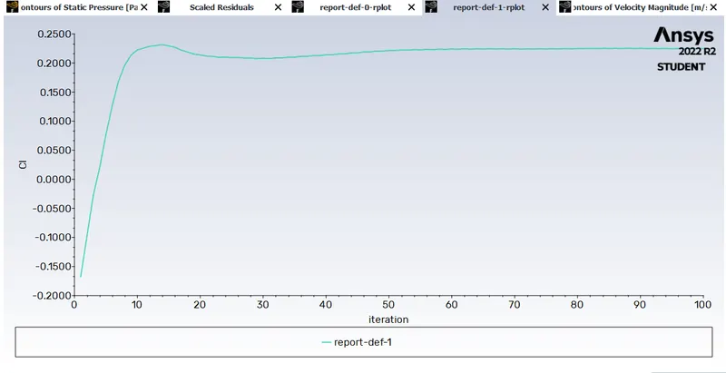
3. Lift co-efficient
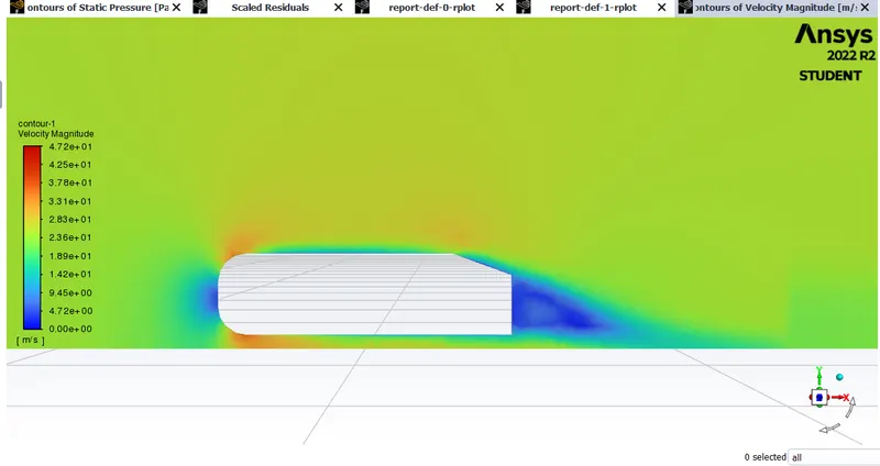
4. Velocity contour
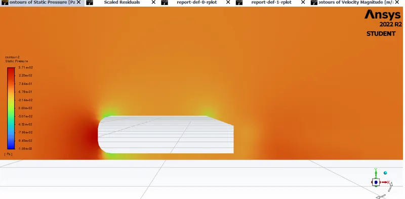
5. Pressure contour
RESULTS:
Vector on xy plane
zoomed in for better understanding of vectors
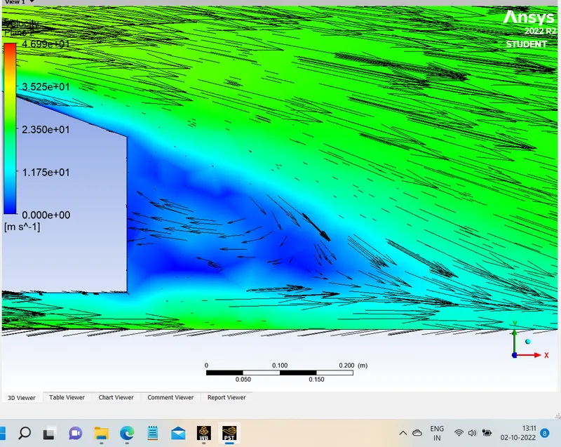
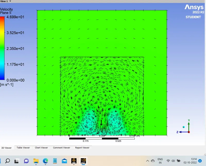
Vectors on yz plane
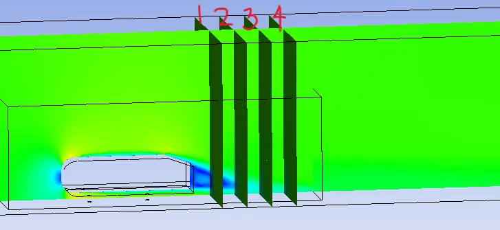
- 200mm after the ahmed body
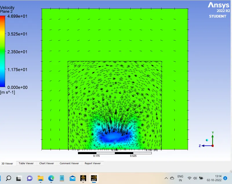
- 400mm after the ahmed body
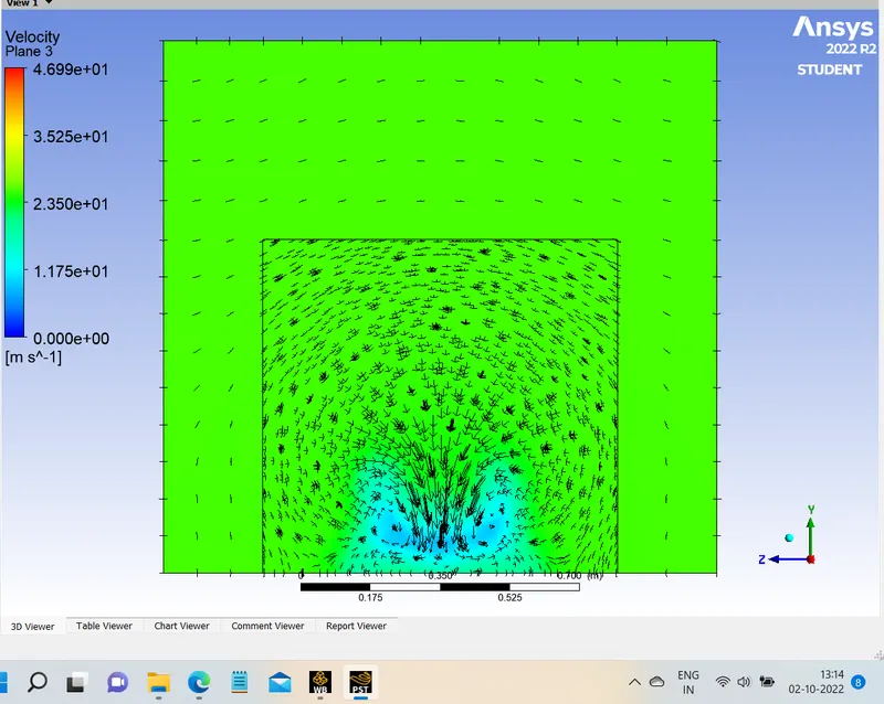
- 600mm after the ahmed body
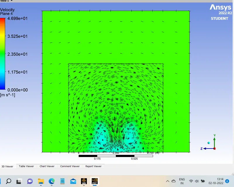
- 800mm after the ahmed body
Case 3 : More Refined mesh
- Y-plus = 100
- Viscous model: K-omega
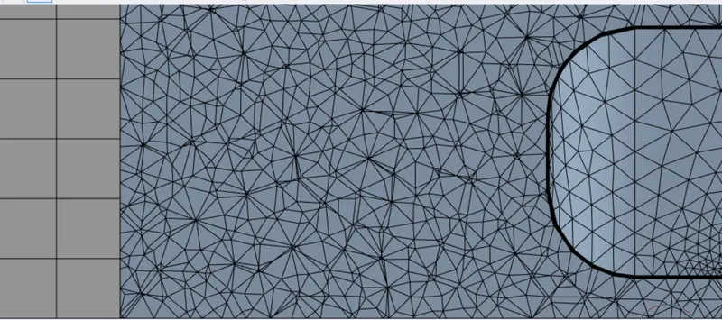
- 1st box domain =75 mm size of hexahedral mesh
- 2nd box domain = 35 mm size of tetrahedral mesh
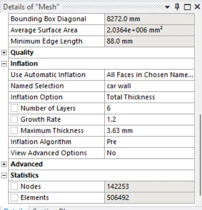
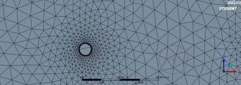
- Inflation layer thickness = 6 layers, 3.63mm total thickness
- Elements = 506,492
- Nodes = 142,253
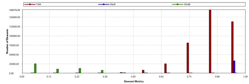
MESH
Quality of mesh
SET UP
- same for every case
SOLUTION
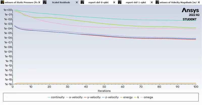
1. Residuals
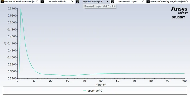
2. Drag co-efficient
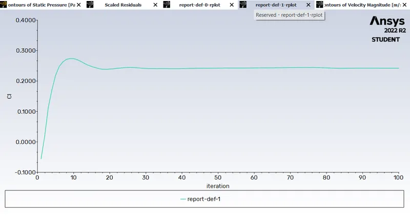
3. Lift co-efficient
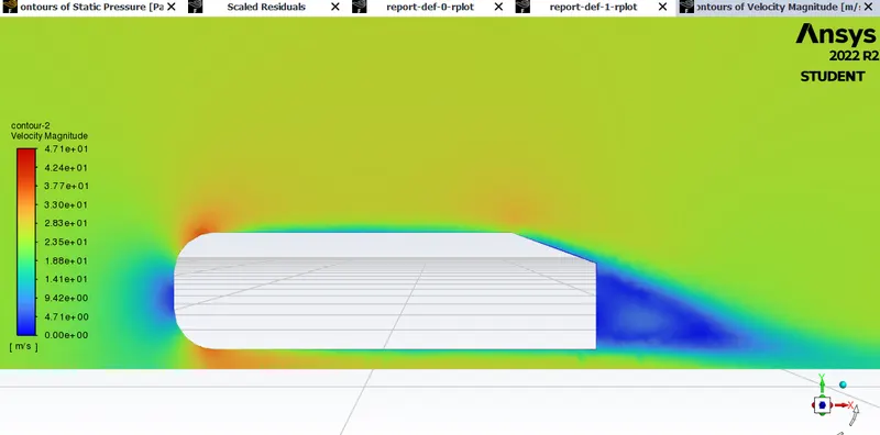
4. Velocity contour
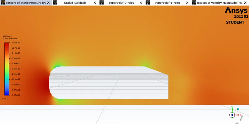
5. Pressure contour
RESULTS:
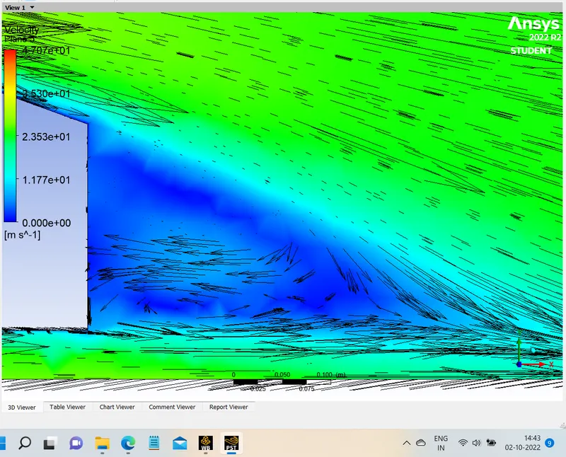
Vector on xy plane

zoomed in for better understanding of vectors
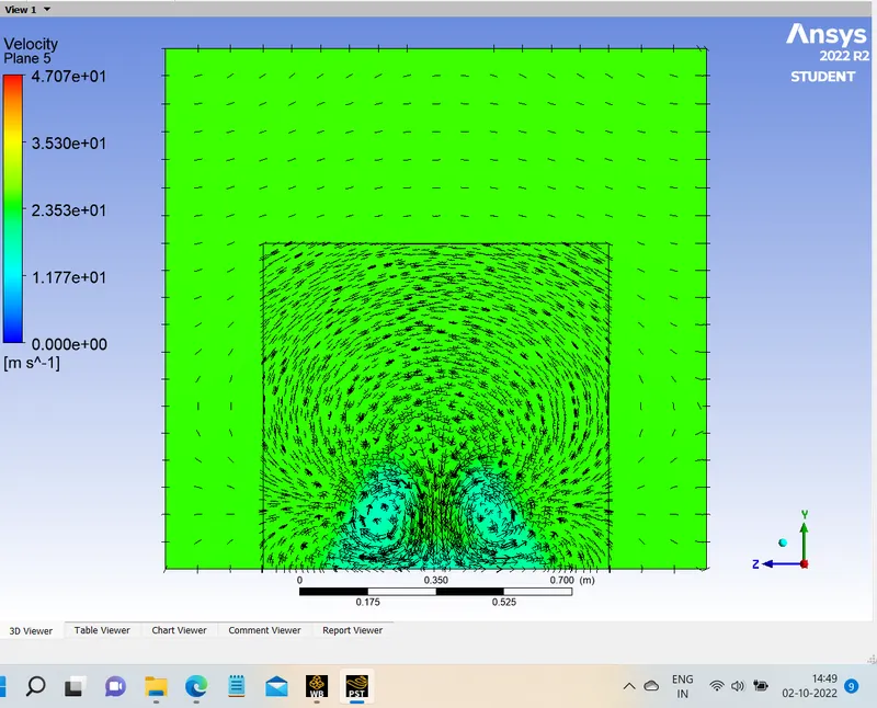
Vectors on yz plane
- 200mm after the ahmed body
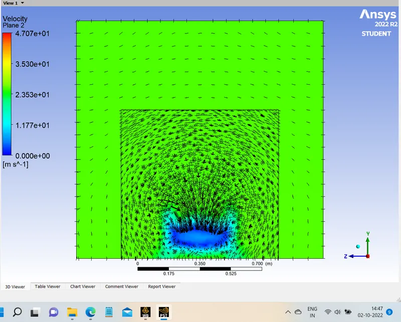
- 400mm after the ahmed body
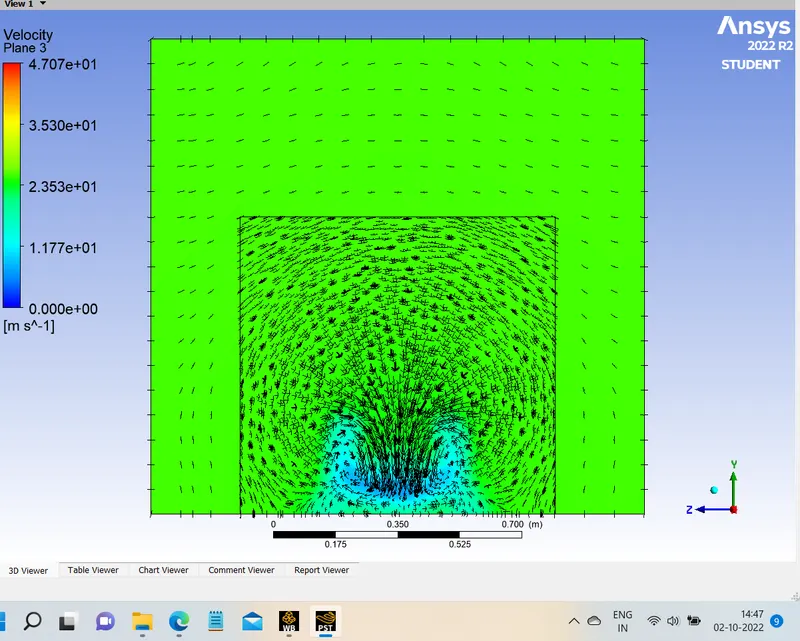
- 600mm after the ahmed body
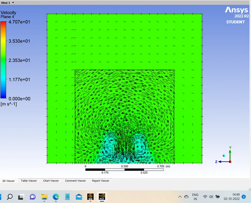
- 800mm after the ahmed body
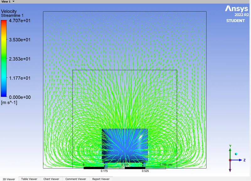
STREAMLINE VIEW :
Negative pressure gradient
When fluid velocity increases, the pressure decrease. The wake region is formed due to adverse pressure in the rear end causes the boundary layer to separate out from the body. The wall shear stress and velocity becomes zero and wake formation starts. These wakes are nothing but small vortices that create negative pressure. These create circulation of velocity and induces drag forces.
Point of seperation
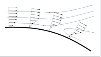
Separation occurs due to an adverse pressure gradient encountered as the flow expands, causing an extended region of separated flow. The part of the flow that separates the recirculating flow and the flow through the central region is called the dividing streamline. The point where the dividing streamline attaches to the wall again is called the reattachment point. As the flow goes farther downstream it eventually achieves an equilibrium state and has no reverse flow.When the boundary layer separates, its remnants form a shear layer and the presence of a separated flow region between the shear layer and surface modifies the outside potential flow and pressure field. In the case of airfoils, the pressure field modification results in an increase in pressure drag.
Comparision.
| ELEMENTS | NODES | Cd | Cl | |
| CASE 1 | 84,798 | 17,168 | 0.451 | 0.232 |
| CASE 2 | 2,12,687 | 65,209 | 0.381 | 0.233 |
| CASE 3 | 5,06,492 | 1,42,253 | 0.339 | 0.240 |
Conclusion
- From running a baseline simulation, the post CFD results gave inaccurate results at the region of mesh overlapping.
- The grid independency test shows best results close to the experimental data. With refining the mesh size with y+ factor, the error is significantly reduced.
- The y+ is chosen in between a stable range to give a correct prediction of velocity and pressure contour plots.
- The flow seperation and appearence of vortices gets more prominent as y+ is increased. As seen in baseline meshing no wake formation is captured properly, on refining the mesh, the flow is captured properly. (Y+ plus values were changed and recorded but its not in report)
-
There is a variation of pressure across the Ahmed body. The pressure in front of the body is positive because that's the location where the flow first comes in contact with the body and comes to rest. At the corner, the flow accelerates, thereby decreasing the pressure.
-
The reason behind negative pressure in the wake region is due to flow separation, recirculating flow. It's a phenomenon that generally happens as the air moving past the body isn't able to pass through the immediate backside of the body creating a region, where there is no movement of air and thereby creating a pressure gradient.
-
As the wake flow is the main contributor to the drag force(pressure drag), the point of separation is an important aspect of the flow. The more attached the flow is to the body the recirculation zone will be smaller and hence reduce the adverse effect of pressure drag, improving the fuel efficiency of the body.