Week 3 - External flow simulation over an Ahmed body.
AIM:
To Run the simulation for Ahmed Body with the velocity of 25 m/sec with the default air properties in fluent.
And to describe Ahmed's body and its importance.
To Explain the reason for the negative pressure in the wake region.
To Explain the significance of the point of separation.
EXPECTED RESULTS:
1. Velocity and pressure contours.
2. The drag coefficient plot for a refined case. ( For velocity of 25m/sec, the drag coefficient should be around 0.33).
3. The vector plot clearly showing the wake region.
4. Perform the grid independency test and provide the values of drag and lift with each case.
DESCRIPTION:
AHMED BODY:
The Ahmed body was first created by S.R.Ahmed.It is an important benchmark for aerodynamic.It has a length of 1.13 meters, height of 0.29meters and a width of 0.39meters. It has 0.02meter cylindrical legs attached to the bottom of the body and the rear surface which has a slant that falls of at 35degrees.
The flow for the model is turbulent which is based on velocity and body length.For the default mesh size in ANSYS Fluent we use k-epsilon model and for the next stage k-omega SST model is used.
IMPORTANCE OF AHMED BODY:
The drag force is an important factor considering fuel consumption.As the drag force increases the fuel consumption also increases which in turn becomes more expensive for the car owners.As the burning of fossil fuels becomes an issue, the manufacturers are moving towards fuel efficient cars.One of the main factors considering the car is fuel efficient or not for the car's geometry.
Complex shaped cars are very challenging to model and its difficult to quantify the aerodynamic drag computationally.The Ahmed body is a benchmark model widely used in the automotive industry for validating simulation tools.
NEGATIVE PRESSURE IN THE WAKE REGION:
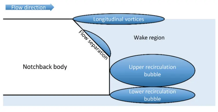
When the air moving over the vehicle is separated at the rear end, it leaves a large low pressure turbulent region behind the vehicle which is known as the wake regioon.This contributes to the formation of pressure drag which affects the vehicle performance.
When the vehicle is moving at a certain velocity the fluid imparts viscous force to the vehicle as long as it is in the viscous sublayer of the boundary.When the fluid reaches the rear end of the vehicle it gets detached from the surface of the body causing negative pressure in the wake region.The movement of the fluid around the vehicles depends on the geometry of the car and the reynolds number.
SIGNIFICANCE OF POINT OF SEPARATION:
The point of separation will occur when there is a discontinuity in the surface or a region of the negative pressure gradient (a sharp end or rear portion of the car).
When the flow is attached to the body of the vehicle the viscous force will increase which will increase the pressure and decrease the velocity before the rear end of the vehicle. As soon as the air encounters the sharp turn causing the velocity to decrease resulting the negative pressure region which is in the wake region.The recirculation region happens beyond the point of separation.
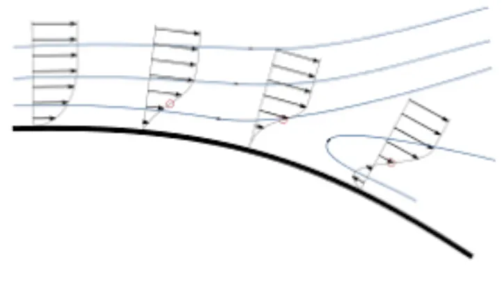
If the rate if change of pressure is large the mixing process will not occure and the boundary layer flow stops.
The above figure shows that at the point of turning the flow gets separated form the boundary layer and there is a region of recirculation after which the flow attaches itself to the boundary layer.
In order to reduce the separation of fluid from the boundary layer,it is advisable to have a smooth edge to reduce the effect of drag on the vehicle.
SIMULATION APPROACH USING k-EPSILON FOR FINER MESH:
1.After the first simulation is run successfully the duplicate of the simulation is created in workbench for a finer mesh and the geometry is loaded in space claim.
2.A local region for refinement is created for Ahmed body using another enclosure for the body.
3.As the body is perfectly symmetric, the simulation is executed by considering the half body.This is the best practice where we can save the number of cells and get the results faster as well.
4.The geomtery is then loaded for meshing.The multizone method is selected for the outer enclosure to provide hexahedral mesh which provides accurate results for the simulation.
5.The element for the first enclosure will vary as 100mm,90mm,80mm teh element size for the second enclosure will vary 50mm,45mm,40mm the element size of leg will be 5mm, the total thickness for the inflation layer for say (no of layers)1.2^(no of layers) with growth 1.2 is used.
6.Steady-state, the density based solver is used.
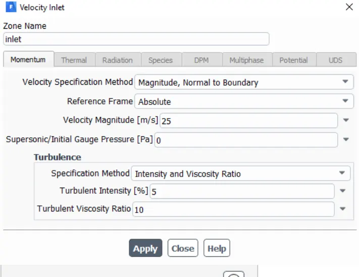
7.Reference values are updated as per the given conditions, for the inlet boundary inlet velocity of 25m/s and 300K temperature are set.
8.Drag coefficient and lift coefficient plot is created by using reference as car walls.
9.Then the simulation is initiated by hyridization with t=0.
10.The cut plane-z is created along xy plane, contour plots for velocity and pressure are created along cut plane z.
13.Animation videos are created for velocity contour.
14.The simulation is executed for 1000 iterations.
GEOMETRY SETUP FOR AHMED BODY:
The geometry of Ahmed body is as shown below
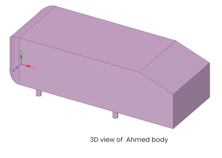
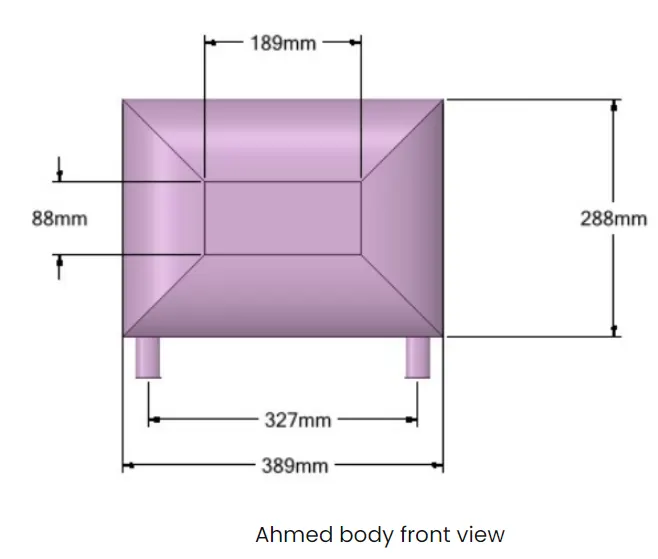
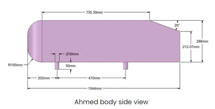
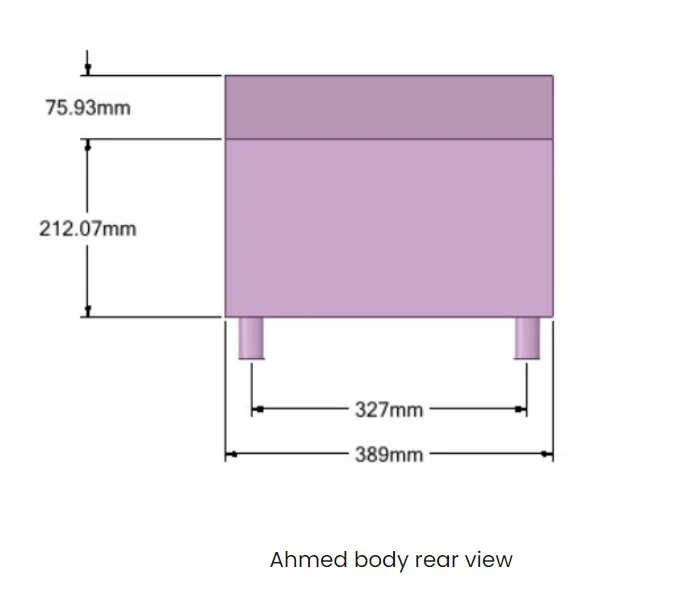
As the body is perfectly symmetric we run the simulation by considering half body.This is the best practice where you can save number of cells and get the results much faster.
First the geometry is loaded in spaceclaim and external enclosure is made as follows with the following dimensions

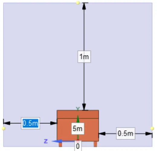
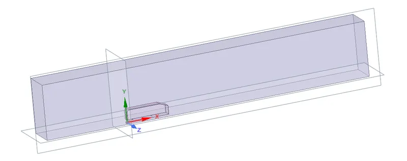
Once the geometry is made then the meshing is done with default settings as follows
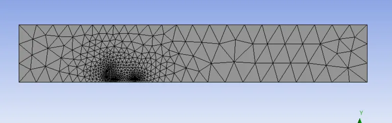
The boundaries are named using named selection for inlet, outlet, and the faces of enclosures and ahmed body as car wall.
Then the simulation is run.
Next for a finer meshing, another closely enclosure is created around ahmed body as follows.
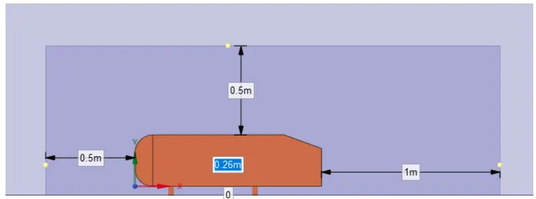
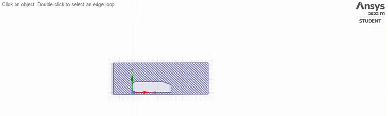
Ahmed body with inner and outer enclosure looks as follows
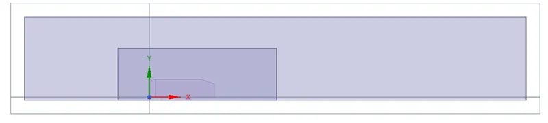
After both the enclosures are created, we check the interference and avoid overlapping of meshing in the 2nd enclosure by applying check interference and deleting the overlap.This function is automatically done by spaceclaim when the interference option is selected inside prepare.
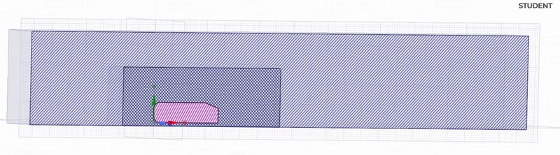
Now there is no interference i.e overlapping of mesh
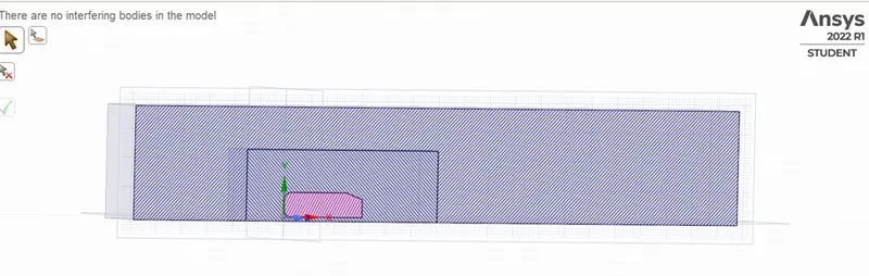
This is the outer enclosure to the car wall
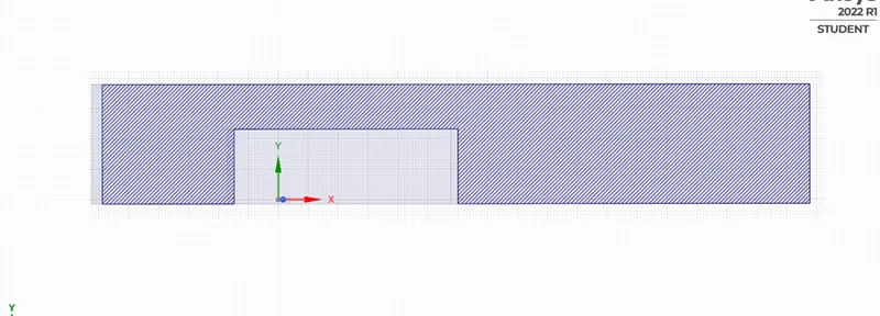
This is the inner enclosure to the car wall
After clearing the interference, we can now split the body into half using the split body command in design, but before that we need to generate planes along x,y,z axes.Then hide the unnecessary planes and use the XY plane.Choose the split bode and choose enclosure needed to split, select the plane and part needed to be removed.Similary do for another enclosure and the body and we get as follows
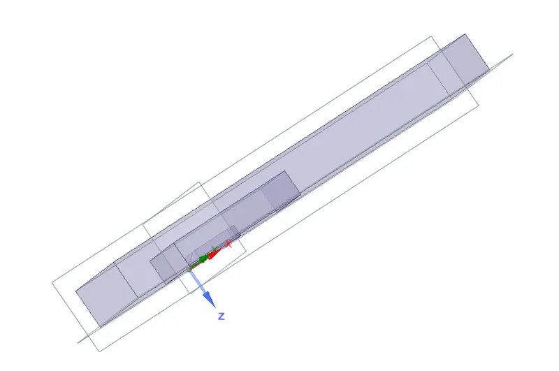
After achieving the split, hide the ahmed body, suppress the physics and go to properties, and select share topology.Now the mesh from the enclosures can share the information and have the symmetry.
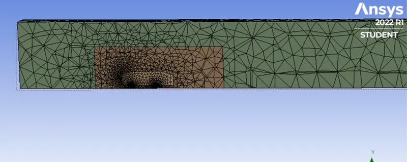
The mesh looks as follows and the mesh is not properly meshed, for it to refine we do meshing with different element size for body i.e outer enclosure(100,90,85mm) and inner body i.e inner enclosure (50,40,35mm) and for the legs of the car 5mm element size.
First the body is selected as shown below
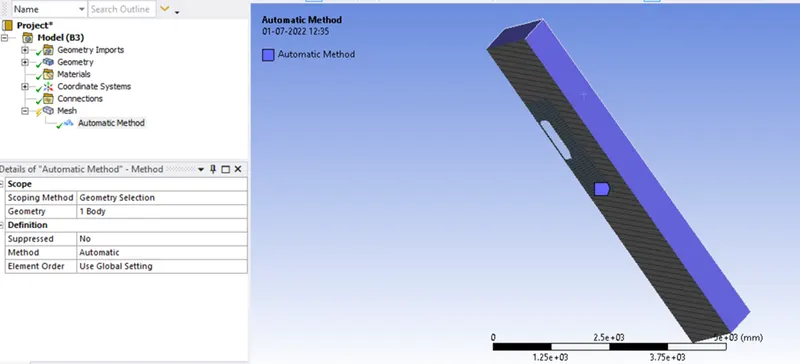
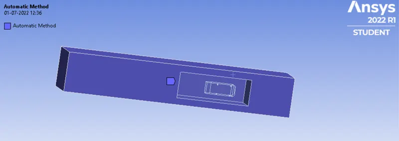
Then a multizone method with hexa mesh is applied
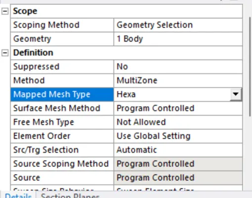
And for the body selected we apply 100mm element size for CASE-I and with change in element size for another two cases similary.
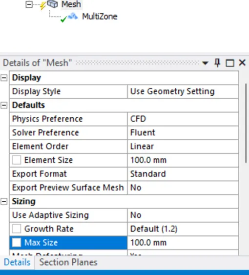
After generating mesh for 100mm element size for outer enclosure it looks as follows and it can be seen that it overlaps in a bettery way with the inner enclosures mesh
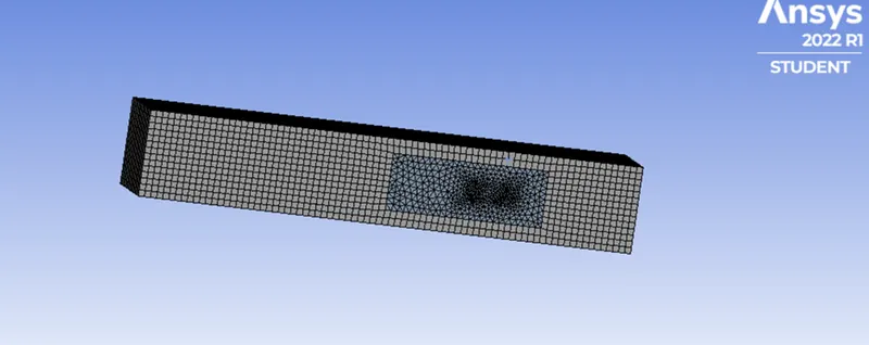
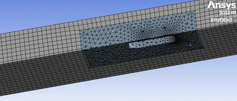
Next for the inner enclosure is selected by deselecting the faces ot the outer enclosure and 50mm element size is used
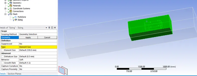
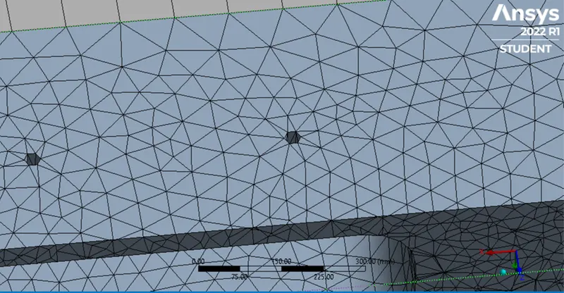
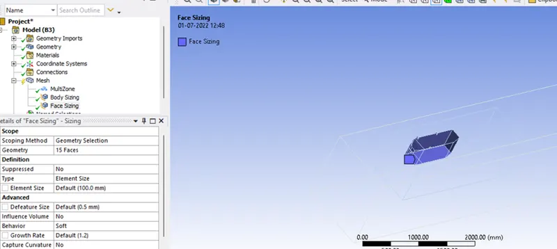
It looks as follows for inner enclosure
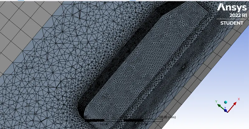
Even though the mesh is good the legs of the Ahmed body aren't completely in circular shape for it to mesh properly we use single face select tool and select the 4 faces and give element size as 5mm
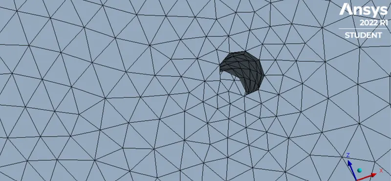
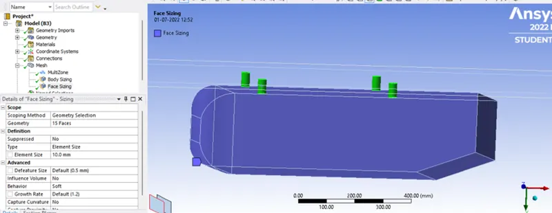
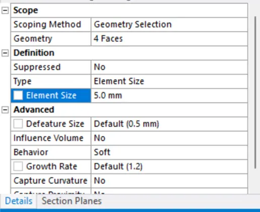
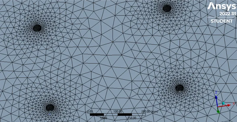
Then after generating the mesh the legs of the Ahmed body are also fixed as can be seen in figure below
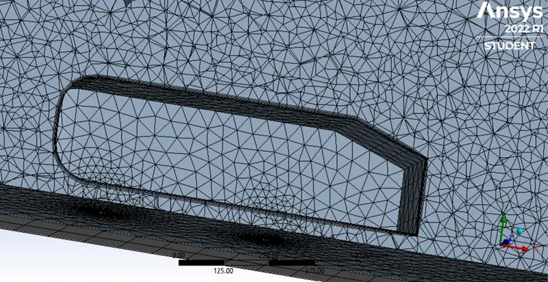
To make the boundary walls ideal an inflation layers are added
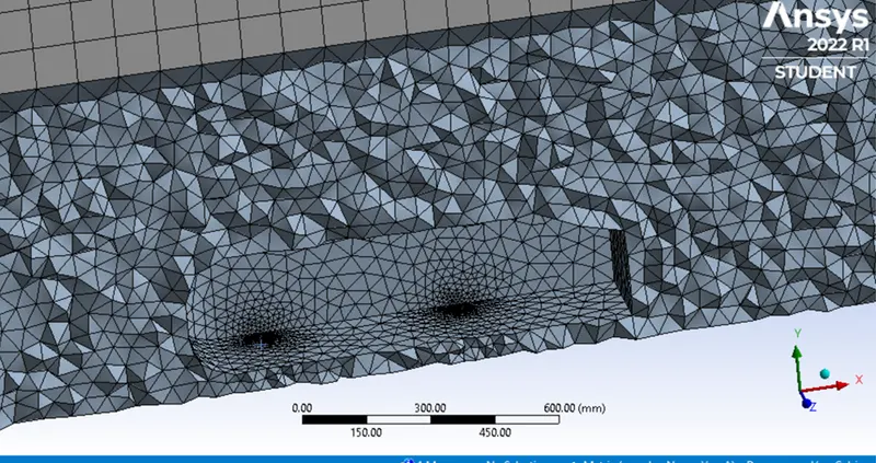
The size of inflation layer is for first layer 5mm with growth 1.2 and total thickness 12.44
CASE-I: SIMULATION FOR AHMED BODY BY k-EPSILON
Outer enlosure element size 100mm
Inner enclosure element size 50mm
Face sizing legs elemental size 5mm
Inflation for ahmed body with 5 layers 1.2 growth total thickness 12.44mm
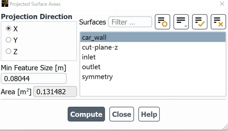
The area of the Ahmed body is as follows for the car wall
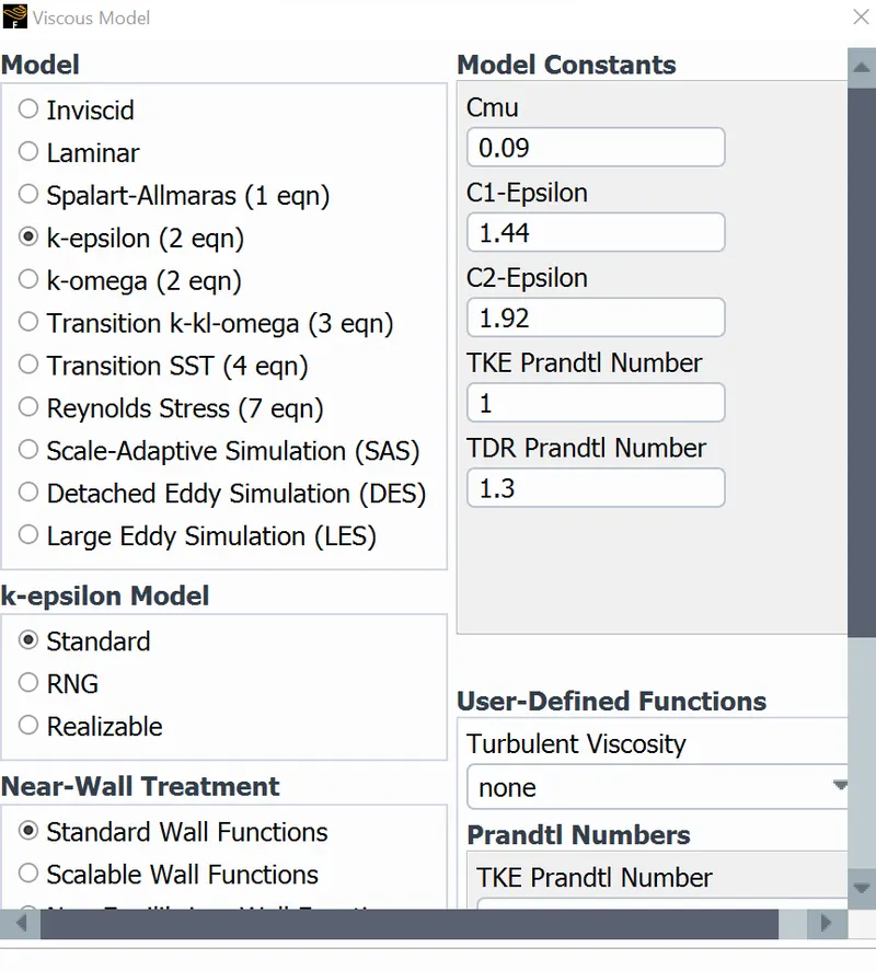
Velocity of 25m/s is defined
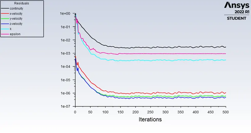
The residual plots are
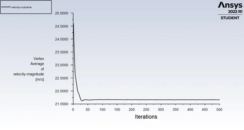
The velocity plot is
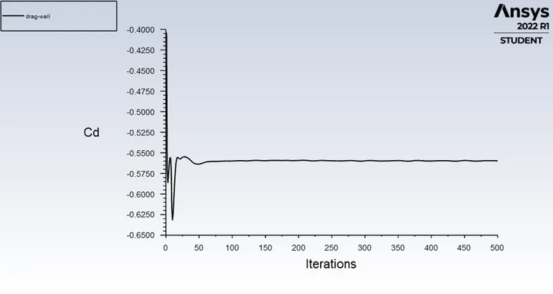
The coefficient of drag is -0.5597849
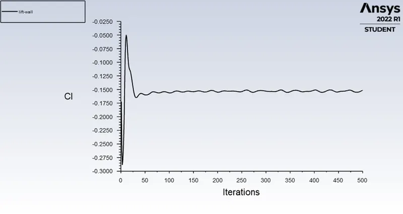
The lift coefficient is -0.151439
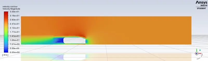
The velocity contour is
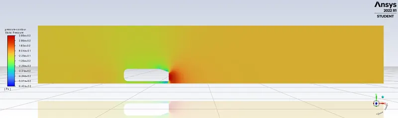
The pressure contour is
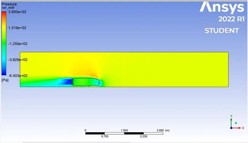
The pressure on car wall can be seen below by adding the cut plane in xy plane we see that the pressure is more at the front and less at rear
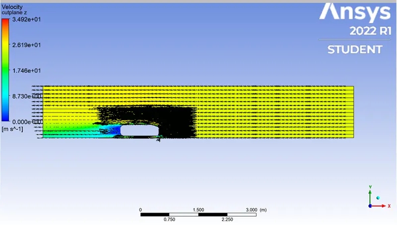
The vectors are as follows
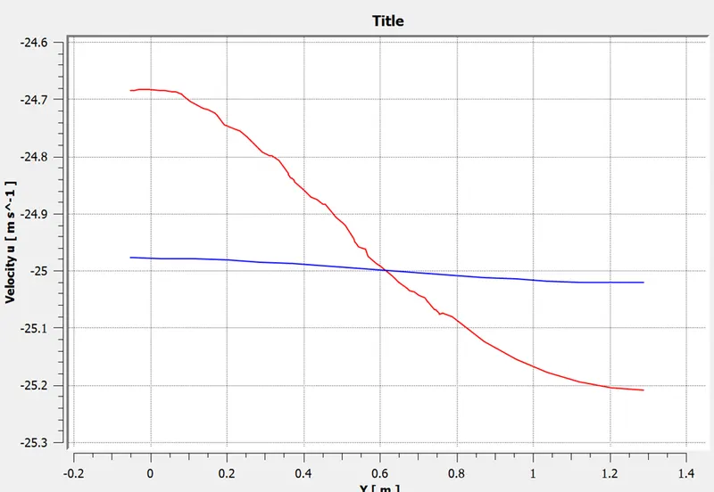
The velocity on x-axis at a distance of 2m(line1) and 3m(line2) from the rear end where the velocity of fluid is as shown below
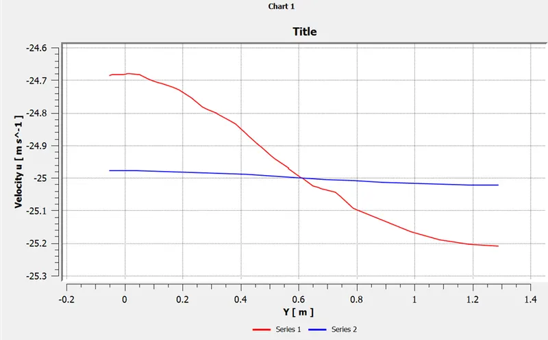
CASE-II: SIMULATION FOR AHMED BODY BY k-EPSILON
Outer enlosure element size 90mm
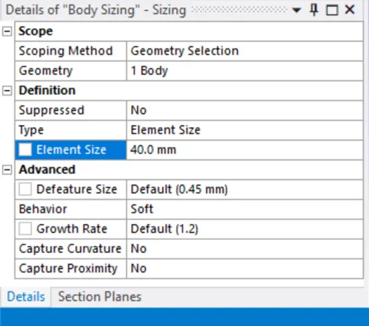
Inner enclosure element size 40mm
Face sizing legs elemental size 5mm
Inflation for ahmed body with 5 layers 1.2 growth total thickness 12.44mm
The mesh size for body is changed to 90mm
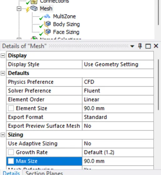
For inner enclosure body changed to 40mm
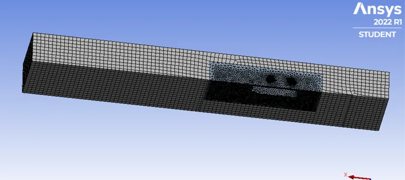
The mesh is now changed as shown below
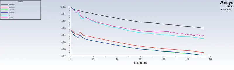
The residual plots are
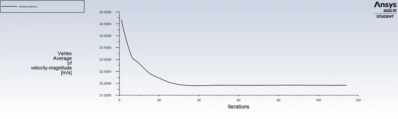
The velocity plots are
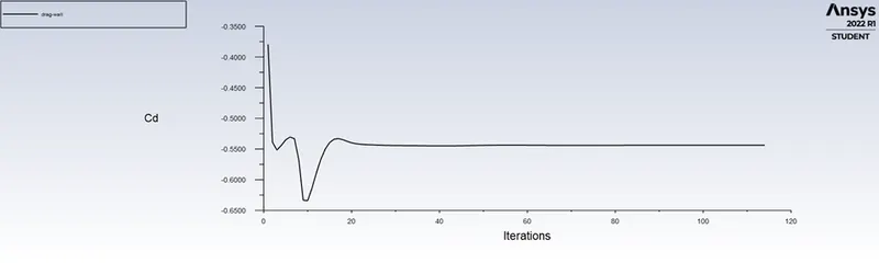
The coefficient of drag is -0.19710145
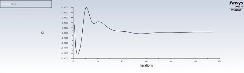
The coefficient of lift is -0.54374526
The velocity contour is
The pressure contour is
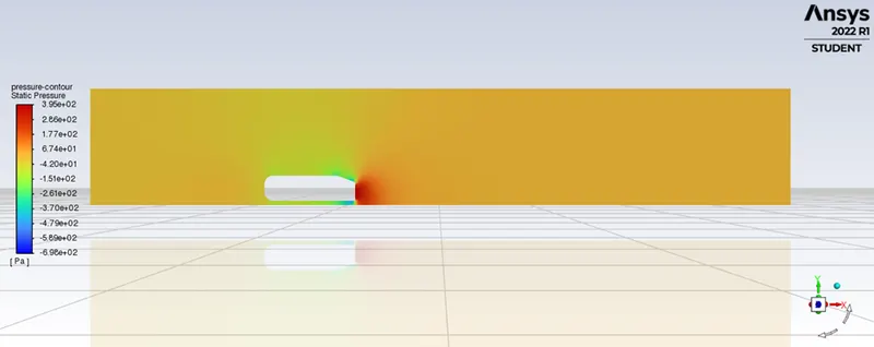
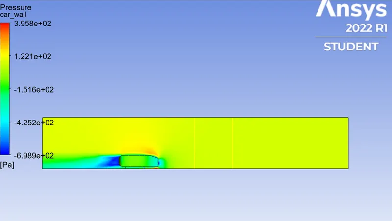
The pressure on car wall can be seen below by adding the cut plane in xy plane we see that the pressure is more at the front and less at rear
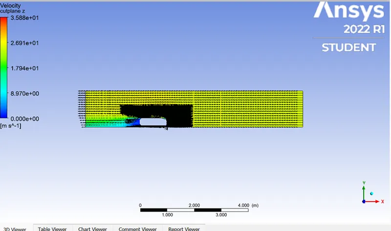
The velocity vectors are
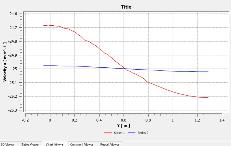
The velocity on x-axis at a distance of 2m(line1) and 3m(line2) from the rear end where the velocity of fluid is as shown below
CASE-III: SIMULATION FOR AHMED BODY BY k-EPSILON
Outer enlosure element size 85mm
Inner enclosure element size 35mm
Face sizing legs elemental size 5mm
Inflation for ahmed body with 5 layers 1.2 growth total thickness 12.44mm
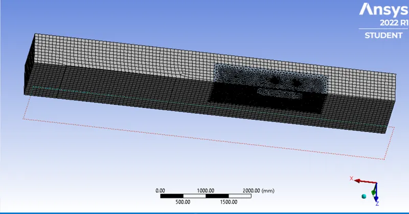
The mesh size for body is changed to 85mm and for inner body to 35mm and it looks as below
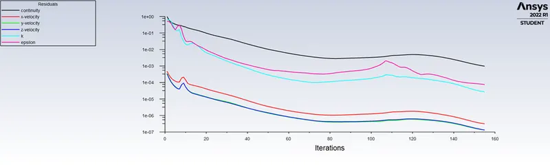
The residuals are
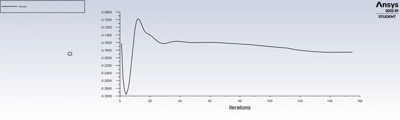
The coefficient of lift is -0.18513654
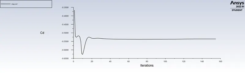
The coefficient of drag is -0.5357061
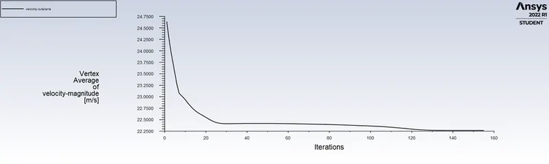
The velocity is
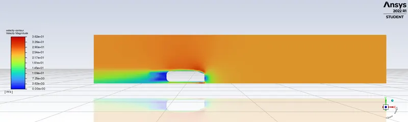
The velocity contour is
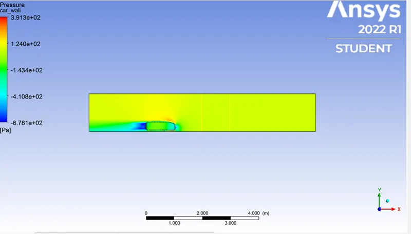
The pressure on the car wall is as follows
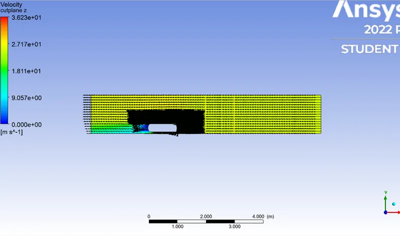
The vector vellocities are as follows
The velocity on x-axis at a distance of 2m(line1) and 3m(line2) from the rear end where the velocity of fluid is as shown below
RESULTS:
| NO OF CELLS | Cd | Cl | |
| CASE-I | 175635 | -0.5597849 | -0.151439 |
| CASE-II | 283985 | -0.19710145 | -0.54374526 |
| CASE-III | 383049 | -0.5357061 | -0.18513654 |
From the above table with the refinement of the mesh, Cd approaches closer to the analytical values that is because more cells are assigned at the boundary layer which results in more accurate results of drag coefficients.
CONCLUSION:
Higher pressure is formed at the frontal area of the Ahmed body due to the loss of kinetic energy of the air.The adverse pressure gradient is created near the wake regions because of the flow separation which is occuring because of the geometry of the model.As a result flow separation alters the pressure gradient which in turn affects the drag and lift coefficients.
In order to reduce the size of the wake region, detachment of the fluid should be farther away from the body which can be achieved by an increase in the slant angle.
With increase in mesh size, the numerical results approach closer to the experimental results.