Week 3 - External flow simulation over an Ahmed body.
REPORT Week 3 – External flow simulation over an Ahmed body
AIM
To simulate the velocity of 25 m/s with the default air properties in Ansys Fluent.
EXPLANATION
Ahmed Body
The first Ahmed body was created by S.R.Ahmed in his research ‘Some salient features of the time-averaged ground vehicles wake’ in 1984. Since then, it has become a benchmark for aerodynamic simulation tools.
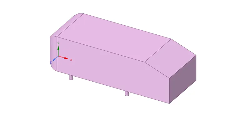
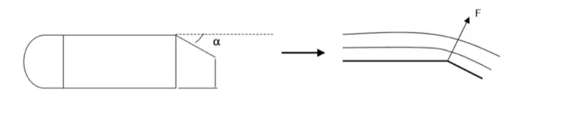
Ahmed body represents simplified vehicle geometry of a bluff body type. The simple geometrical shape has a length of 1.044 m, a height of 0.288 m, and a width of 0.389 m. It also has 0.5 m cylindrical legs attached to the bottom of the body and the rear surface has a slant that falls off at 40 degrees.
The flow around the vehicle is characterised by high turbulent and three-dimensional flow separations, and there is a growing need for more insight into the physical features of these dynamical flows. The principal objective to study such a simplified car body is to tackle the flow processes involved in drag production. Through perceiving the mechanisms involved in creating drag one can be able to design a car to minimize drag and therefore reduce fuel consumption and maximize vehicle performance.
Importance: Its shape is simple enough for accurate flow simulation and retains some important practical features relevant to the automobile's body. This model helps us to calculate the turbulent flow field around the simple car using the k-epsilon model.
A typical property of the generated mesh is the y+ value, which is defined as the non-dimensional distance to the wall.
Full resolution in the near-wall region: the first cell lies at most at the boundary of the laminar sub-layer and no further. Here, the y+ value is 1 or below.
Use of wall functions to resolve the near-wall region: There is no need to place cells very close to the laminar sub-layer, typically `30<= y+ <= 300`.
Simulation Process
- SpaceClaim
The Ahmed body geometry is loaded in the Space Claim setup. As the simulation is considered around the body, the geometry is enclosed to simulate the flow around the Ahmed body. To further fine mesh near the body, another enclosure is used near the body. To avoid the overlapping of meshing of the bigger enclose box with the smaller one, an interference check tool is used to determine as well as eliminate the issue. Also, enable share topology between intersecting bodies.
- PrePost
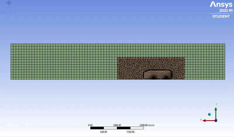
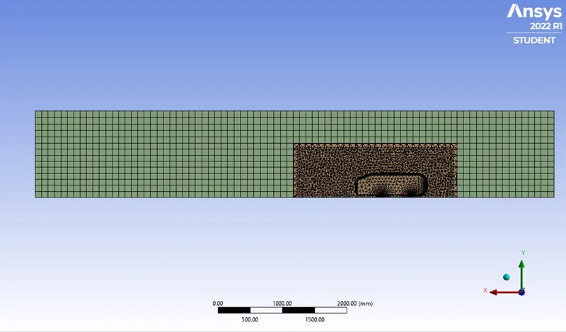
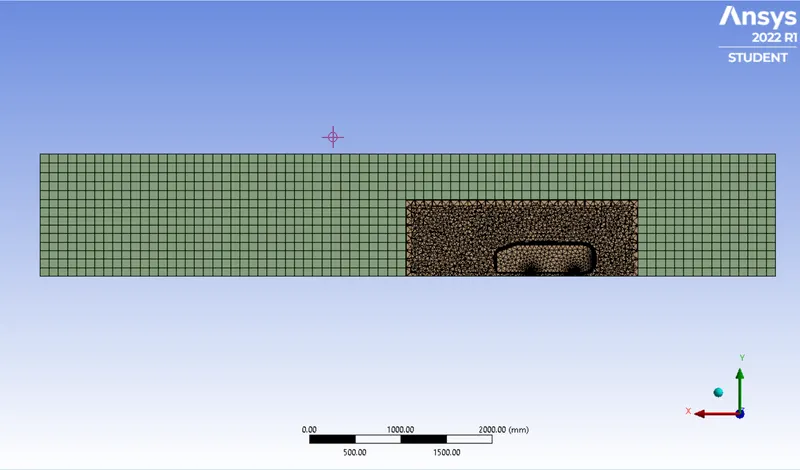
Generate mesh. A multizone method is used to distinguish between two domains and concentrate on the interior domain where the air is going to flow over Ahmed body. The MultiZone method is used with Hexa mapped mesh type.
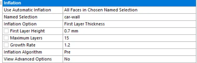
Apply the MultiZone method over the exterior enclosure. Apply body sizing over the interior enclosure with an element size of 50 mm. Face sizing is applied over Ahmed body with an element size of 5 mm. Provide name selection to the geometry to ease the boundary condition selection. In details of mesh, apply inflation layer on the car wall with inflation option of first layer thickness providing maximum thickness appropriately according to the desired y+ value ( considered value 50). Maintaining the y+ in the appropriate range will give the correct value for the drag coefficient.
- Ansys Fluent ( pre-processing and solver setting )
The next step in the simulation after generating the meshing is to set the physical properties for the case. First, check mesh Quality.
Solver
- Type – Pressure-based
- Velocity Formulation – Absolute
- Time – Steady
Viscous
- Turbulence
- k-epsilon (2 equation)
- Model – Standard
- Near-Wall Treatment – Standard Wall Functions
- Material – Air
Density - 1.225 kg/m3
- Boundary
- Inlet
- Velocity magnitude = 25 m/s
- Symmetry-wall
- Symmetry boundary condition
- Inlet
- Outlet
- Gauge pressure – zero Pa
Solving
- Initialization using hybrid
- Calculating with 500 iterations
- CFD Post
After setting up the case and providing appropriate initial and boundary conditions, several simulations are performed on Ahmed body, mainly for comparing results from different mesh sizing.
RESULT
CASE 1
Statistics

Mesh
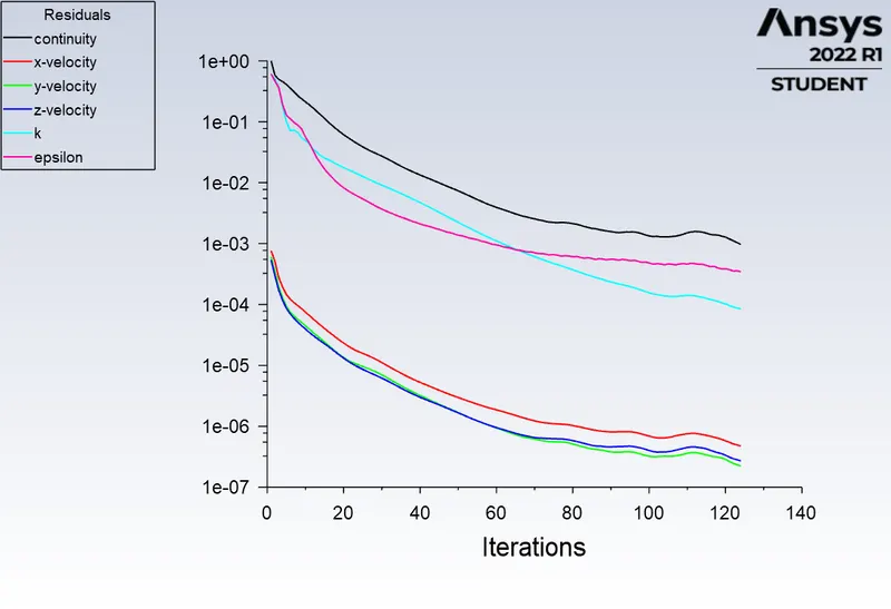
Residual plot
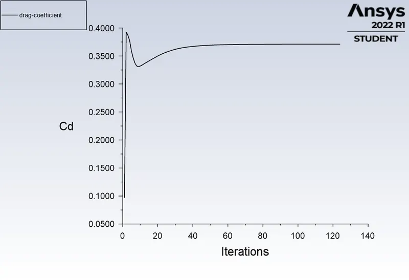
Coefficient of drag plot
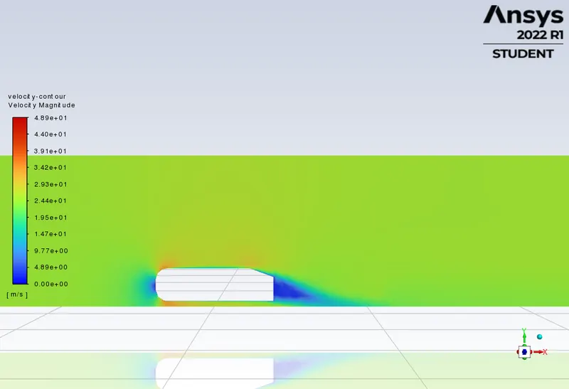
Velocity distribution Contour
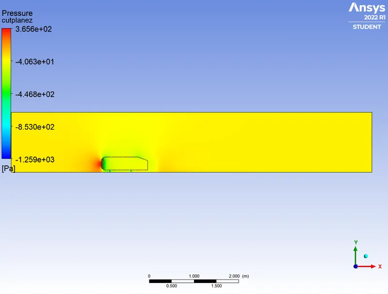
Pressure plot on Ahmed body
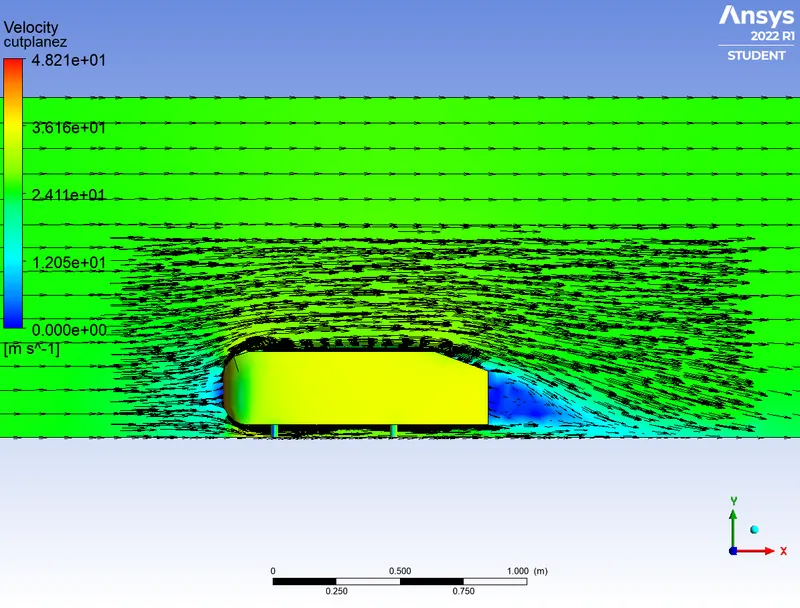
Vector plot of velocity
Value of drag coefficient = 0.3712
CASE 2
Statistics

Mesh
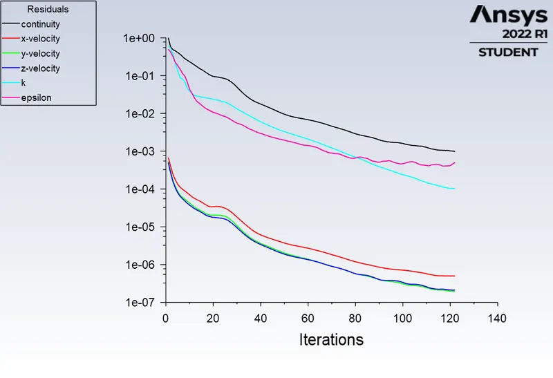
Residual plot
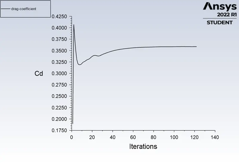
Coefficient of drag plot
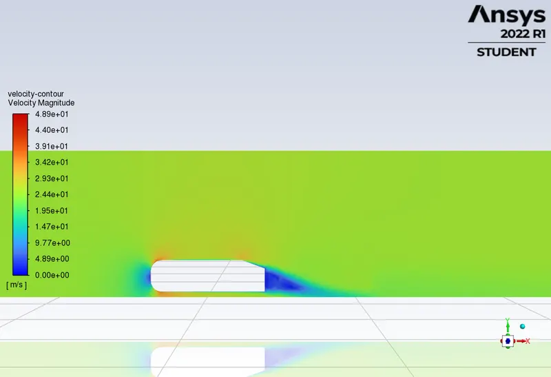
Velocity distribution Contour
Pressure plot on Ahmed body
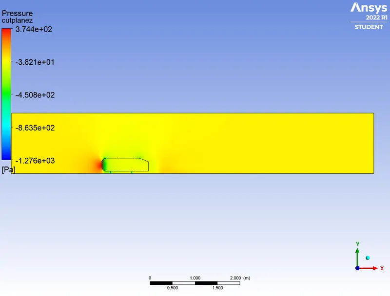
Vector plot of velocity
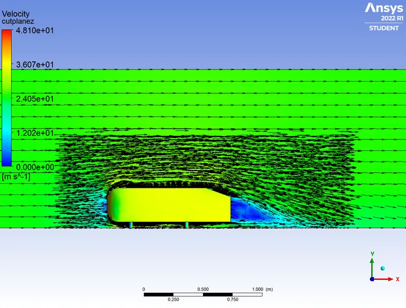
Value of drag coefficient = 0.3585
CASE 3
Statistics

Mesh
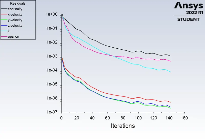
Residual plot
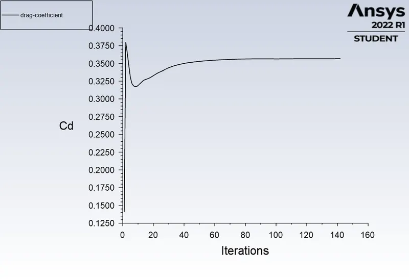
Coefficient of drag plot
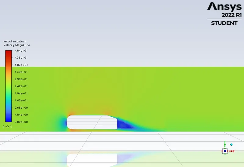
Velocity distribution Contour
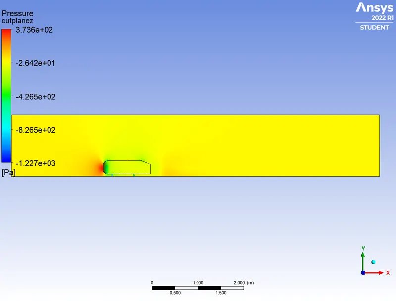
Pressure plot on Ahmed body
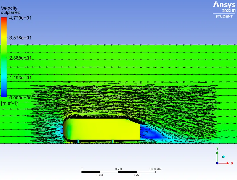
Vector plot of velocity
Value of drag coefficient = 0.3567
OBSERVATIONS
The simulation with only half body will be considered as the body is perfectly symmetric. This is the best method as we can save the number of cells and stimulate the result faster.
Three main features were seen in the model
- The recirculation region is formed as the flow separates at the top of the vertical back surface of the model.
- The recirculation region is formed due to the separation at the base of the model.
- The pillar vortices that form as the vortices in the side boundary layers roll up over the slant edges.
The reason behind the negative pressure in the wake region
- The Law of conservation of energy can be a significant reason behind the negative pressure.
- Flow separation takes place when the fluid hits the Ahmed body, which leads to the formation of air bubbles which are at very low pressure.
- The negative pressure is due to the velocity difference between the infinity velocity and the low Reynolds number at the rear angle.
- The difference leads to the formation of wake, which further increases the drag due to which pressure drops behind the Ahmed body.
- Pressure could also become negative to overcome the shear stress.
Significance of Point of Separation
Flow separation occurs when the fluid boundary layer encounters an adverse pressure gradient. The point on the body where the boundary layer lifts off the surface is called the separation point. Many factors like flow direction, lift on the body, and drag due to the ‘tip vortex’ depends on the alpha angle.
To have better performance of an Automobile or any vehicle this separation needs to be avoided or delayed, for smooth flow over the surface of the vehicle.
CONCLUSION
- The grid dependency test allows seeing the smoother velocity profile, as the mesh is made finer i.e. when the cell count is increased. This can be noticed from the vector plots of the velocity, as the results become more accurate.
- The finer mesh depicts the more clear formation of the wake region.
REFERENCES