Week 3 - External flow simulation over an Ahmed body.
OBJECTIVE: External flow simulation over an Ahmed body.
PROCEDURE:
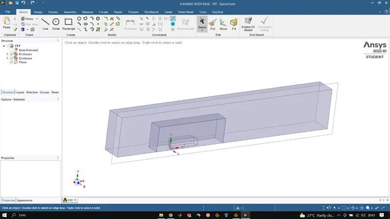
We initiate by importing the AHMED BODY CAD file into space claim which we opened in ANSYS workbench, Once the model loaded, we used the enclosure tool to create geometric enclosures over the body to capture the flow volume, to bring in more accuracy without exceeding our element count limit of 512k we created a smaller enclosure in the main enclosure so that it could be more refined, size of the smaller enclosure was determined by the wake region size of base model. The main enclosure size is mainly the wind tunnel size dependent for real life data simulations. We used the cut section view to check for interference in the geometry and removed it using the interference tool and also wee enabled the share topology setting for the whole geometry so that the mesh is well defined and accurate as well as continued. We used the split body tool to divide the model into half as it is symmetric so the results on one side will be same as the other side and hence we used the split body so that we could refine the mesh more and without exceeding the element limit. Once all this was done space-claim was closed.
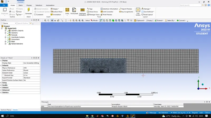
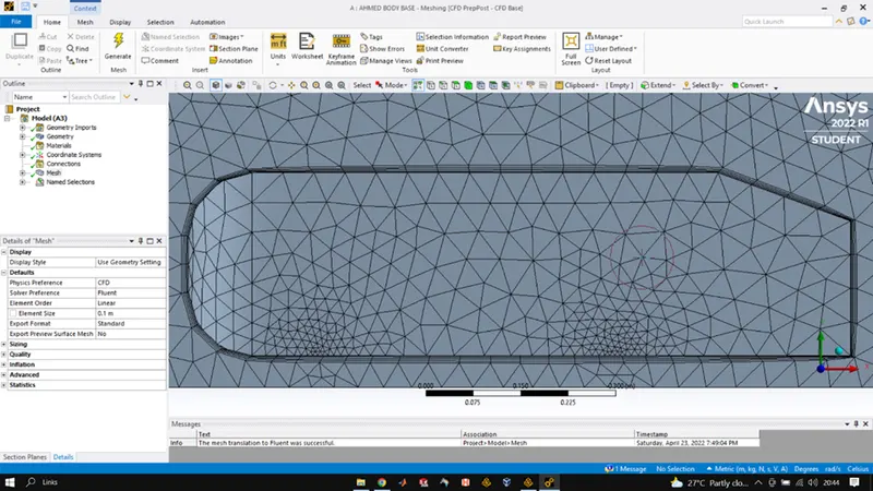
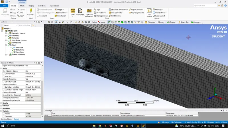
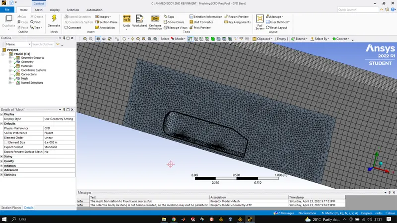
After completing the setup in space claim we launch Ansys mesher here we firstly name our boundaries as it is important to do this step at the very beginning. After that we generated the mesh so as to have idea where we need more refinement and do the same region by region. Once the base meshing was done, we inserted the method to the mesh where the outermost enclosure was selected and the type was selected to multizone it basically creates hexahedral mesh where ever possible and they are actually really good. Then we inserted sizing for the inner enclosure where the size was set to 50mm and mesh was updated. Over all mesh element size was set at 100mm for the main enclosure. After that we again added sizing for the mesh and this time we selected the base blocks of AHMED BODY and the size given ti them was 5mm and at last we inserted an inflation layer which was set to the CAR-WALL and the total thickness criteria was selected with total thickness being 12.44 mm. after this mesh was finally updated and the mesh GUI was closed.
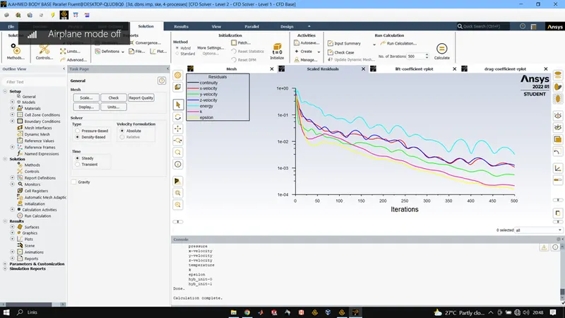
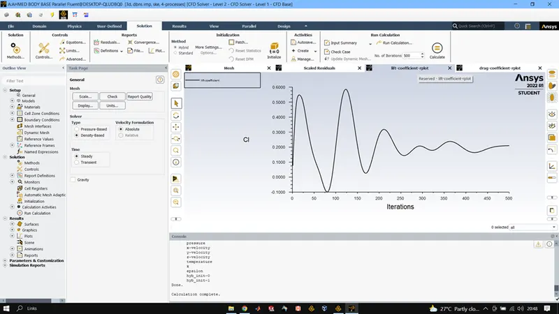
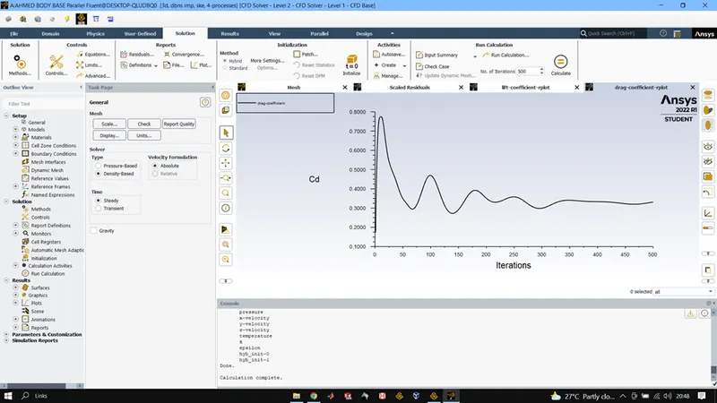
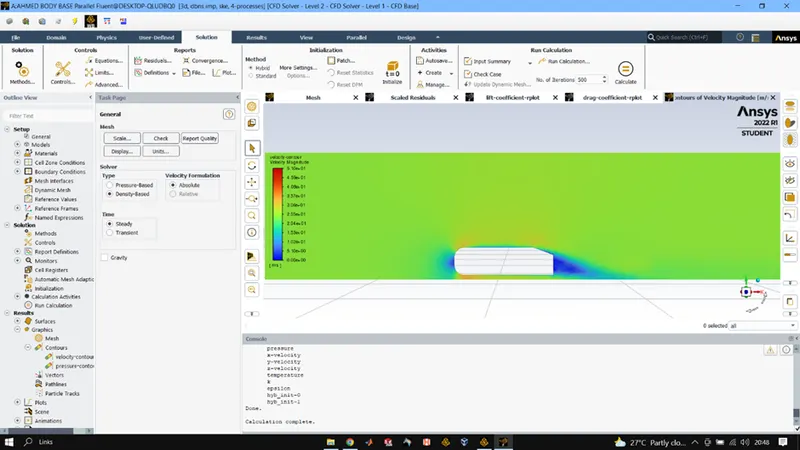
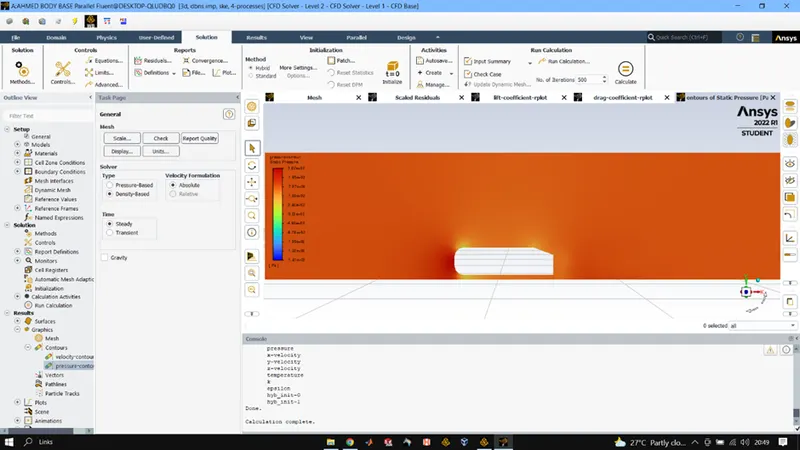
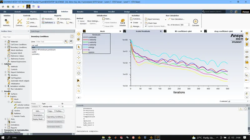
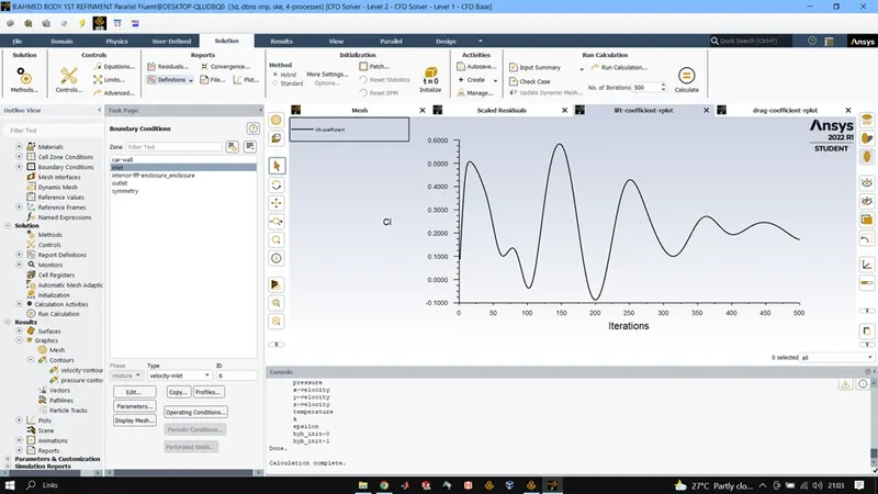
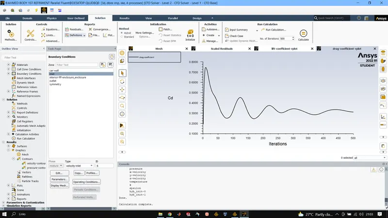
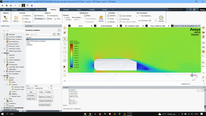
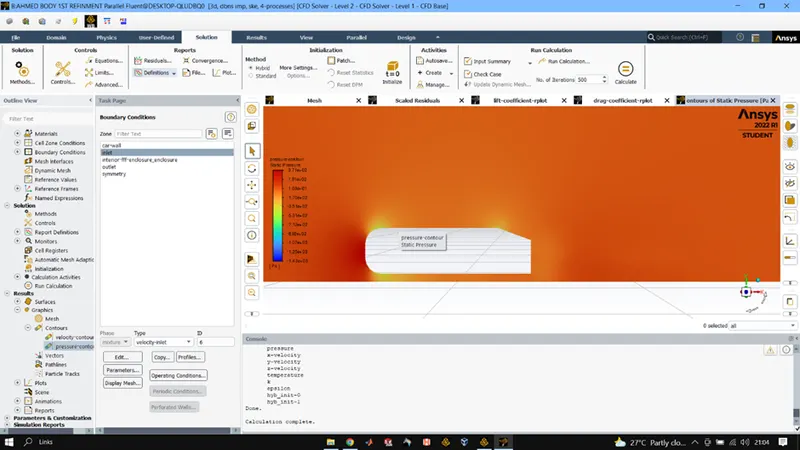
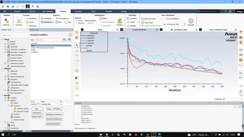
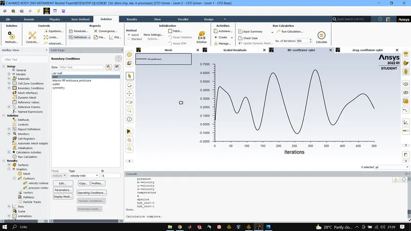
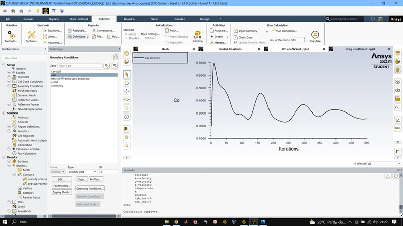
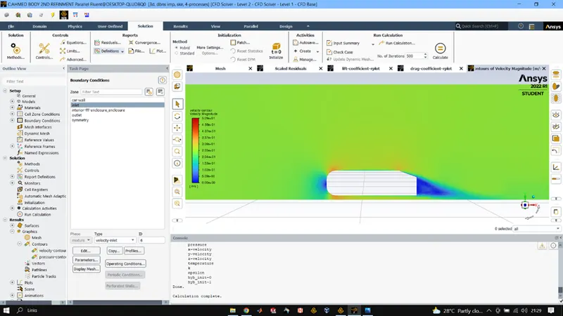
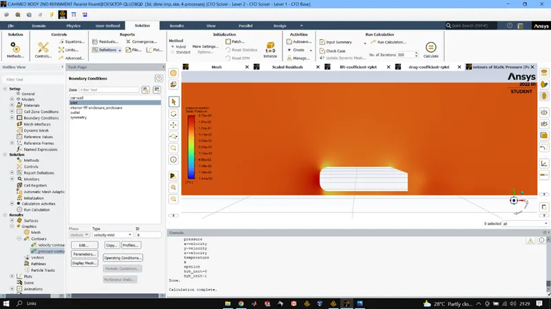
After that we launched ANSYS fluent setup where we checked for mesh once it was ok, we went into physics and then gave 25m/s speed at inlet the viscous model selected was k-epsilon and the energy calculations were checked in. after that we inserted definition to get drag and lift coefficient plots. And then the solution was initialized using the hybrid solver. Once this was done in the results, we created a plane by normal and point option and after that we created contours of velocity and pressure on that plane. And then the solution was run for 500 iterations.
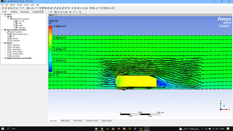
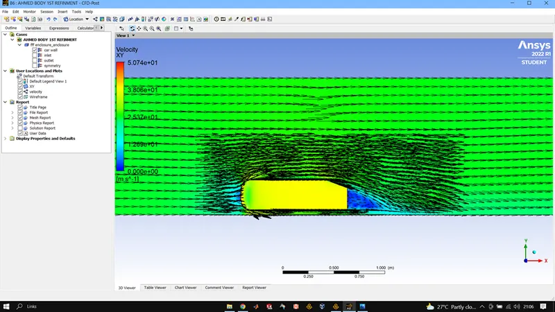
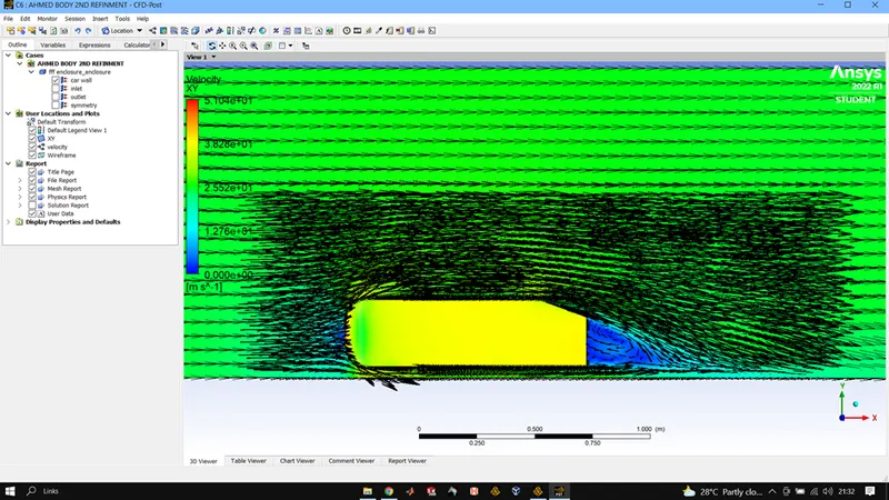
The plots were observed and the contours were analyzed and after that we used post-processing in ANSYS to plot vectors on a XY plane and pressure on the body of car.
RESULTS:
OUTER ENCLOSURE: 100MM
INNER ENCLSOURE: 50MM
AHMED BODY BASE: 5MM
INFLATION LAYER TOTAL THICKNESS: 12.44MM
OUTER ENCLOSURE: 80MM
INNER ENCLSOURE: 40MM
AHMED BODY BASE: 5MM
INFLATION LAYER TOTAL THICKNESS: 12.44MM
OUTER ENCLOSURE: 60MM
INNER ENCLSOURE: 30MM
AHMED BODY BASE: 5MM
INFLATION LAYER TOTAL THICKNESS: 12.44MM
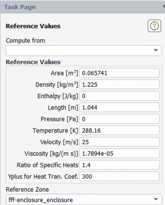
REFERENCE VALUES:
RESULTS:
|
CASE |
CELL COUNT |
Cd |
Cl |
|
BASE LINE |
87641 |
0.33 |
0.24 |
|
1ST REFINMENT |
147596 |
0.31 |
0.18 |
|
2ND REFINMENT |
316955 |
0.245 |
0.18 |
CONCLUSIONS:
Ahmed's body and its importance.
An Ahmed body is a simplified car body used in automotive filed to study the impact of the flow pattern on the drag. External dynamics of the car defined major traits of an automobile, and Ahmed body helps understand the physics defining these traits. It helps to analyse the turbulence and vortices. It helps to get more insight into the physical features of dynamic flows over a car body. As well helps to understand the fundamentals of external flow simulations.
Ahmed body was created by S.R.Ahmed in 1984.
The reason for the negative pressure in the wake region.
From the pressure plot on the car body and vector plot of velocity we observe negative pressure at the rear side of the Ahmed body which is called the wake region and the reason for negative pressure is that the flow behind an object separates from the surface and creates a highly turbulent region behind the object, the pressure inside the wake region remains low as the flow separates and a net pressure force is produced. Due to the production of pressure drag being produced from flow separation, vacuum is created at the rear end of the Ahmed body resulting in negative pressure.
Significance of the point of separation.
Separation point can be described as the point where velocity gradient is zero and so is the pressure gradient in X-direction and from this point we observe the negative pressure. At point of separation the fluid flow starts to separate from the surface of the body and here only the wake region is formed hence point of separation holds a lot of significance and can be understood in detail by plotting velocity gradient pressure gradient graphs .
BY PERFORMING THE GRID DEPENDENCY TEST WEOBSERVED THAT THE OUTPUT CONTOURS GOT FINER AND THE RESULTS GOT MORE ACCURATE WITH THE REAL WORLD ANALSYS RESULTS.