Week 3 - External flow simulation over an Ahmed body.
Introduction:
The Ahmed body is a simplified car body used in the automotive field to study the impact of the flow pattern on drag. The external aerodynamics of the car defines many major traits of an automobile like stability, comfort, and fuel consumption at high speeds. The flow around the vehicle is characterized by high turbulent and three-dimensional flow separations as well as there is a growing need for more insight into the physical features of these dynamical flows. The Ahmed Body is a simplified car, used in the automotive field to investigate the flow analysis and find the wake flow around the body. Ahmed body is made up of a round front part, a moveable z slant plane in the rear of the body to study the detachment phenomena at different angles, and a rectangular box that links the front part and the rear slant plane. The principal objective to study such a simplified car body is to tackle the flow processes involved in drag production. Through perceiving the mechanisms involved in creating drag one can be able to design a car to minimize drag and therefore reduce fuel consumption and maximize vehicle performance. Besides the analysis of the velocity field, the Ahmed Body is also used for drag force and lift force analyses and rolling, pitching, and yawing moments. The slant angle on the back allows studying the separation region and its influence on the velocity profile and forces.
Geometry:
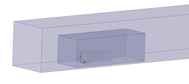
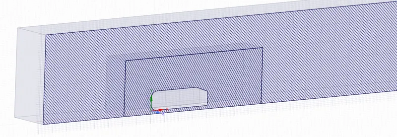
The geometry of the Ahmed body is shown in the figure below. The slant angle is adjustable and is the main variable model parameter in the experimental investigations. The Ahmed body, of length (L) 1044 mm, height (H) 288 mm, and width (W) 389 mm, was placed at 50 mm from the ground (G).
Solver Parameters:
Boundary Conditions:
Inlet: 25 m/s -velocity inlet.
Outlet: Pressure outlet.
Ahmed body: wall.
Rest faces: Symmetry.
Initialization: Standard initialization from the inlet.
Solver: Pressure-based steady-state solver.
Viscous model: K-Epsilon Standard
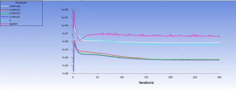
We will be simulating flow around Ahmed body for 3 cases of meshing for grid independence test. Solver parameters are the same for every case with Y+ plus of 30. The number of iterations: 300.
Case-1:
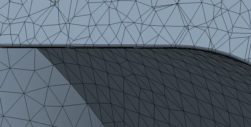
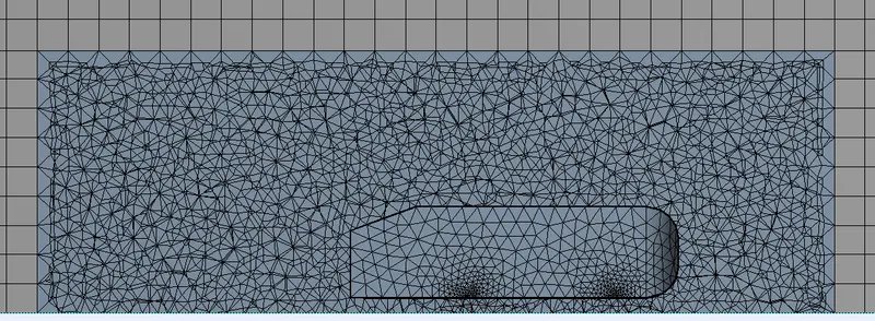
Multizone Meshing: 100 mm, Sizing: 50 mm, Face sizing for Ahmed body supports: 36 divisions with a growth rate of 1.2 and Inflation: 6 layers with a first layer height of 0.429 mm.
Results:
Residuals plot:
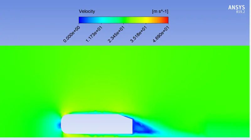
Velocity contour:
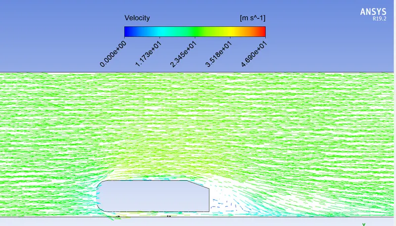
Velocity vector:
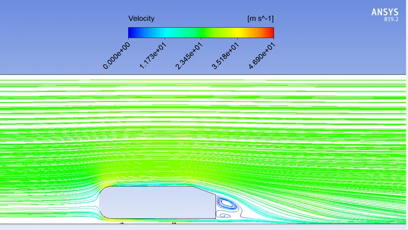
Velocity streamline:
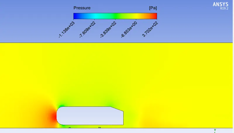
Pressure contour on front face:
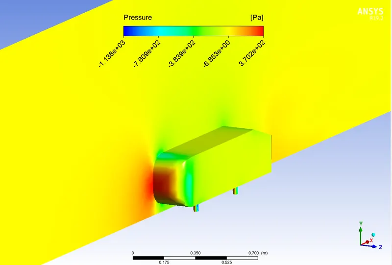
Pressure contour:
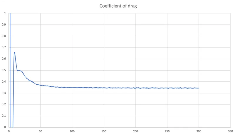
Coefficient of drag:
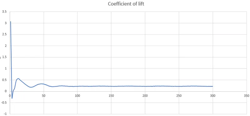
Coefficient of lift:
Case-2:
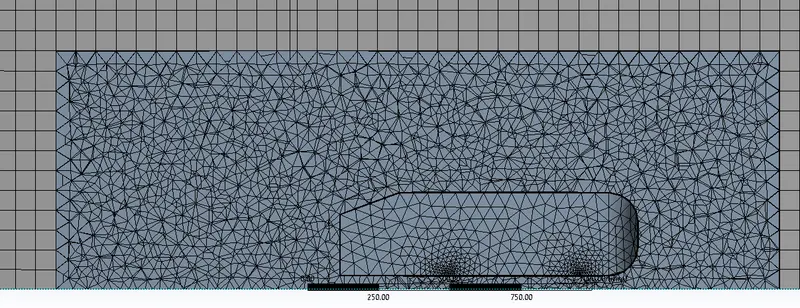
Multizone Meshing: 70 mm, Sizing: 50 mm, Face sizing for Ahmed body supports: 36 divisions with a growth rate of 1.2 and Inflation: 6 layers with a first layer height of 0.429 mm.
Results:
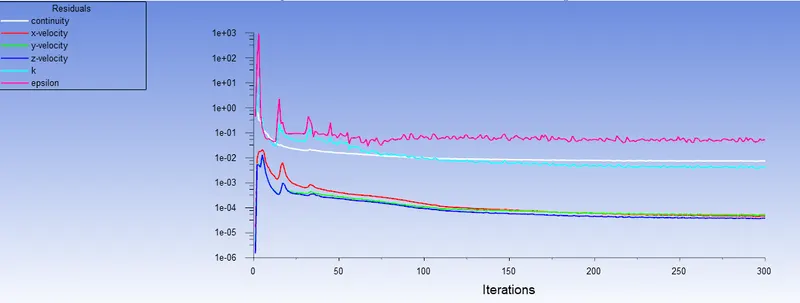
Residuals plot:
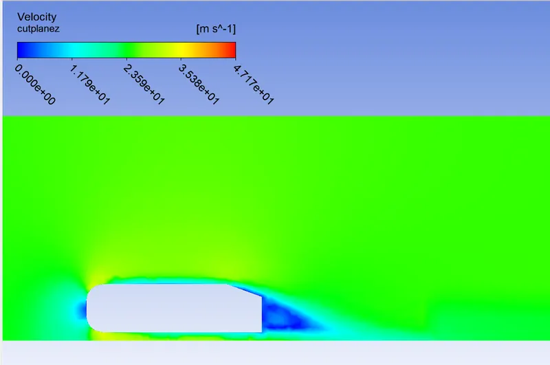
Velocity contour:
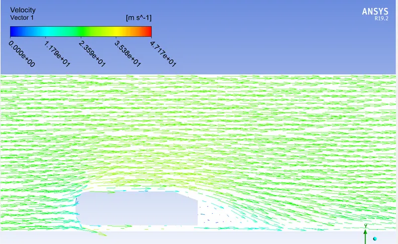
Velocity vector:
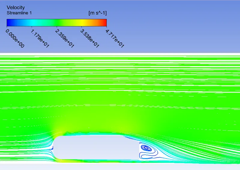
Velocity streamlines:
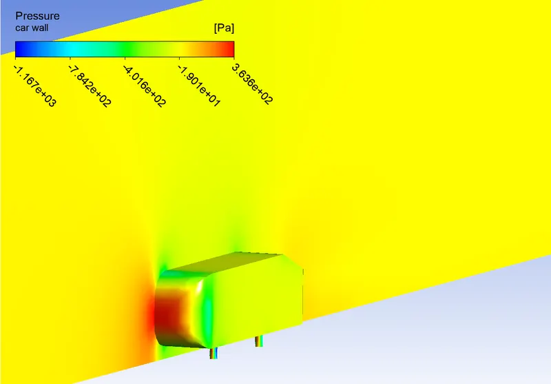
Pressure contour front face:
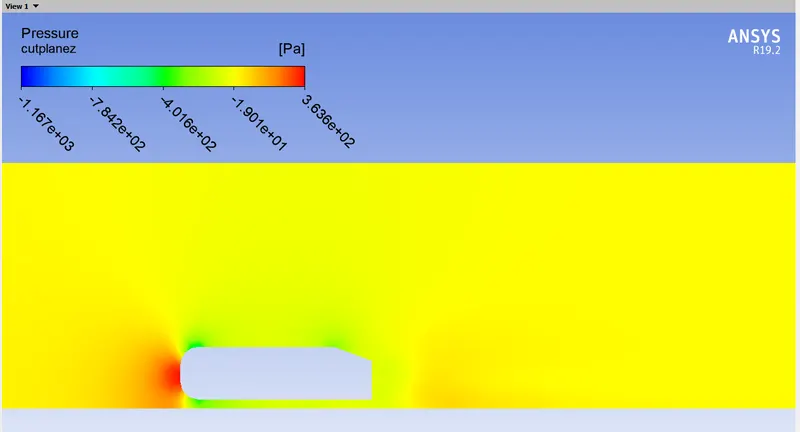
Pressure contour:
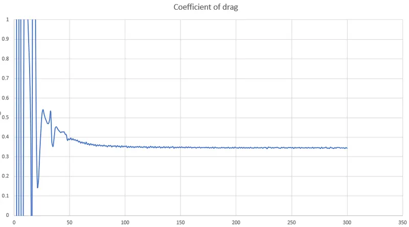
Coefficient of drag:
Coefficient of lift:
Case-3:
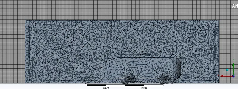
Multizone Meshing: 50 mm, Sizing: 50 mm, Face sizing for Ahmed body supports: 36 divisions with a growth rate of 1.2 and Inflation: 6 layers with a first layer height of 0.429 mm.
Results:
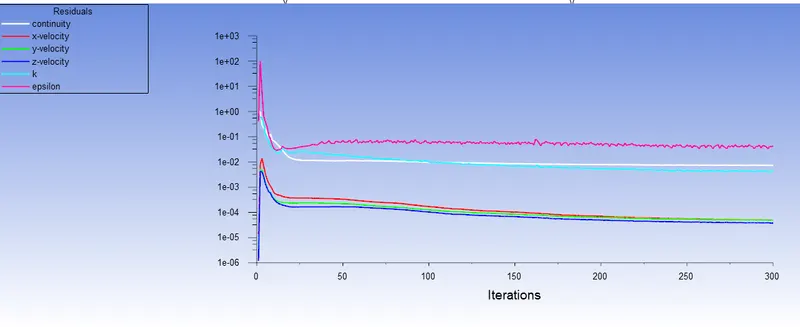
Residuals plot:
Velocity contour:
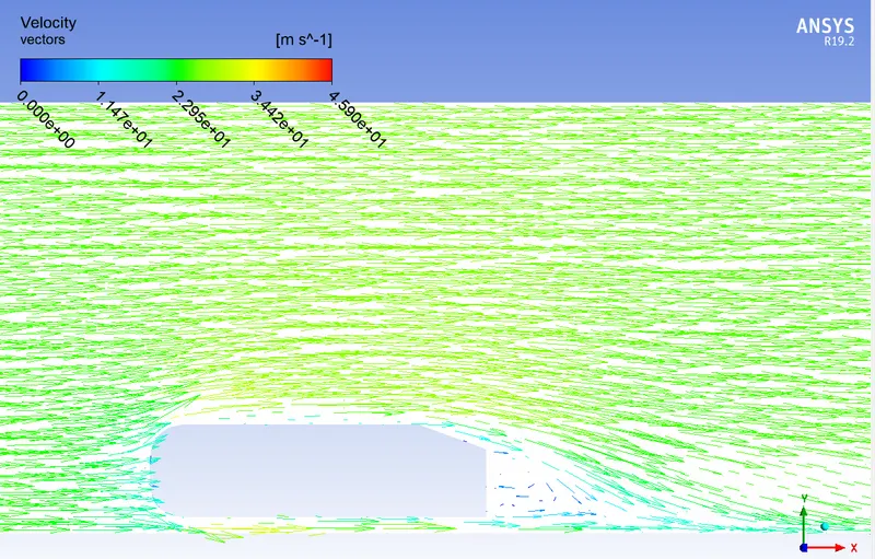
Velocity vector:
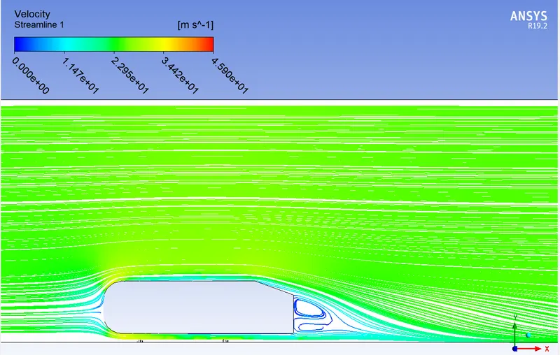
Velocity streamlines:
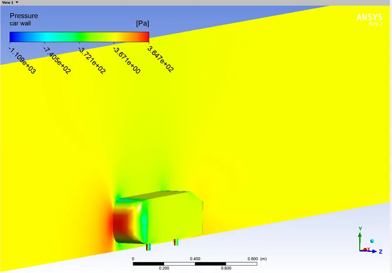
Pressure contour on front face:
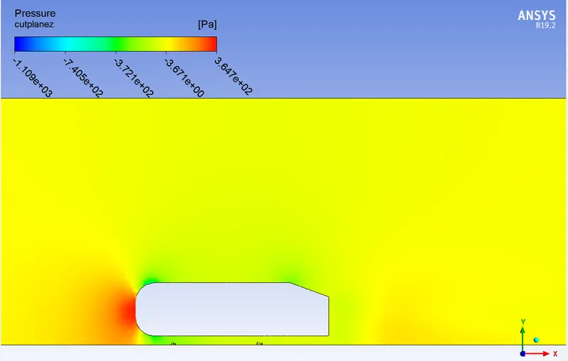
Pressure contour:
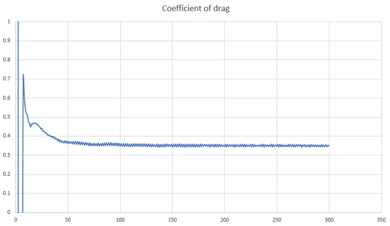
Coefficient of drag:
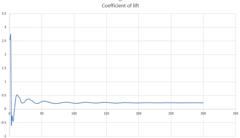
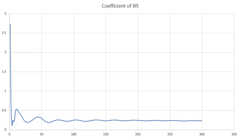
Coefficient of lift:
Grid Independence test:
| Coefficient of drag | Coefficient of lift | |
| Case-1 | 0.341 | 0.213 |
| Case-2 | 0.343 | 0.229 |
| Case-3 | 0.345 | 0.231 |
Negative pressure in Wake Region
When the air moving over the vehicle is separated at the rear end, it leaves a large low-pressure turbulent region behind the vehicle known as the wake. This wake contributes to the formation of pressure drag, which eventually reduces the vehicle performance. The region of recirculating flow immediately behind a moving or stationary blunt body, caused by viscosity, which may be accompanied by flow separation and turbulence flow, or the wave pattern on the water surface downstream of an object in a flow, or produced by a moving object (e.g. a ship), caused by density differences of the fluids above and below the free surface and gravity.
When the vehicle is moving at a certain velocity, the viscous effects in the fluid are restricted to a thin layer called the boundary layer. Outside the boundary layer is the inviscid flow. This fluid flow imposes pressure force on the boundary layer. When the air reaches the rear part of the vehicle, the fluid gets detached. Within the boundary layer, the movement of the fluid is totally governed by the viscous effects of the fluid. The Reynolds number is dependent on the characteristic length of the vehicle, the kinematic viscosity, and the speed of the vehicle. The fluid moving around the vehicle is dependent on the shape of the vehicle and the Reynolds number. There is another important phenomenon, which affects the flow of the car and the performance of the vehicle. This phenomenon is commonly known as the 'Wake' of the vehicle. When the air moving over the vehicle is separated at the rear end, it leaves a large low-pressure turbulent region behind the vehicle known as the wake. This wake contributes to the formation of pressure drag, which eventually reduces the vehicle performance.
Significance of the Point of Separation:
Separation of flow is said to occur when the direction of the flow velocity near the surface is opposed to the direction of the free stream velocity, which means (du/dy) s 0. Such a situation arises when there is a negative pressure gradient near the wall. An example is a subsonic diffuser or rear portion of the car. In the direction of flow the pressure increases which causes decreases in velocity and creates conditions for separation to occur. It is important to note that, the skin-friction coefficient reaches the value zero. At this point, the wall shear stress vanishes is called the separation point. Reverse flow takes place beyond the point of separation. Due to reverse flow, irregular eddies are formed and a lot of energy is dissipated. This region is called Wake. The pressure distribution in the wake is quite different from that on the remaining boundary and this gives rise to an additional drag force on the body Wake also leads to lateral vibration to the object which may be harmful. Also, a large amount of K.E. is lost.
In the turbulent boundary layer, some of the energy is dissipated in friction slowing airflow velocity, resulting in a pressure increase. If the increase in pressure is gradual, the process of turbulent mixing will cause a transfer of energy from the fast-moving eddies to slower ones in the turbulent boundary layer. If the rate of change in pressure is too great for example in sharp comers, the mixing process will be too slow to push the slower air molecules moving. When this happens, the boundary layer flow stops following the contours of the surface, resulting in separation. Air particles downstream of the separation region will then move towards the lower pressure region in the reverse direction to the main flow. The separation region will reattach. In the region between separation and reattachment points, airflow is circulating and this is called the separation bubble. The separation will normally occur if the resultant flow encounters a sharp edge and that is why it is always important for ground vehicles to have smoothly rounded edges everywhere.
CONCLUSION:
Overall conclusion
1. Grid dependency test is important to make the mesh from coarse to fine so that we can get a good result. Y+wall function is very important to get the correct result of coefficient drag & lift.
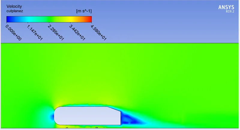
2. Negative pressure in the wake region due to the boundary layer separation, vacuum region is generated & in that region there is the presence of negative pressure and also due to recirculation zone.
3. Boundary layer separation causes and its importance include, In the direction of flow the pressure increases which causes decreases in velocity and creates the condition for separation to occur. It is important to note that, the skin-friction coefficient reaches the value zero. At this point, the wall shear stress vanishes is called the separation point. If the boundary layer is separated out, it affects on the coefficient of drag & lift results.
By having simulated several steady-state simulations, performing a mesh dependency with three cases on an Ahmed geometry, obtaining for each one of them their own significant convergence according to the velocity, drag, and lift coefficients to quasi-steady results, the final (average) drag and lift coefficients were calculated for all of them. When We compare the CFD results to experimental results, all cases are close to the experimental results.