External flow simulation over an Ahmed body.
Objective:
- To explain about the Ahmed's body and importance.
- To explain the significance of the point of seperation.
- To run the simulation of flow over an Ahmed's body where inlet flow velocity is 25 m/s.
- To explain the reason for the negative pressure in the wake region.
Ahmed's Body and its significance:
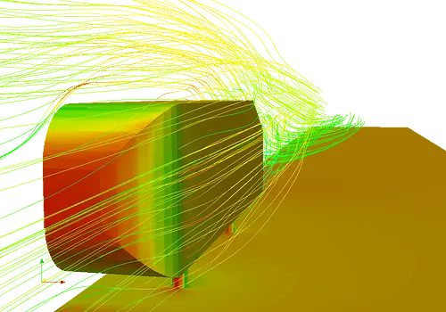
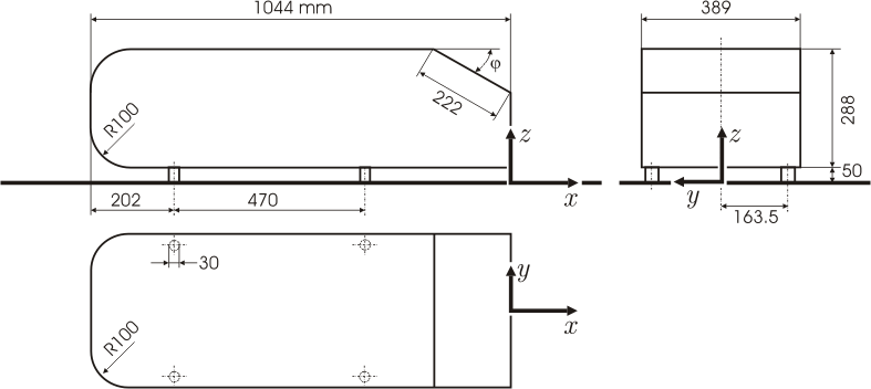
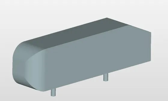
The Ahmed body is a generic car body (a simplified vehicle model). The airflow around the Ahmed body captures the essential flow features around an automobile and was first defined and characterized in the experimental work of Ahmed. Although it has a very simple shape, Ahmed body allows us to capture characteristic features that are relevant to bodies in the automobile industry.
This model is also used to describe the turbulent flow field around a car-like geometry. Once the numerical model in validated, it is used to design new models of the car.
Significance of flow seperation:
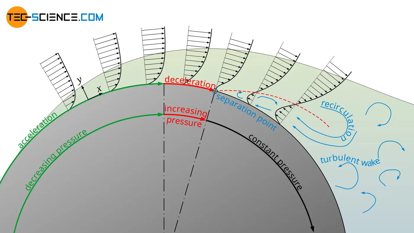
When a fluid flows around a body, forces act between the fluid and the surface due to the viscosity. These intermolecular forces are the caue for the drag, among other things. However, due to the forces acting, the surface of the solid body also tries to bind the fluid to itself. This also leads to the fluid adhering to the surface (no-slip condition). The layer above this adherent fluid layer will not be able to simply tear itself away from it, because intermolecular attraction and pressure forces also act between the layers. As a result, any flow flowing around a body is tempted to follow the profile of the surface.
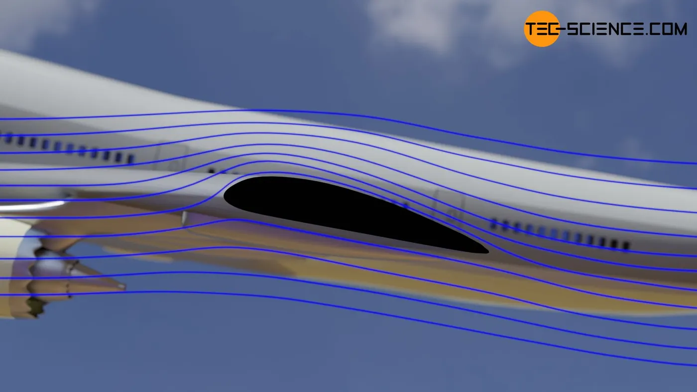
As long as the contour of a body has smooth transitions and the internal cohesion of the fluid (viscosity) is large enough to resist the inertial forces, a flow can follow the contour. A typical hydrodynamic boundary layer develops around the body, the thickness of which is largely influenced by the viscosity.
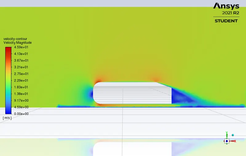
In the case of sharp transitions or when flowing around blunt bodies, however, the fluid is often no longer able to follow the profile. The boundary layer or flow begins to detach itself from the body surface. This is referred to as a boundary layer separation or flow separation. Downstream of the separation point, vortices often form, resulting in a turbulent flow. A flow separation is particularly dangerous on the wings of an aircraft, as this also causes a loss of lift and the aircraft is in danger of crashing. In aviation such a dangerous flow separation is called stall.
In the case of a boundary layer separation (flow separation), the flow can no longer follow the profile of the body around which it flows and separates turbulently from it.
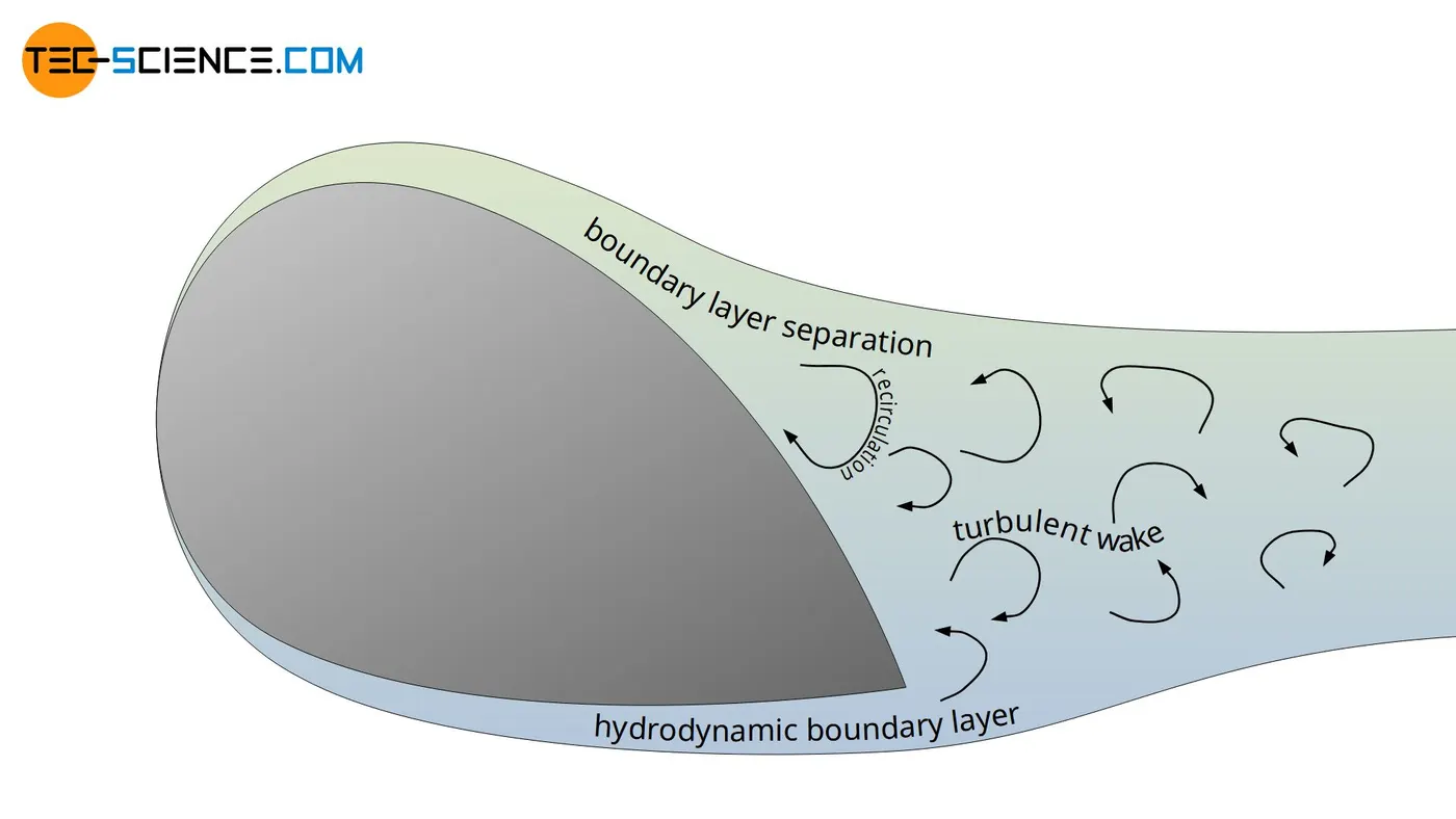
As already mentioned, the boundary layer separation is obvious at sharp transitions. However, a stall can also occur even with smooth transitions. This is the case if the flow slows down considerably when flowing around a body. As a result, the static pressure can increase so much that it suddenly pushes the flow in the opposite direction. This results in a recirculation area, which causes a flow separation. Since a deceleration of the fluid occurs with every body, the danger of boundary layer separation therefore also exists with every body around which the fluid flows!
The Reynolds number plays a decisive role here, since it describes the relationship between the existing inertial forces and the acting viscosity forces in a fluid. The higher the Reynolds number, the greater the inertia compared to the viscosity and the higher the risk of boundary layer separation. If the Reynolds numbers are sufficiently high, even with streamlined bodies, flow separation will eventually be unavoidable.
Simulating the flow over Ahmed body:
We are going to simulate the flow over Ahmed body and calculate the drag coefficient. The simulation will be performed in 3 cases in which we will mesh the Ahmed body by different number of elements. The following steps will be involved in simulating the flow in Ansys Fluent:
- Geometry Preperation.
- Mesh Generation.
- Problem Set Up.
- Solving.
- Post-processing.
1. Geometry Preperation:
The geometry of the Ahmed body in the Ansys Spaceclaim is shown below:
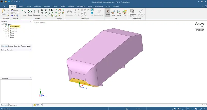
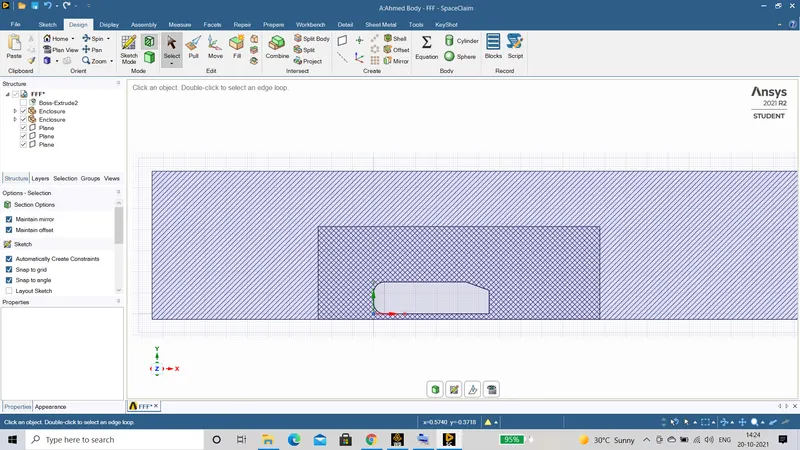
Now we wll make 2 enclosures around the Ahmed Body usind the enclosure command. To do that go to Prepare `->` Enclosure and then enter the dimensions.
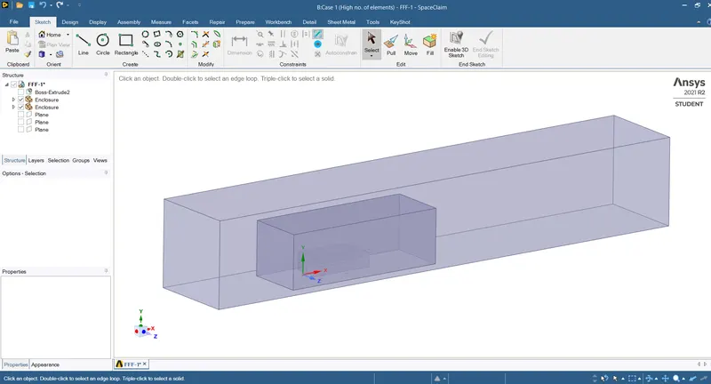
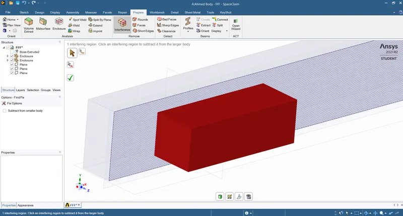
Now we will check if there is an interference occuring between the enclosures by the section plane.
We can clearly see that there is an interference between two enclosure and to remove it we will go to Prepare`->`Interference and click on the green tick button to remove the interference.
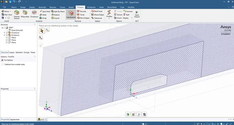
We are done for the geometry preperation and now we are ready to generate the mesh.
2. Mesh Generation:
In the mesh generation process we will create the mesh in 3 different bodies:
- Bigger Enclosure.
- Smaller Enclosure.
- Ahmed Body.
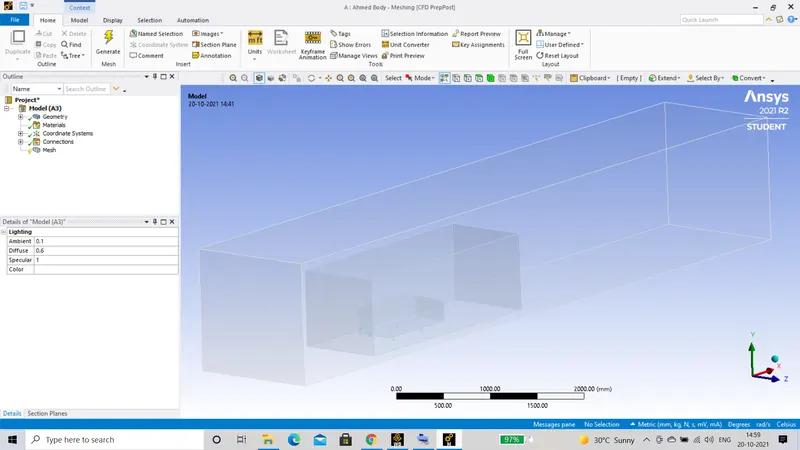
Firstly, we will mesh the outer or bigger enclosure in which the mesh size will be 100 mm and mesh type will be Hexa mesh.
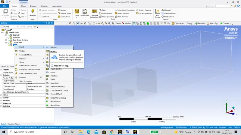
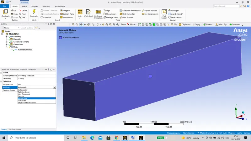
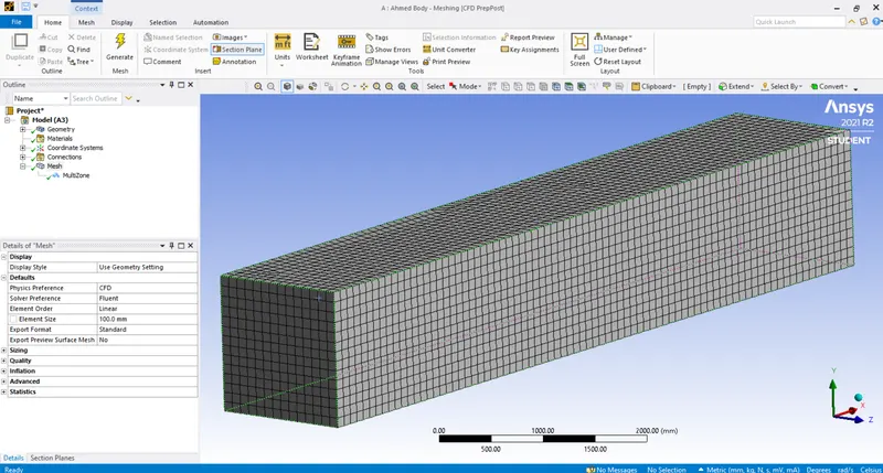
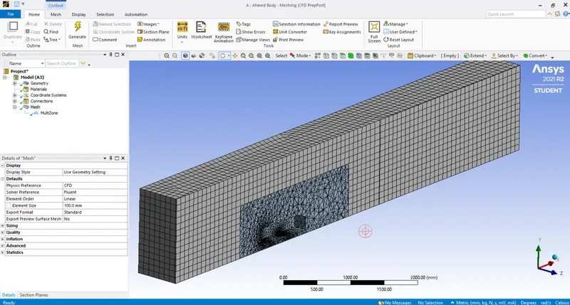
As we can see that all of the geometry is meshed and the outer enclosure is meshed as we desired. Now we just have to change the sizing of the inner or smaller enclosure and the Ahmed body.
For the smaller enclosure we will first go to Mesh `->`right click `->`Insert `->`Sizing and select the smaller enclosure body. After that we will enter the element size be 50 mm and then will generate the mesh.
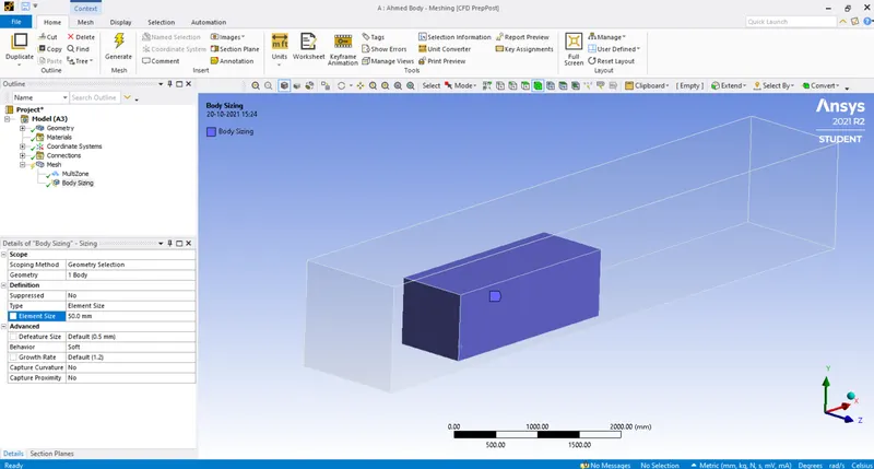
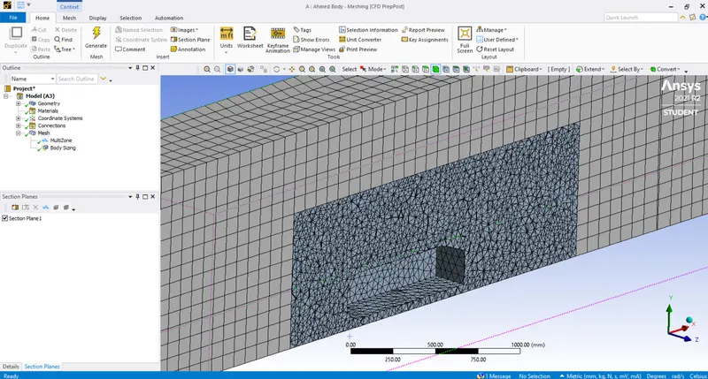
Now for the final part we will be generating finer mesh on the Ahmed body because that's where the simulation actually depends and also the calculations of drag coefficient will be done on this part.
To do that we again right click on the Mesh option the Insert `->` Sizing and selecting all the faces of the body. After that we will define the element size and then generate the mesh.
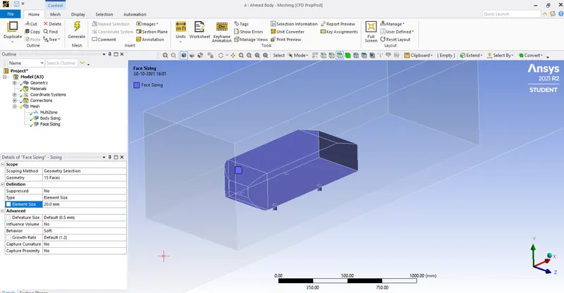
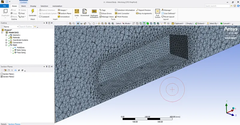
In the last step we will create an inflation layer around the Ahmed body enclosure to form a body fitted mesh.
To do that we will right click on the Inflation option in the details section and select the Ahmed body faces. After that select inflation option as Total thickness and enter the maximum thickness as 12.44 mm.
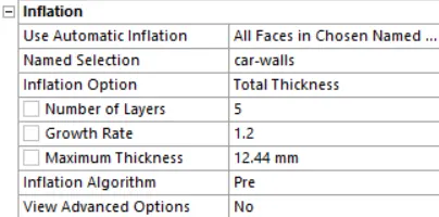
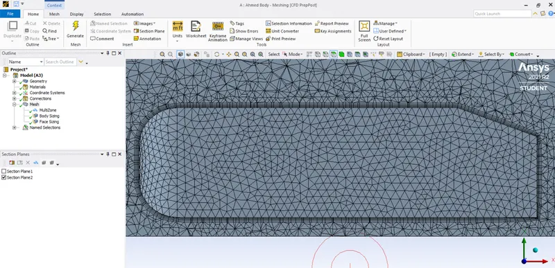
Now we have successfully generated the mesh to the geometry and now we are going to make 3 cases based on the number of elements generated during the mesh.
To do that we have changed the element size of Ahmed body enclosure to 12 mm,20 mm and 45 mm. In this way we have created 3 cases to run for the simulation with 3 different number of elements.
| Cases | Element Size of Ahmed Body | Number of Elements |
| Case 1 | 12 mm | 494800 |
| Case 2 | 20 mm | 282998 |
| Case 3 | 45 mm | 196990 |
3. Problem Setup:
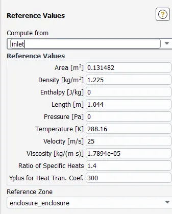
In problem setup we first set the reference values by changing the Area of the Ahmed body and the length of the body.
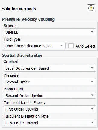
After that we will select the solver scheme as SIMPLE.
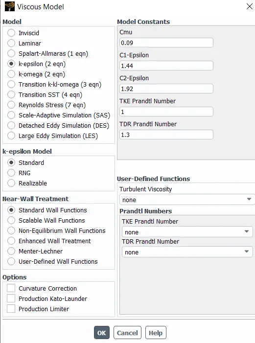
Now we will choose our Viscous model as Standard K-Epsilon because we are calculating the turbulent flow over the AHMED BODY.
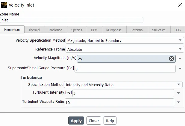
As the velocity of flow over Ahmed body is 25 m/s, we will specify this in the boundary conditions as inlet velocity.
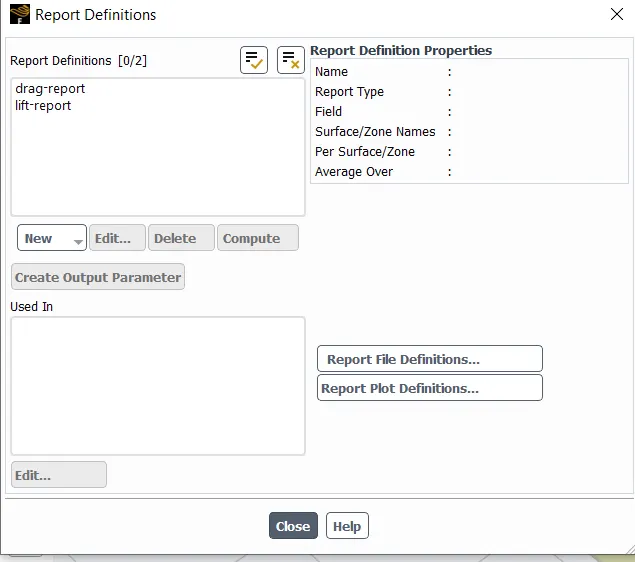
In the solution tab we will generate the two reports as Drag and Lift.
After that we will initialize the simulation at t=0.
After initialization we will create a plane on z axis which cuts the middle of the geometry. To do that we will go to the Results tab and select the Create `->` Plane option and name it as Cutplane-z.
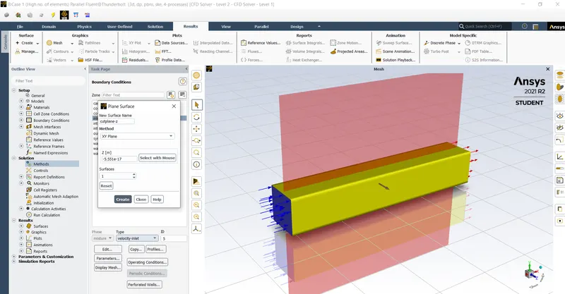
The purpose of creating the cutplane is to create a 2D geometry of the body so that we can project the velocity contours on it.
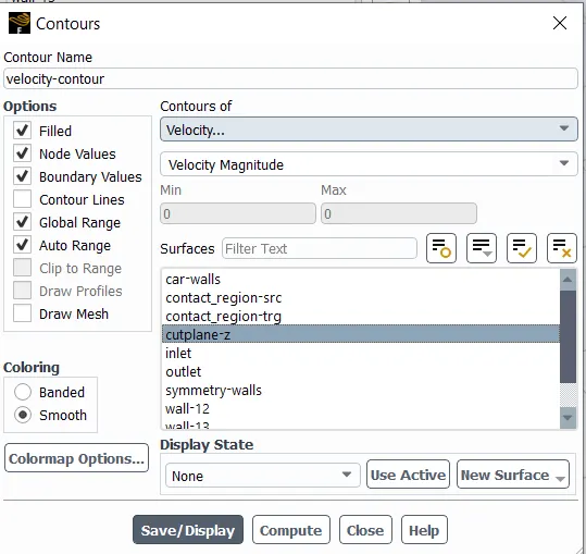
To create the contours click the Contours `->` New option and then name the contour as the velocity-contour at cutplane-z.
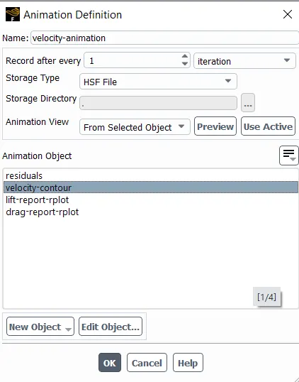
Now we have to create an animation file of the velocity contours.
Hence we are done with the problem set up adnd now we are ready to run the simulation.
4. Solving:
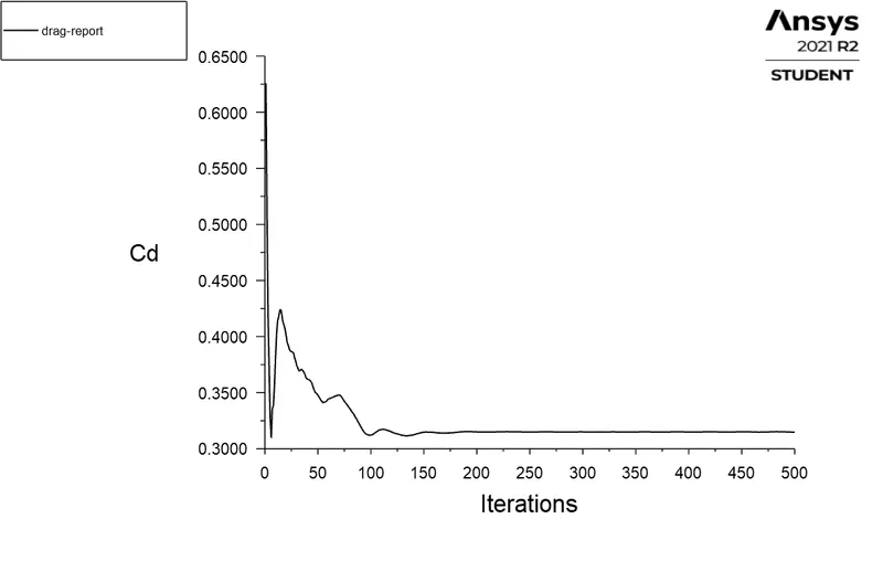
We will run the simulation for 500 iterations and analyze the results for 3 cases as stated in the Mesh generation section.
| Cases | Element Size of Ahmed Body | Number of Elements |
| Case 1 | 12 mm | 494800 |
| Case 2 | 20 mm | 282998 |
| Case 3 | 45 mm | 196990 |
5. Post-processing:
Case 1:
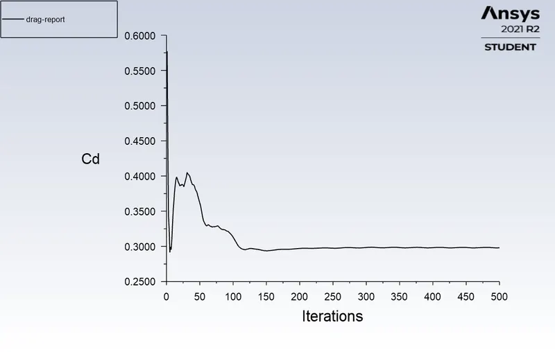
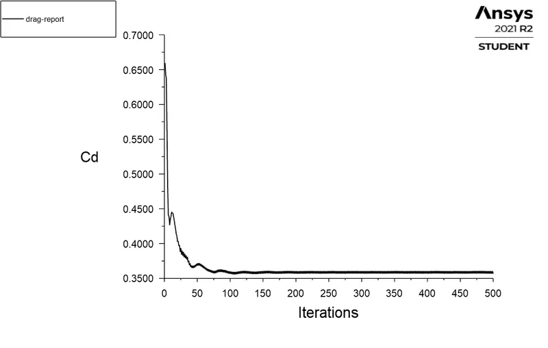
Drag plot:
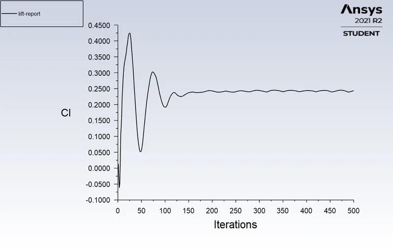
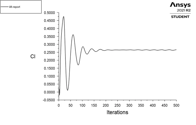
Lift plot:
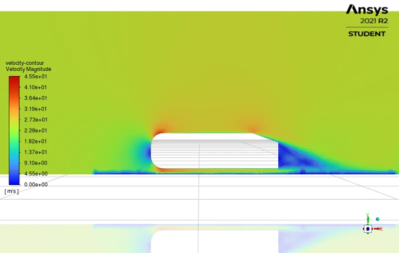
Velocity contour:
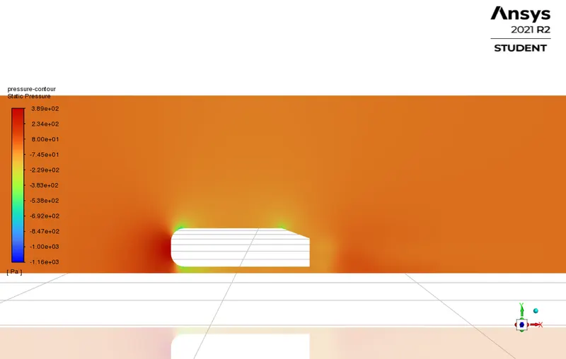
Pressure Contour:
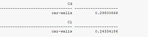
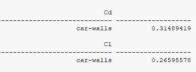
Report:
Case 2:
Drag plot:
Lift plot:
Velocity Contour:
Pressure Contour:
Report:
Case 3:
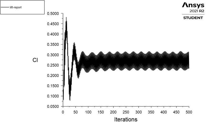
Drag plot:
Lift plot:
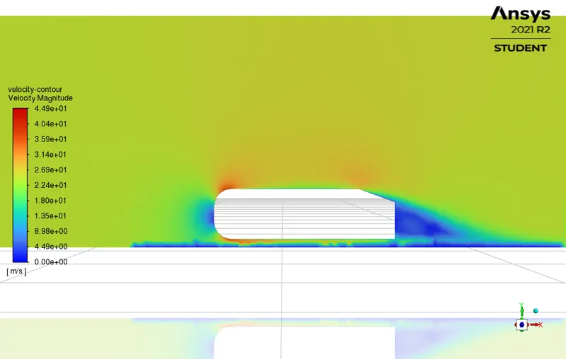
Velocity Contour:
Pressure Contour:
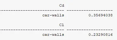
Report:
Observation:
By performing the above cases we have observed the follwing things:
| Cases | Element Size of Ahmed Body | Number of Elements | Drag Coefficient | Lift Coefficient |
| Case 1 | 12 mm | 494800 | 0.30 | 0.24 |
| Case 2 | 20 mm | 282998 | 0.32 | 0.27 |
| Case 3 | 45 mm | 196990 | 0.36 | 0.23 |
- In case 1 and case 2 the results are nearly closed to each other because the number of elements of the mesh are considerably higher but in case 3 there is huge drop of the number of elements which produced the results with a huge gap which shows the increment in errors. So if the number of elements are high the more accurate the result is.
Negative Pressure in the wake region:
The negative pressure in the wake region is caused by the 2 reasons:
1. Due to the boundary layer seperation, a vacuum region is generated and because of this there is a negative pressure in the region.
2. Due to recirculation zone there is a very low pressure region generated behind the Ahmed body.
Conclusion:
- The significance of Ahmed body is explained.
- The importance of flow of seperation is discussed.
- The simulation of flow over Ahmed body is successfully executed.
- Drag coefficient and lift coefficient graphs have been plotted along with the velocity and pressure contours.
- The reason negative pressure in the wake region has been explained.