Drop test
AIM:-
To perform a Drop test Simulation of a mobile phone on the rigid table with suitable Parameters and Boundary conditions and plot the results in the form of a Graph.
PROCEDURE:
1. Open the Drop_test_onlymesh.k File Given.
2.The File Only Consists of the nodes and elements of the Mobile phone and the table.
3.The Unit system Followed here is Kg, mm, ms
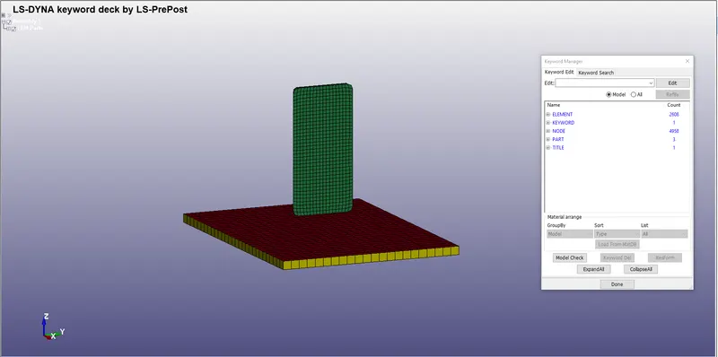
4.To perform the Simulation, materials, Section, initial velocity, Contact Interface, Boundary conditions, Output For the Following Must be Specified.
1.ASSIGNING MATERIALS:-
For Defining materials go to Keyword Manager > All> MAT > Select the Material card and define the material properties like mass density, Young’s modulus, Poisson’s ration, Yield point stress value, and other required quantities for both the material cards.
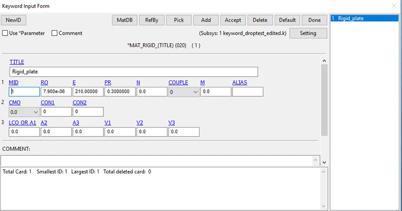
1.Two Different Materials are Assigned to the Phone and the table.
2.For table An rigid Material is Given, Mat_20 Is assigned with Properties of Steel.
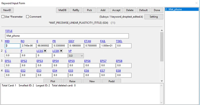
3.For The Phone Aluminium alloy material is selected from the Database Survey. Mostly the Mobile Phones are made of plastic, silicon, aluminium..etc. since the Material of the Plate is Rigid Subsequent material Aluminium alloy is Selected for the Phone.
4.for the Mobilephone MAT_24_Piecewise_Linear_Plasticity Card with properties of Aluminium alloy.
2.SECTION CREATION:-
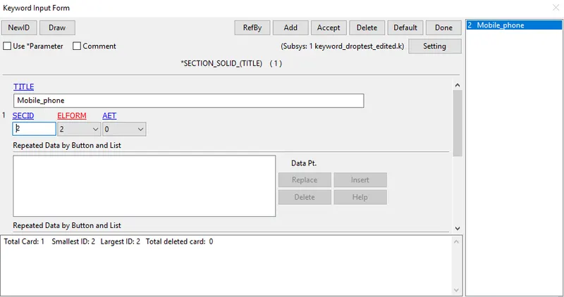
1. As the Mobile Phone is solid and the rigid plate is Shell Component Two Different sections for the Phone and Plate are Created.
2. For Defining Section Go to Keyword manager > All > Section > Solid/Shell
3. Defining Shell Section Card for Rigid Plate, with element Formulation-2
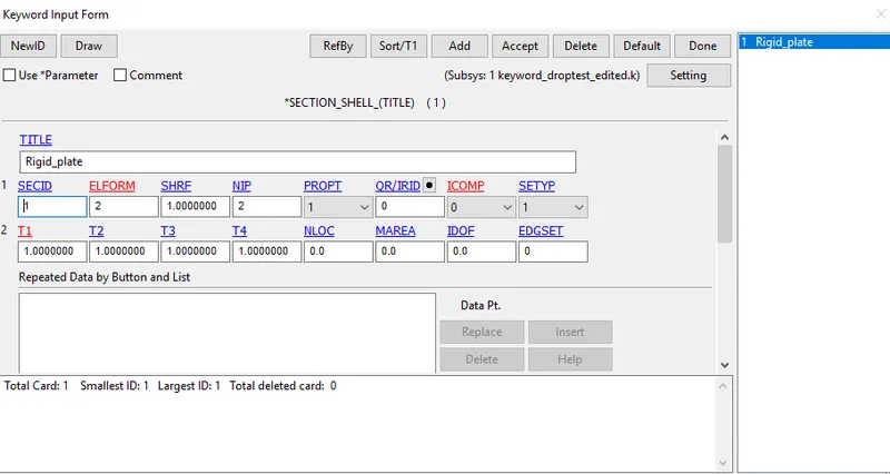
4.Defining Solid Section Card for Rigid Plate, with element Formulation-2
3.Specifying the Material and Section ID to the respective part IDs.
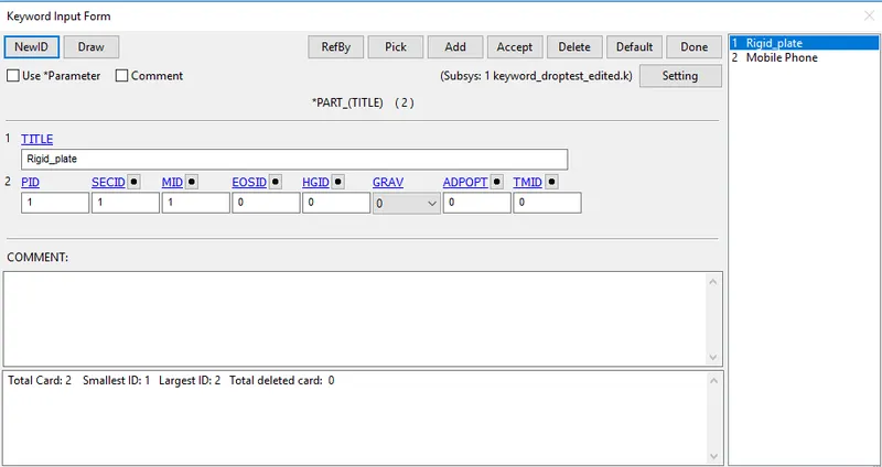
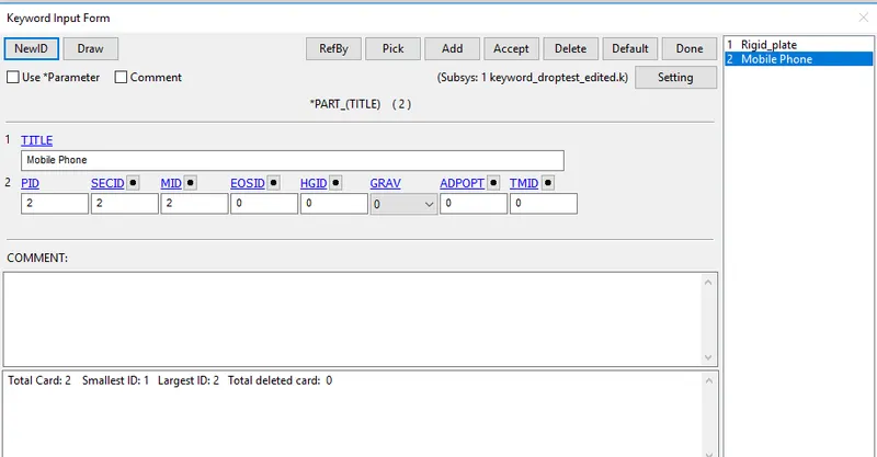
1. In parts, we basically assign material and section with their proper ID for every part individually.
2.Assign the Section-Id and Materials Individually as Part-1 and 2.
3. For Creating part Go to Keyword manager> Model > Part and assign the Materials and Sections.
4.BOUNDARY CONDITIONS:-
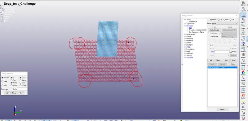
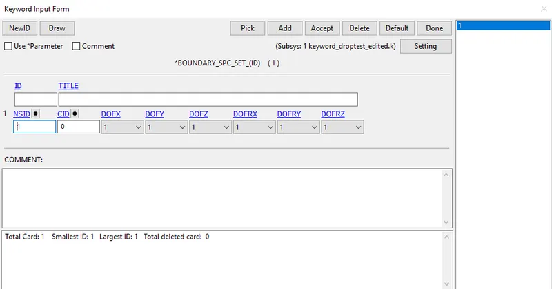
1. As the plate is Not Fixed it's Fixed Using SPC ( Single Point Constrained )Nodes at each Corner of the plate.
2.To Create Spc go to Create entity > Boundary > Spc > Create .
3. Select Four Nodes At each Corner and Their DOF's are set to 1, Dof=1 means It's movements are Locked in all Direction both translationally and Rotationally.
5.INITIAL VELOCITY:-
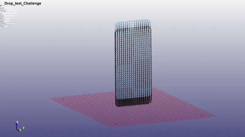
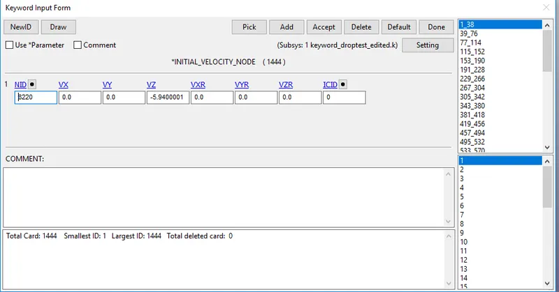
1.Initial velocity Is defined to the Phone By Keyword manager > New > Initial > Velocity. select the Nodes By part in the Mobile Phone And Click Apply
2. Since the distance between Cellphone and plate is around 20 mm so velocity `V=sqrt2gh` is used.
3.Velocity of 5.94mm/ms Is given to the Mobile Phone.As Mobilephone is dropping along negative z-direction so Vz= -5.94 mm/ms is given as initial velocity by selecting all the nodes of the Mobilephone.
6.CONTACT INTERFACE:-
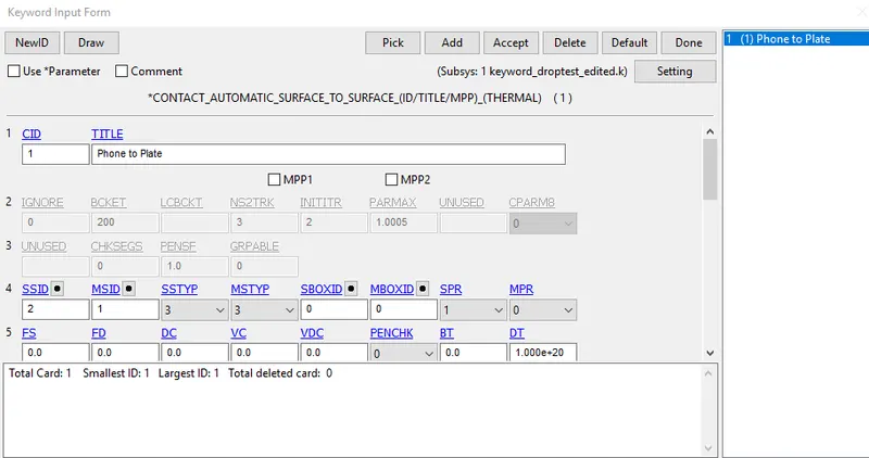
1. Contact Interface Is created By Model and Part > Keyword Manager > Contact > Automatic Surface to Surface.
2. The slave segment type (SSTYP) and master segment type (MSTYP) is defined by the Part IDs, select the Mobile phone part as a slave and the Bottom plate as Master.
3.The Parameters are given as default and The Value of SOFT=1 is assigned.
7.CONTROL CARDS:
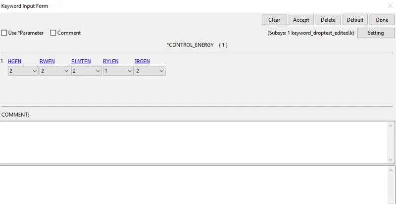
1. Control cards such as Control Termination, Control energy are specified.
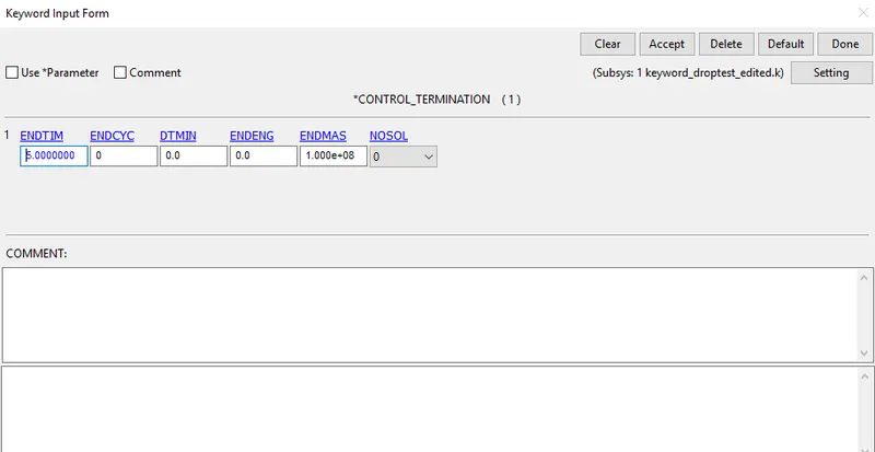
2.Termination time defined by using *CONTROL_TERMINATION card
3.Set Model and Part > Keyword Manager >Control> Termination to 5ms
Control-Energy:
1. control energy is defined to control Hourglass energy occurs during the Simulation
Model and Part > Keyword Manager >Control> Energy and give the appropriate parameters.
8.OUTPUT REQUEST:
1. To view the results of Simulations Following Steps are Specified.
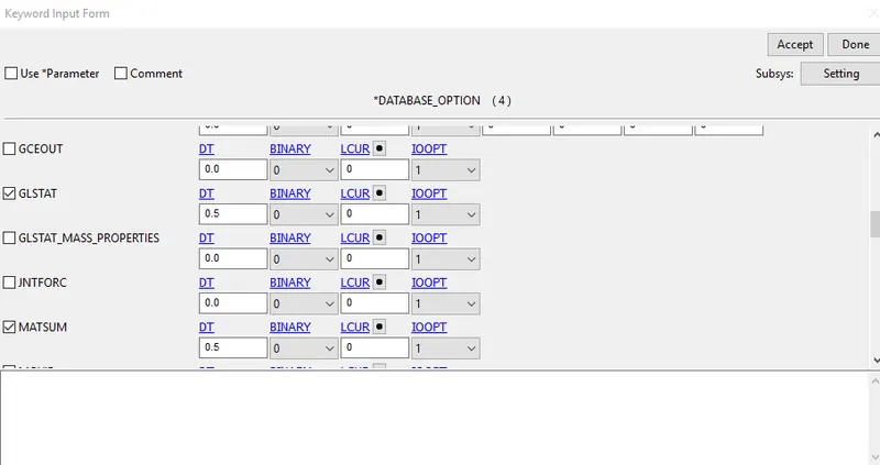
2. Go to Keyword Manager > Database > ASCII select GLSTAT, RCFORC with DT 0.5
3. GLSTAT card is enabled with 0.5 output time interval which gives global energy data like Kinetic Energy, Internal Energy, and other types of energy, RCFORC card is enabled with 0.5 output time interval which gives forces due to contact between two parts mobile phone and bottom plate.
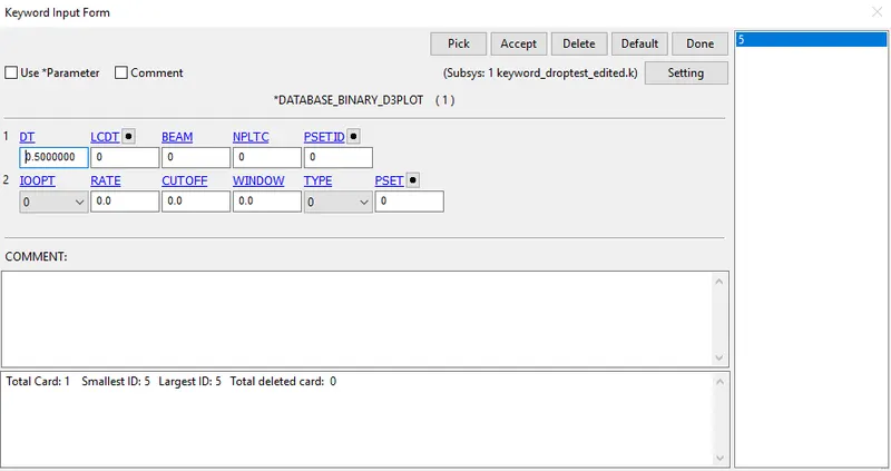
4. Go to Keyword Manager > Database > Binary D3plot >DT 0.5 It prints the Output file at each 0.5ms. The D3PLOT card gives animation and other post-processing data after the simulation.
9.Run The Simulation.
1. Save the Keyword In a separate Folder And Run the Simulation In LS-Dyna manager.
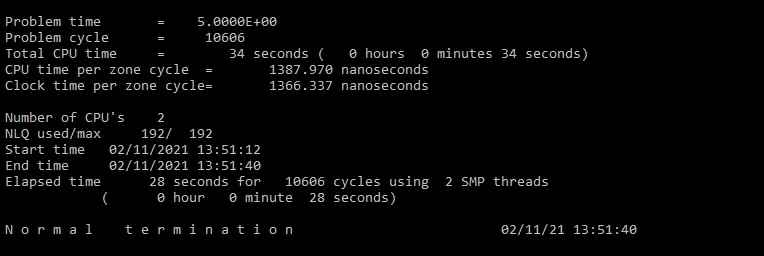
2. After Running the Simulation Open the Binary D3plot file in Ls Dyna pre-post.
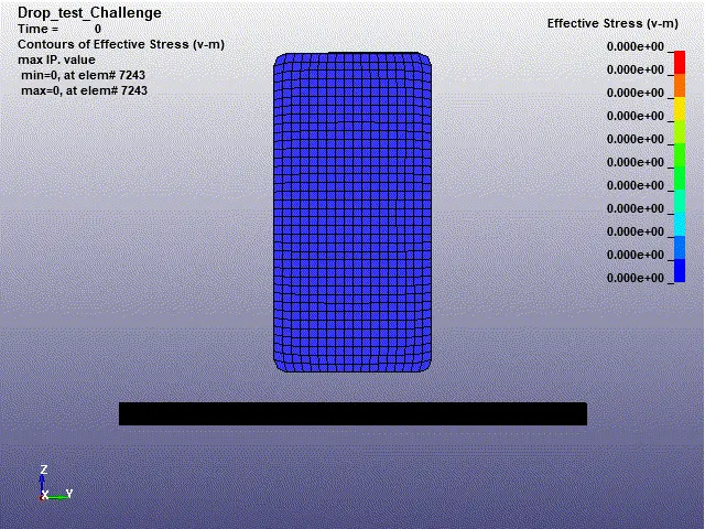
3. From the Gif, we can see that there is no Impact till 3.3s After that The phone Bounces at 3.9s
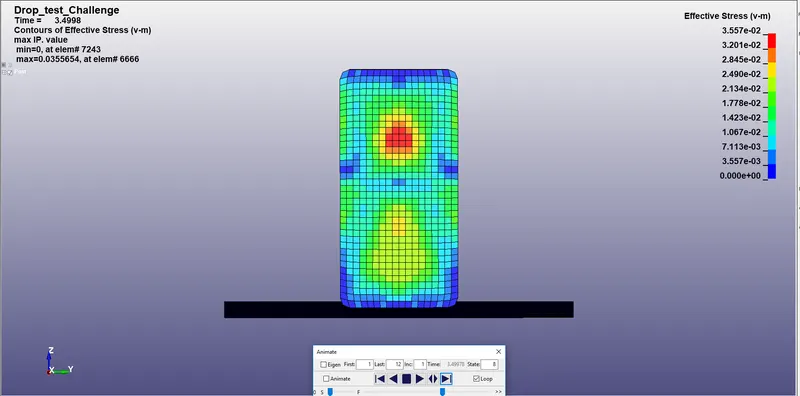
The Maximum Stress acted on the element is 3.557e-02gpa at 3.4498 sec in the element6 6666
The Minimum stress on the element is 0.000+00 at element 7243.
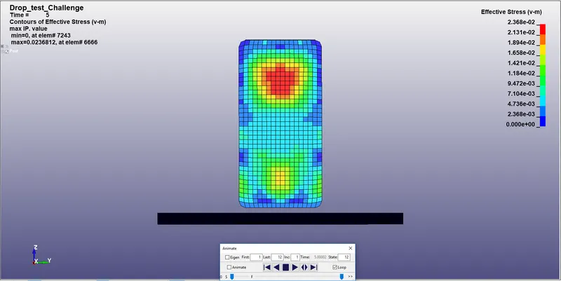
As we can see the effective stress of 2.368e-02gpa is acting On the middle of the phone at 5s even after Bouncing.
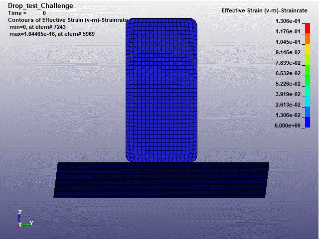
Strain rate:-
10.Plotting Graph:-
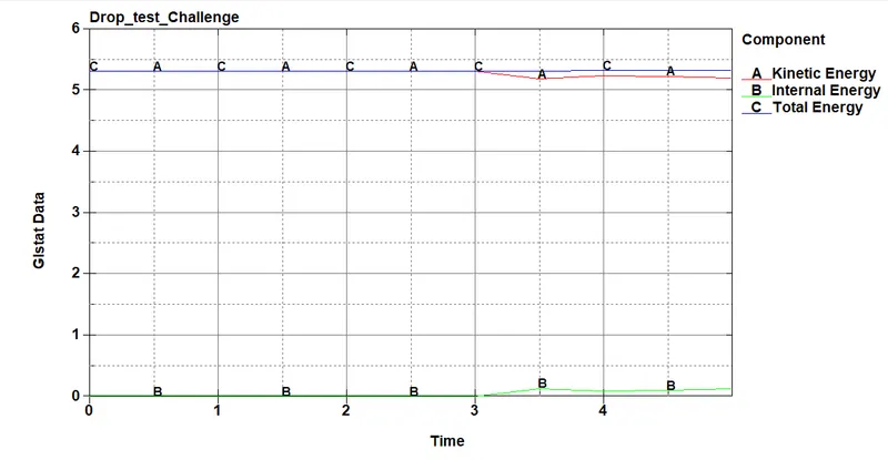
Energy Graph:-
From the Graph:-
- There is no impact till 3ms After 3 ms we can see Deflection in Both Kinetic energy and Internal energy
- As we can see the Internal energy produced By the Rigid Plate is Almost the same as the Kinetic energy
- The Total energy is remaining constant Throughout the process, The law of conservation of energy is satisfied.
Hourglass energy Graph:-
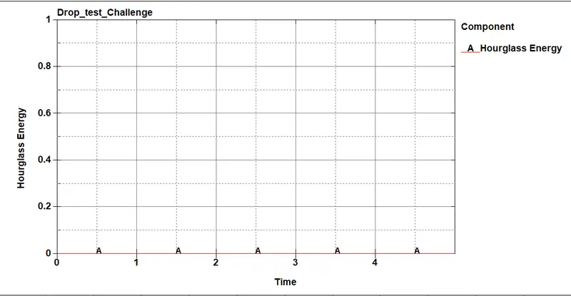
From the Simulation, we can say that there is no Hourglass Formation as the Line remains constant
Sliding Energy Graph:-
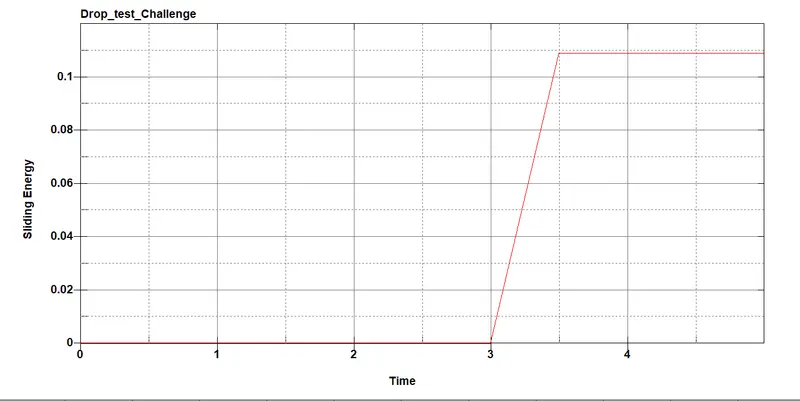
From the graph, we can see the Sliding energy rises at 3ms since the Plate is rigid and Opposing force Is created During the Time of Impact.
Interface Graph:-
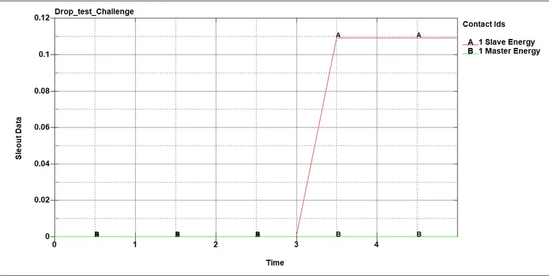
- From the Graph, we assigned the Phone as the Slave and the rigid Plate as the master.in Automatic surface to surface Contact.
- Whenever The Slave reaches The master Gap a penalty formulation created as the slave nodes are pushed away from the Master.
- In the Graph The phone impacts the plate at 3ms. so the Penalty (spring) is formed and there is rise at 3ms.
CONCLUSION:-
1. The complete simulation keyword file is generated from the primary file contained just nodes and elements of two parts.
2. Added the keywords like material, initial velocity, section, boundary conditions, controls, database, and contact are properly assigned to create a basic solver deck to simulate a drop test.
3. The study of mobile drop tests is been carried out and outputs for Vonmisses stress, Effective plastic strain is obtained by running the simulation, and energy, resultant force, strain graphs are also plotted.