Week - 3 Drop test Challenge
AIM:
To perform a drop test for the given model.
PROCEDURE:
1. Import the model File > Open > k.file > OK.
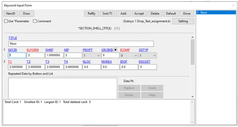
2.The selection properties for the floor is selected as shell elements with element formulation ELFORM 2, and thickness is given as 2mm. Integration point is selected as 2.
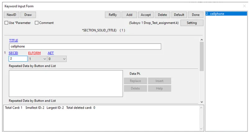
3.The cellphone is made up of 3D brick elements and default element formulation of constant stress solid element is selected.
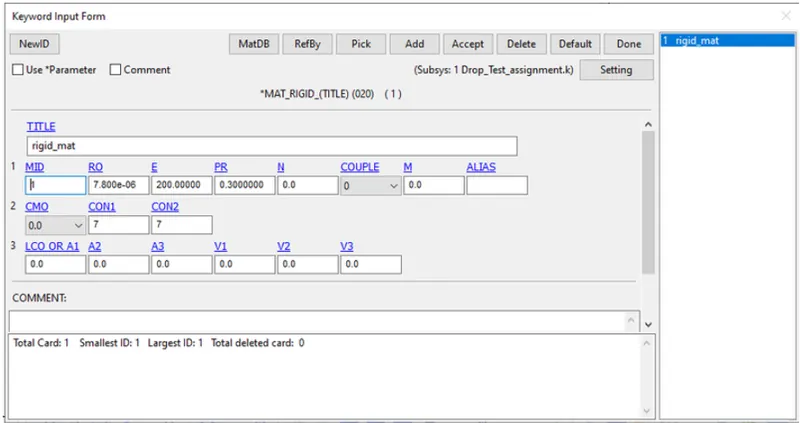
4.The material properties of rigid shell elements and deformable solid element are follows. The values entered here are arbitary as the properties have not been specified.
For rigid floor:
Density : 7.800e-06 units
Youngus Modulus : 200 units
Poisson's Ratio : 0.3
Initial velocity:
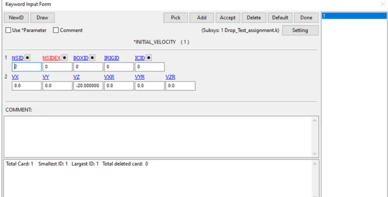
Since the cell phone is being dropped with some velocity the intial velocity is defined for all the nodes of the deformable body by creating node set ID. A value of 20 units is give in negative z direction.
Constraint:
The floor is rigid and the constraint is already defined. Since the floor is fixed, the constraint can be defined in the material card itself. The CON1 representing the translational displacements is slected as 7 which denoted contrained in all three directions and CON7 representing rotatiions which is selected as 7 which constraints in all three rotational degree of freedom.
CONTACT:
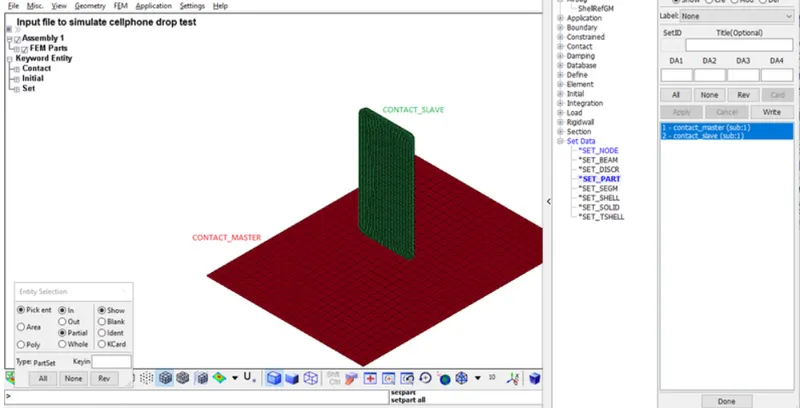
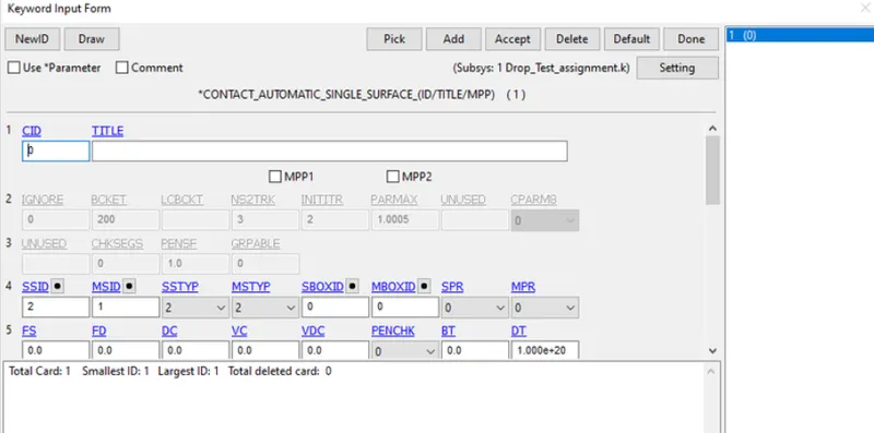
An automatic single surface contact is defined to study the impact of cellphone droped on the floor. Master and slave components in the form of segment set, node set, part set or shell element ID are to selected and their type have to be accordingly selected.
Control:
Under control the termination card is defined for specifying the end time/termination time.
Database:
Binary D3Plot is written for every 1 unit interval time.
ASCII files and binary files of Global statistics, material energies, sliding interface energies are requested to written for every 0.1 unit time to study the differnet energies during the impact.
Post Processing:
Various contour plots are plotted to check for sanity of the problem being solved .
Strresses along a particular direction, Von Mises stress can be checked form the fringe tab. Variouos plot of stress, deflection can be plotted form the fringe tab and requested to be written for dt time interval.
OUTPUT:
After running the simulation the results are plotted.
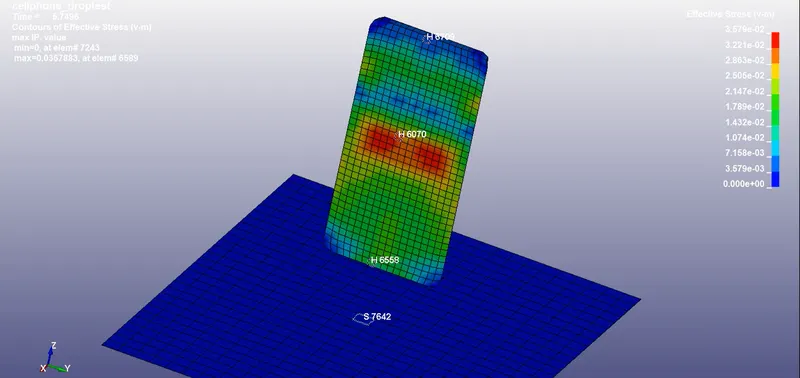
At the moment of impact the cellphone experienced maximum stress is 2.294e-01 Pa and minimum stress 2.294e-02Pa.
The ground is set to rigid with constraints on all directions in both translation and rotaion.
RESULT:
Thus the drop test of cellphone is stimulated with velocity and the plots are plotted sucessfully.
DRIVE LINK: https://drive.google.com/drive/folders/18ooQZZS2UAnqA09zYTBTk-pRAxRiu84p?usp=sharing