Week - 3 Drop test Challenge
Introduction:
A drop test is a test designed to examine the structural integrity of a product. Drop tests usually involve an object being dropped from a predefined height onto a floor or surface. The object being tested can be either the dropped object or the object/surface that an object is being dropped on to. In this case, a mobile phone is tested to check its ability to withstand the impact load and the energy released during the impact.
Aim:
To perform the drop test for the mobile phone.
Formulae used:
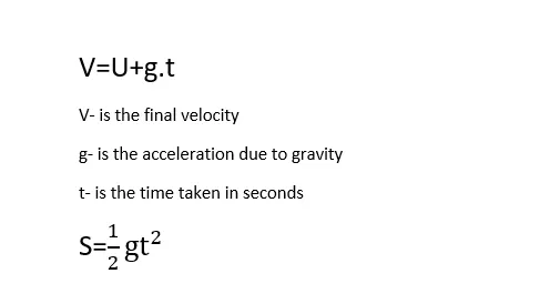
For calculating the velocity of the mobile phone during the free fall the following formulae are used.
Materials:
For Mobile phones, the material used is Aluminium-5083. Unit system is g mm ms
density=0.0027g/mm^3
Youngs Modulus=72000 g/mm ms^2
yield stress=115 g/mm ms^2
Tangent Modulus=1082 g/mm ms^2
Poisson ratio=0.33
Since the material used for the floor is concrete the concrete material is considered for the simulation.
density=0.0024g/mm^3
Youngs Modulus=41000 g/mm ms^2
Poisson ratio=0.21
Procedure:
1) Importing the Geometry file
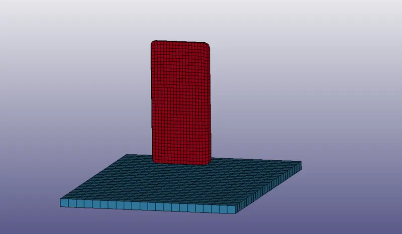
The mesh file 'Drop_test_onlyMesh.k' consist of mobile phone(body Mesh),Wall(Shell Element) and wall(solid). For the simplification purpose, the shell element is deleted. The distance between the cell and the ground is measured by using the Measure option in the element tools .Ctrl(without) and shift(with graphics update) buttons along with the mouse are used to move and rotate the model.
2) Boundary conditions
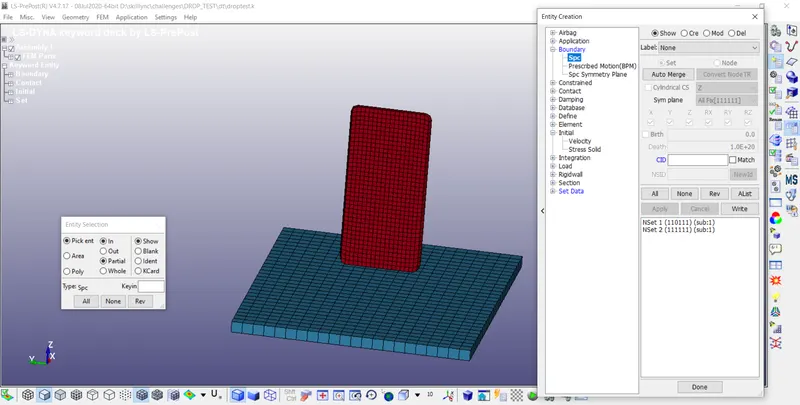
The boundary condition for the model is defined in the Entity Creation dialogue box. For defining the boundary under the "spc option" the required model is selected by using the Entity selection dialogue box. For the ground, all the DOF's are fixed and for the phone, except z translation, all other DOF's are fixed.LS Dyna automatically saves the data as a set. The initial velocity of the phone is defined in the Keyword Manager dialogue box. Since there is no provision for selecting the model in the Entity creation Dialogue box.
3) Initial Condition
Since the phone is under the free-fall condition, It is necessary to determine the velocity of the model. The velocity of the phone is found by using the above relations. The height of the model is found by using the measure option and the value of h=19.8mm
the value of V is found to be 0.6232 mm/ms
In the keyword Manager dialogue box, under INITIAL options the value of the initial velocity is defined.NSID or Nodal set ID(defined in the boundary conditions) is used to select the model
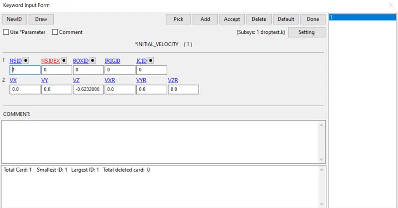
The negative direction of the velocity indicates the opposite direction.
4) Materials
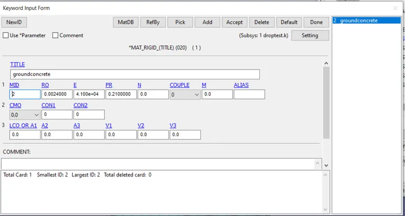
The Material for the part and the ground is defined in the MAT options. Piecewise linear plasticity is used for the phone(Piecewise linear plasticity is an elastoplastic material with an optional plastic strain threshold, and can also be modelled as strain rate dependent). A rigid model is defined for the ground.
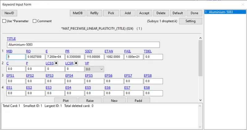
RO is the density, E- Youngs Modulus, PR-Poisson Ratio, SIGY-Yield strength, ETAN- Tangent Modulus
Since failure is not considered for this work the value of FAIL(Failure flag) is kept greater than zero
5) Section:
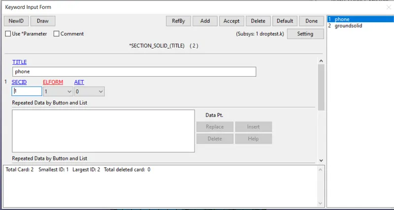
Since both phone and ground are meshed by using solid, solid is defined for the section. constant stress solid element (default) is defined in the Element formulation section.
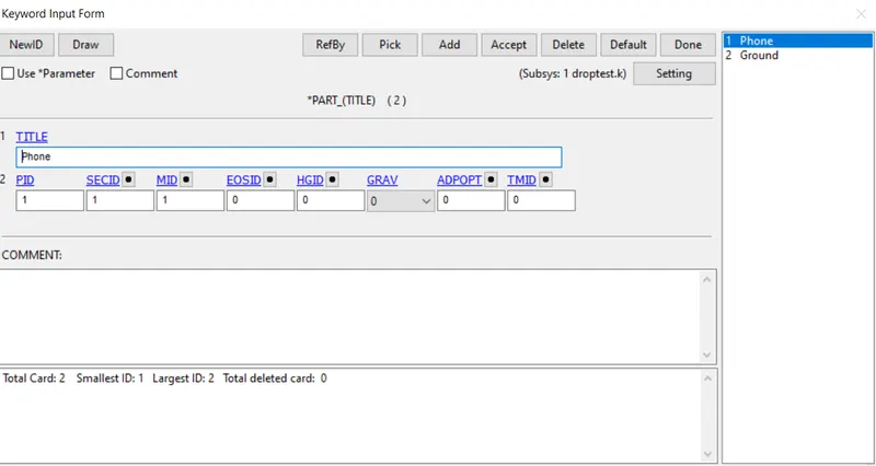
The Materials and the section are linked in the Part option. The material and the section is selected under the drop-down menu in SECID and MID.
6) Contact
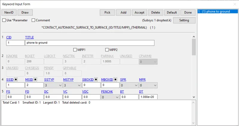
In order to estimate the reaction between the wall and the phone contact should be defined. The slave is defined as the object which has lower stiffness whereas the Master is the object with higher stiffness. In this case, the slave is the phone model and the Master is the ground. The type of slave and Master is defined in the SSTYP and MSTYP options. Create CONTACT_AUTOMATIC-SURFACE-TO-SURFACE is used to define contact between the phone and the ground.
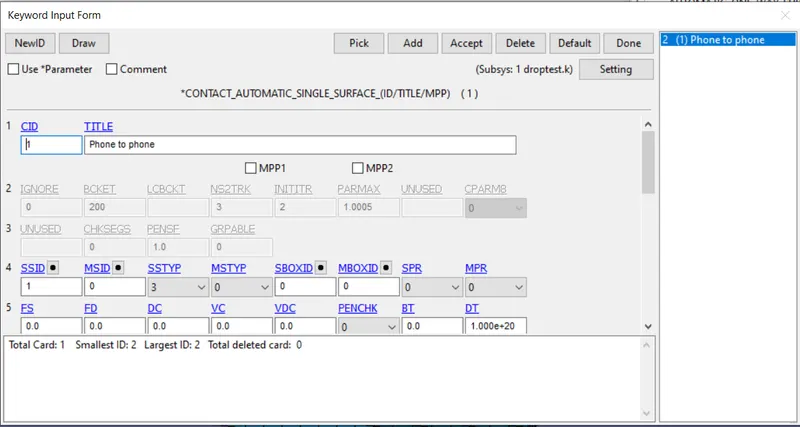
CONTACT_AUTOMATIC_SINGLE_SURFACE is used to define self-interaction between the elements of the phone.
7) CONTROL
After defining the contact, Control is used to define the End time for the simulation. Control-Termination is used to define the end time for the simulation.
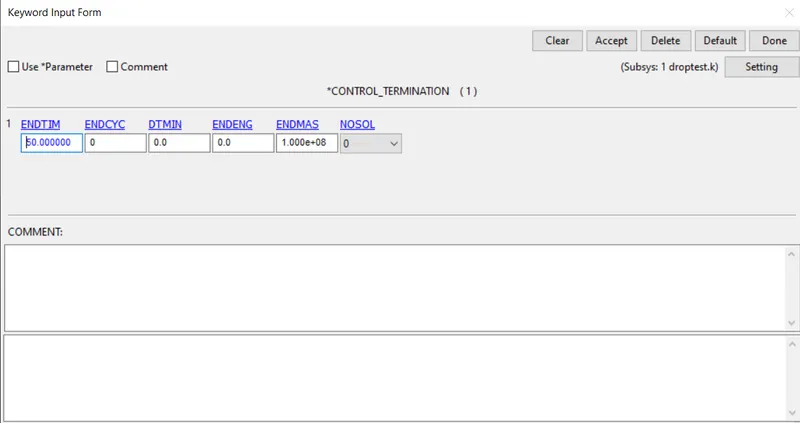
ENDTIM-50ms is used for this case.
8) DATABASE
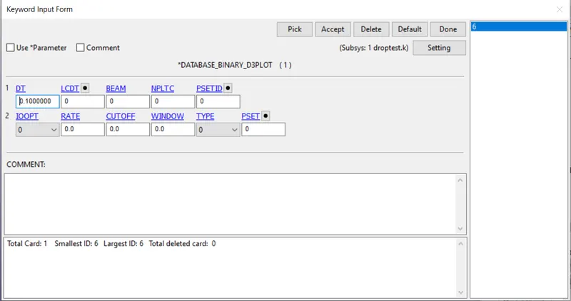
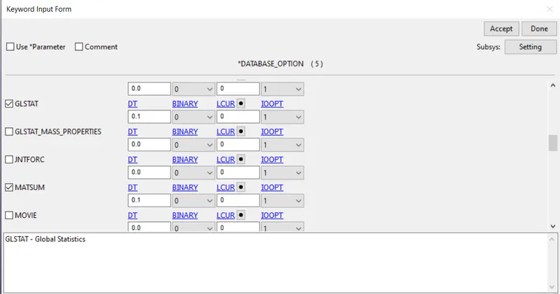
The output results are generated for the simulation by using the DATABASE command.DATABASE-BINARY_D3PLOT is selected to create a plot file and the time step for the simulation is chosen to be 0.1ms.
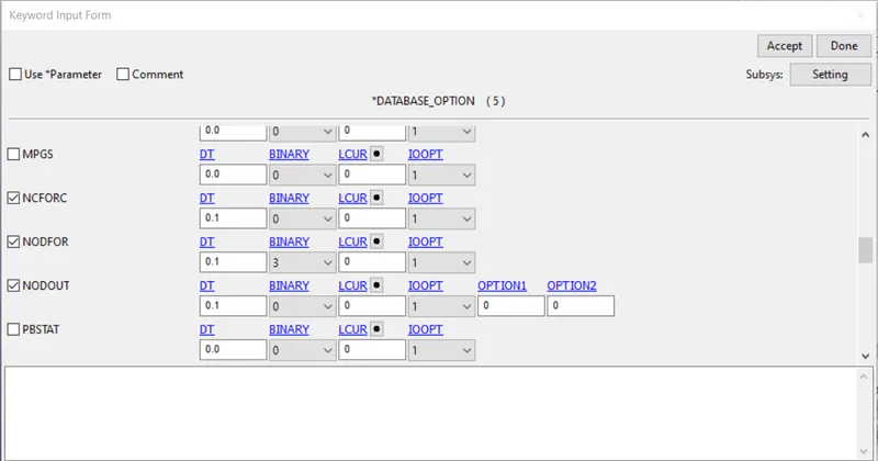
Similarly, the DATABASE-ASCII option is selected to provide additional results such as GLSTAT, MATSUM, NCFORC,NODFOR and NODOUT.
9) RUN
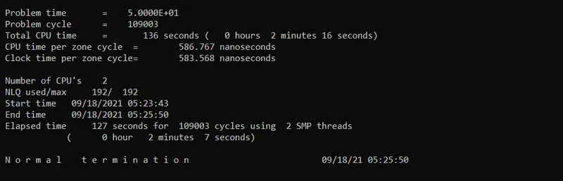
After running the simulation normal termination is attained.
Results and Discussions
Open-LS DYNA BINARY PLOT is selected to display the results.
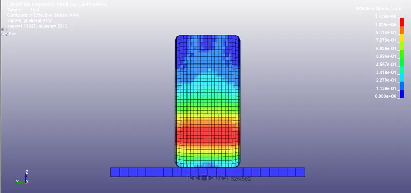
The Maximum stress generated is 1.13927 VM at 32.4ms
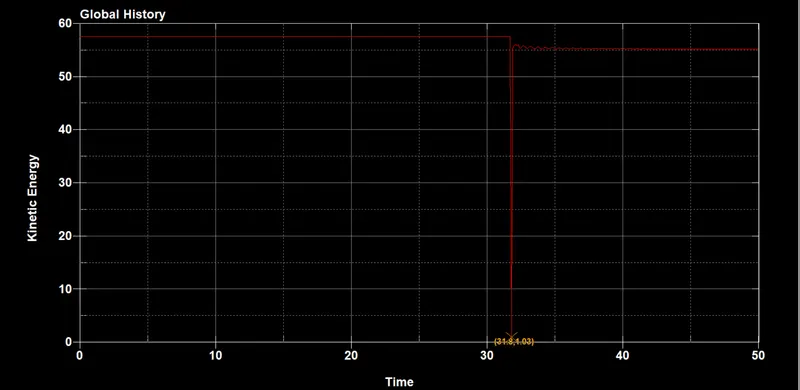
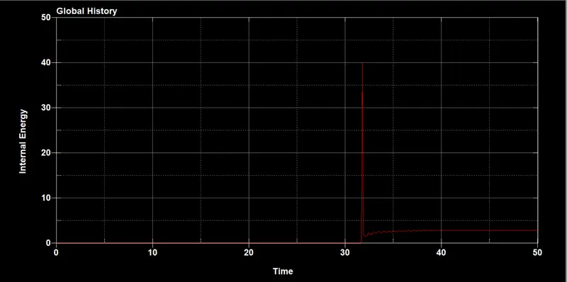
From the energy results, it can be inferred that as the phone touches the ground at 31.8ms The kinetic energy of the phone suddenly decreases to 1.03. The internal energy of the phone increases to 40.2. Hence from the plot, it can be seen that the total energy is conserved.
Conclusion:
In this work, the drop test simulation is performed for the mobile phone. Piecewise linear plasticity model is used for the simulation. Different material models can also be used to check for accuracy. The solution accuracy can be increased by using finer mesh.