Week - 3 Drop test Challenge
AIM:
To learn how to create a input deck to run the simulation and learn how to plot the results by performing a drop test analysis on the given meshed model.
Objective:
- To create the material card for respective parts by providing the properties.
- To create sections to the parts.
- Assigning the material ID and section ID for the respective part.
- Create contact interface
- Provide the boundary conditions
- Request for outputs in database cards
- Plot the results
- Conclusion
Explanation:
Import the given .k file into ls dyna prepost
Open >>> keyword file >>> select
The given .k file has 3 parts.
The shell part which is not necessary is to be deleted.
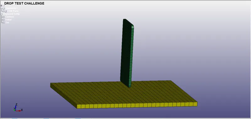
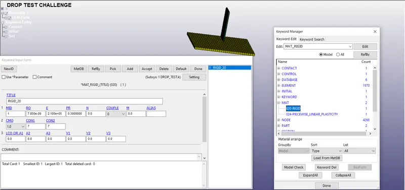
To create the material card for respective parts by providing the properties:
Go to keyword manager >>> All entities >>> Mat >>> Mat20_Rigids
Provide the Density, Youngs modulus, Poissons ratio and material ID.
As we know the bottom plate should act as rigid with all degree of freedom constrained. The CMO is activated to 1 such that constraints are applied according to global system and con1 and con2 as 7 representing the all 3 translation and 3 rotational degrees are constrained.
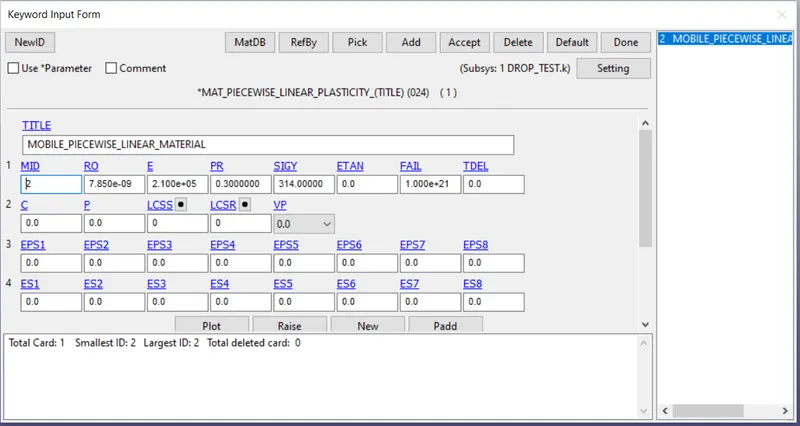
The MAT24 piecewise linear material plasticity with density,youngs modulus, poissons ratio, MID, maximum stress is provided to the mobile part as shown below.
The failure criteria of the material can be provided by maximum stress, maximum plastic strain or curve.
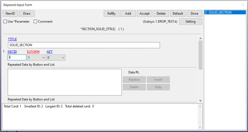
Create sections to the parts.
Provide the ELFORM value and section ID.
Assigning the material ID and section ID for the respective part.
For the mobile, The created Section Id, Material Id are added to the part.
SecID = 2, MID = 2
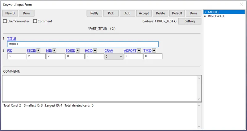
For the rigid, SecID = 2, MID = 1.
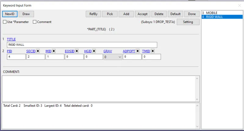
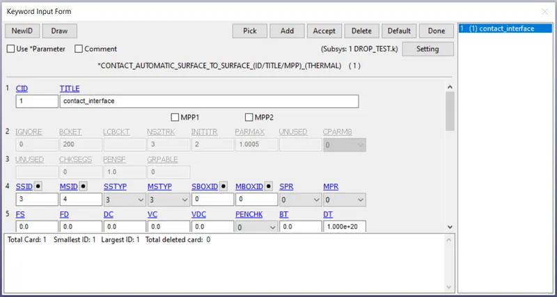
A Contact interface is to be provided to know how parts are interacting with each other.
The slave and master nodes are to be selected, represents the rigid body as master and deformable mobile as slave.
SSTYP = 3, indicating parts can be selected. in SSID we can select the part as there are only 2 parts in the domain.
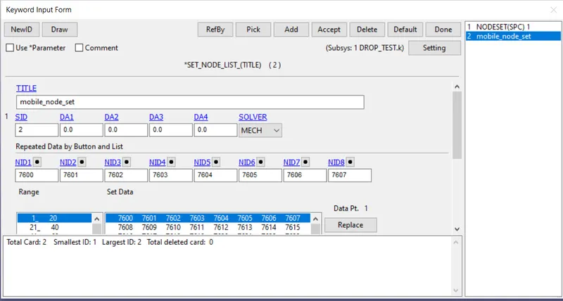
Go to Create entity >>> boundary >>> SPC >>> Create >>> NSID >>> Select by Part >>>Apply
Node set ID of mobile part is created.
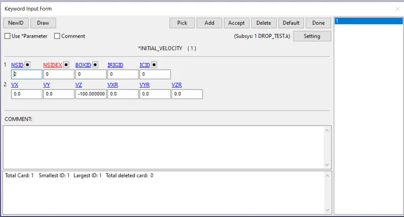
Go to keyword manager >>> All entities >>> Initial >>> Velocity.
From the global co-ordinate system, we have to provide velocity to Mobile part in negative z- direction.
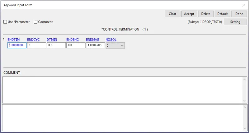
The termination time for running the analysis is to be provided.
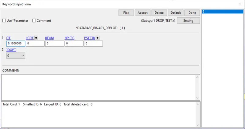
We have to request for output files to get the required plots and graphs.
Go to keyword manager >>> All entities >>> Data base >>> Binary D3PLOT, ASCII: ELOUT, GLSTAT, MATSUM, SLEOUT, SW FORCE >>> DONE
Provide the DT value of 0.1.
Save the file.
Import the file into LS RUN and run the analysis.
POST PROCESSING:
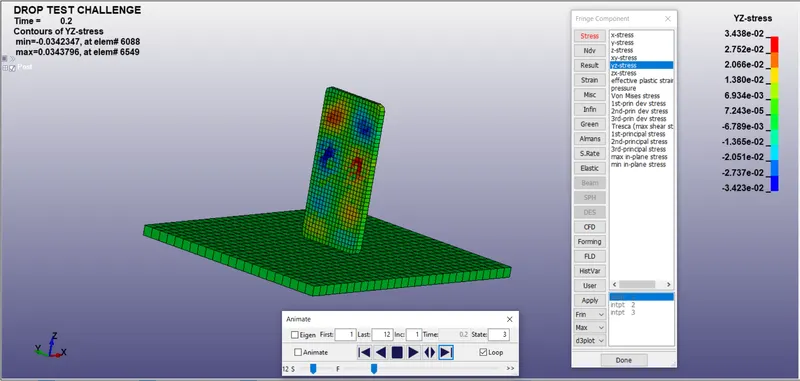
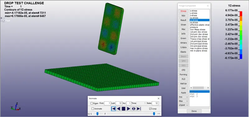
Post >>> Fringe component >>> Stress >>> YZ axis
we can see the stress contour and observe how stresses are generated and varying across the component.
3rd frame:
12th frame:
The maximum yz stress = 3.438e-2 GPA
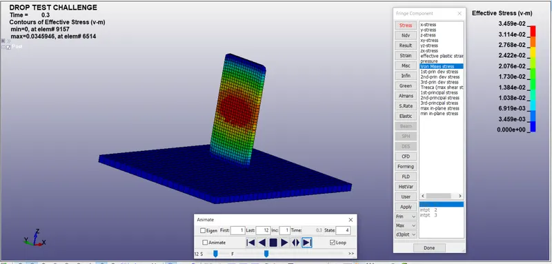
The effective stress is the von mises stress.
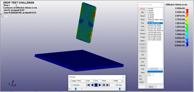
The Von-mises stress contour can be seen below:
the maximum Von-mises stress = 3.459e-2 GPA.
CONCLUSION:
- All the keywords are created from scratch and model checked.
- The maximum stresses are generated when the mobile impacts the rigid wall and then the energy is absorbed by the rigid wall.
- The bounce back of the mobile is due to the remaining kinetic energy left in the mobile after impact and bouncing