Week 3 Challenge : CFD meshing on Turbocharger
Challenge_3
Aim: For a given model of Turbo Charger geometrical cleanup need to be done and perform 2D – 3D mesh with given mesh target length.
Procedure :
- Given geometry is imported and geometry check is performed to see the geometry error like single cons, holes, etc.
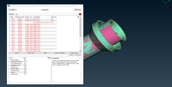
2. The glitched pink color surface is seen which has been deleted by using the delete option. Also, the Extended surface at the lower portion is deleted and recreated using the face coons option.
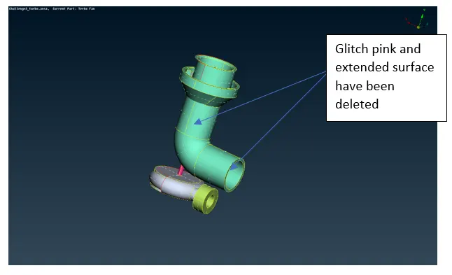
3. An open area is present in the upper portion as sown in the figure, Hot points are projected to the upper edges to created faces one by one using coons option.
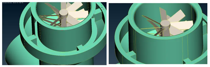 4. An extended surface which is forming a single cone as shown in the figure has been split using intersect command to get yellow edge then the extended surface has been deleted.
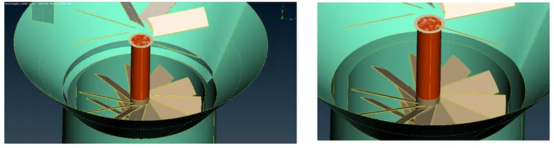
5. Overlapped orange surface have been deleted, which have created single cons which need to be fixed
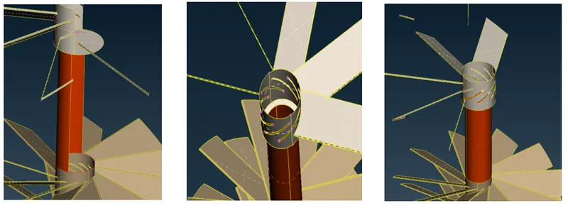 6. At the turbo housing, a surface is missing, which needs to be corrected, several hot points are created using parametric hot points, which helps to create the surface one by one.
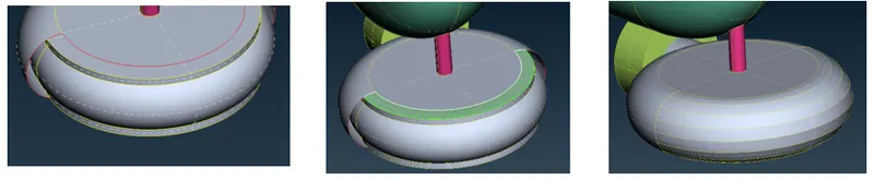
7. The pink color shaft portion is overlapping with the stage1 turbine area as shown in the figure, Extended surface is first split into two surfaces by projecting cons from the stage1 turbine, and then the extended surface has been deleted.
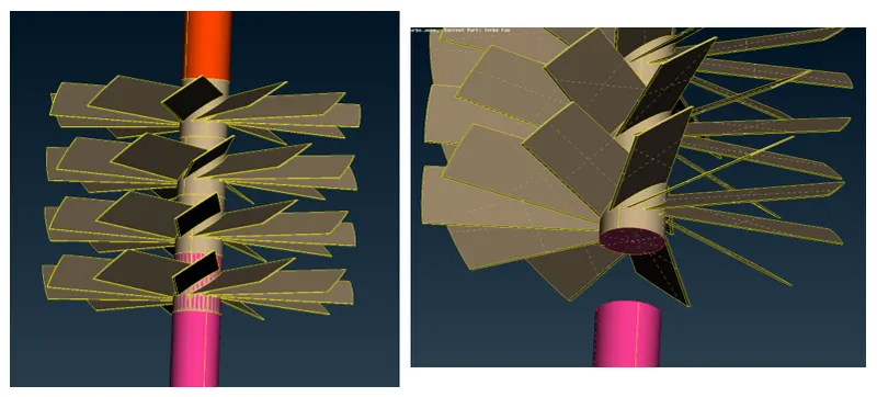
8. By deleting the extended surface, single cons and overlapped surface have been seen, which need to be fixed. Overlapped surface normal to shaft axis have been deleted to create a single volume shaft, which in turn have created many single cons, which is fixed by topo option
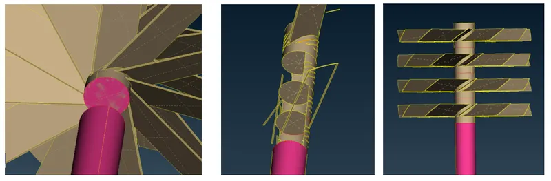
9. The overlapping surface is present at the impeller section of the shaft as shown in the figure which needs to be deleted. Single cons edge from the pink surface have been projected to blue face, then center blue face which is inside of the shaft portion have been deleted, then with the help of the topo command pink and blue surface have been joined.
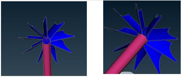
10. Geometry is all free from single cons now. To proceed for volumetric mesh, geometry needs to be closed/watertight. So to do that, extra surfaces are created using the new face command.
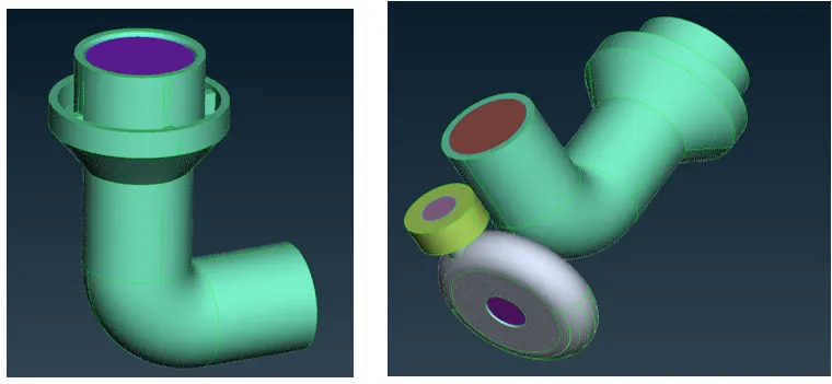
11. Quality criteria are set before doing meshing, minimum length of 3mm and maximum of 7mm is defined in quality criteria. In mesh parameter target length of 5 mm is defined, now perimeter and macros are defined as 5mm in length option. With the help of a spot mesh compressor, inlet and turbo casing are meshed as shown in the figure.
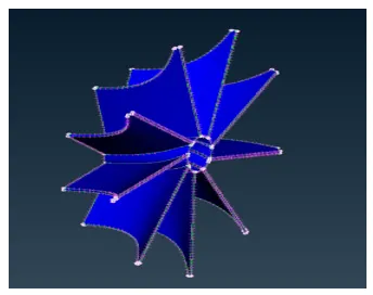
12. Quality criteria are set before doing meshing for impeller and blades, for impeller minimum length of 1mm and a maximum of 5mm are defined in quality criteria. In mesh parameter target length of 2 mm is defined, now perimeter and macros are defined as 2mm in length option. With the help of the spot, the mesh impeller has meshed as shown in the figure.
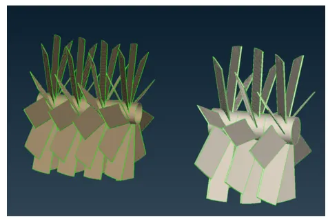
For blades, a minimum length of 0.5 mm and a maximum of 2mm is defined in quality criteria. In mesh parameter target length of 1 mm is defined, now perimeter and macros are defined as 1mm in length option. With the help of a spot, mesh blades have meshed as shown in the figure.
13. Following a similar step, the Shaft has also meshed with a 1 mm target length.
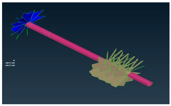
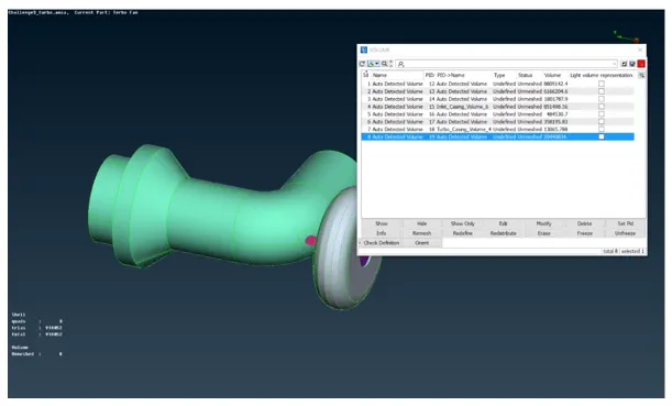
14. Since 2d meshing is done and the geometry is all free of errors, it’s time to do volume mesh. Click on the volume mesh tab and click on the define, select the whose database and click ok. It will auto-detect some volumes, and then we have to select the volume which is fluid is going to flow.
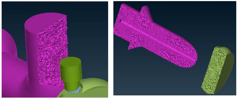
15. Now the internal volume is meshed using the tetra CFD option, and internal mesh can be seen using not option as shown in the figure.
Learnings :
- Different options are explored to remove single cons in the TOPO clean-up tab.
- Learned a different approach to remove the single cons, in which small faces are created one by one to remove the single cons if the coons option is not generating the required surface.
- Learned how to do component-wise meshing using different options of Mesh tabs
- Explored a way to define internal volume under volume meshing.
- Learned how to generate the volume mesh from 2D mesh.
Result and conclusions:
- Volumetric mesh is generated with the given target lengths.
- 2d mesh is the key to generate good quality volume mesh.
- Refinement in the volume mesh has been observed near the impeller, blade, and shaft region as 1 and 2mm target surface mesh is used in this region.
- There is a gradual increase in the mesh size from fine to high
- Volumetric meshing takes a large time to generate than the 2D mesh.