Project 1 : CFD Meshing for Tesla Cyber Truck
Aim: Given Tesla cyber truck models have to clean from geometrical error, perform meshing with the suitable target length and element quality criteria.
Procedure:
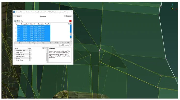
- Import the given cyber truck model and geometry check is performed to see the geometry error like single cons, holes, etc. It has lots of single cons and other error. All of the single cons can be also viewed using wireframe and viewing options.
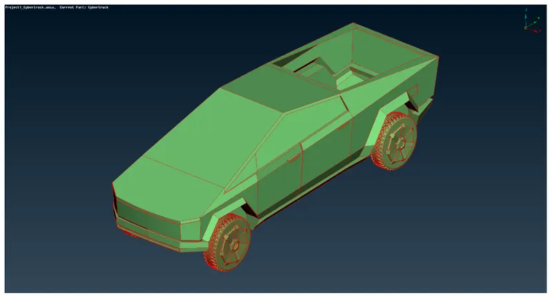
2. Perform the face topo cleanup as the model have only single cons. Look into the wireframe to identify the area where topo cleanup is required.
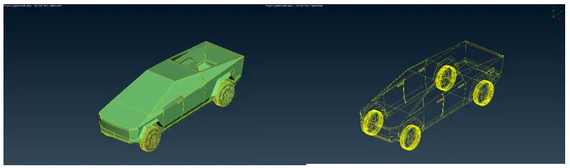
3. As the model is symmetric we can split the model in half with the help of the plane cut option. Click on the single plane cut option in the faces and select two points from the center of the car and select the faces which need to be cut and click the middle mouse button. The provided model has been split into two.
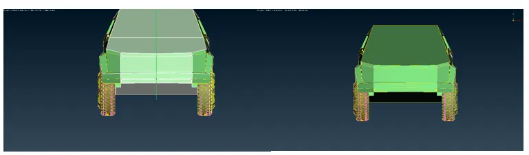
4. Delete the half right of the model by carefully selecting the faces.
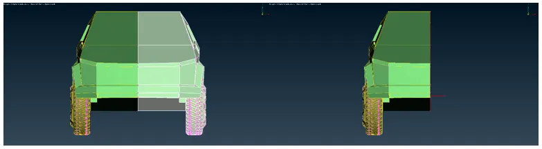
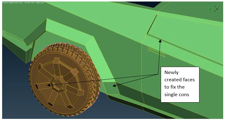
5. Let’s start fixing the single cons. There is a single con present near the side window, using the new face option create a new face. Following a similar procedure, create a face in the rear wheel cover and in the tire.
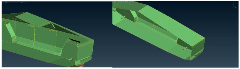
6. Trunk face cover missing on the backside of the car. Create it by using the new face option
7. There is some glitching present between the wheel shaft and body as shown in the figure. Delete the overlapping surface of the body.
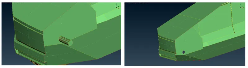
8. Using the project con option, project the single cons of the shaft from the body to shaft of the tire, then delete the extra surface of the tire shaft which is protruding inside the body. use the face topo option to connect the wheel shaft to the body.

9. Now do the geometrical check to resolve any left out errors, try fixing the left out error, make sure the single con error should be present only in half of the body.
10. After finishing all the cleanup and checking for all the errors in the geometry check, PID need to be assign to different surfaces as shown in the figure.
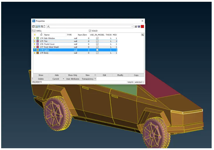
11. After defining the PIDs, let's define the target length for each of the PID’s, which are body – 5mm, tyres, lights, trunk cover, window, windshield – 3mm. Minimum and maximum target lengths will be defined according to the minimum surface edge measurement.
12. Before doing the mesh, let’s try to reduce edges whose length is less than the minimum target length, measure different edge lengths of the body, and try reducing the edge using the cut option. Similarly, do it for other parts as well
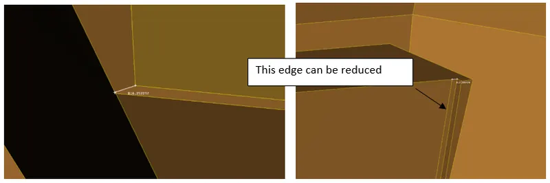 13. After deleting all the surfaces which are forming CONS less the target length, we can proceed with the surface meshing. Let’s start with the part which is not directly connected. Starting with the front windshield. In a quality, criteria specify the minimum length as 1 and maximum length as 5 mm. In meshing, parameter specify target length as 3 mm, minimum length as 1mm, and maximum length as 5 mm. Define perimeter and macros with a length of 3 mm. Then with the help of spot mesh generate the surface mesh.
14. Similarly mesh tires (min length 0.1 and max length 5) and lights with 3mm target length, mini (length 1 mm and max length 5 mm).
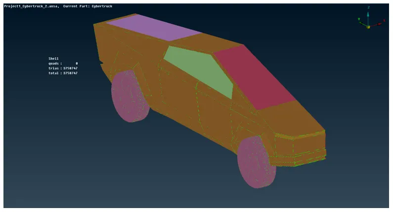 15. For body, define the target length as 5 mm, min length 1 mm and max length 8 mm. While defining the perimeter deselect the edge which is connected to other PIDs.
16. After resolving all of the quality issues, it’s time to copy the half model to another side, so that the full model of the truck can be obtained. Under the transform option, click on copy and select all the entities except the logo, then click the middle mouse button. In the popup window of copy entity, select mirror 3 points plane and select three points YZ plane, and click ok. It will reflect half of the model and after verifying everything, click on the finish.
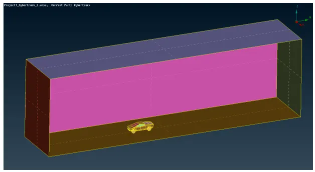
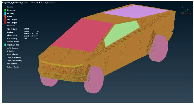 17. Now to construct a wind tunnel around our car, we have to measure the length of the car (X) which is 5740 mm. so the front end of the wind tunnel is 4X distance (22960mm) from the front end of the car, the back end of the wind tunnel is 6X (34440mm) from the rear point of the car, Top end of the wind tunnel is 3X (17220 mm) distance from the top point of the car and the side of the wind tunnel is X distance (5740 mm) from the side of the car.
18. With the use of the measure, relative points, create curves and coon surface, create the wind tunnel as shown below.
 19. Now switch to mesh mode and define perimeter and macros of 100 mm for the top surface and 20 mm for the bottom surface of the wind tunnel.
20. Now for the vertical cons, the mesh length is going to vary from 20 mm to 100 mm, which can be created using the spacing option. Set biasing to geometric, factor to 1.1, dmin to 20, and dmax to 100.
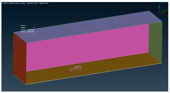
21. Now start meshing bottom surface, define target length of 20mm, quality criteria as min length 15 and max length of 25 mm, then generate the mesh using spot mesh
22. For top surface, define target length of 100mm, quality criteria as min length 80 and max length of 120 mm, then generate the mesh using spot mesh.
23. Now generated the mesh for other surfaces one by one using spot mesh directly as length is already defined.
24. After finishing, all the surface mesh for the tunnel, switch to the volume mesh tab and click define. With the whole domain selected click ok. Ansa will automatically define the closed volume, select the one between the tunnel and the car, delete the rest of the volume. Your model is ready to create the tetra mesh.
Learnings :
- Different options are explored in-depth to remove single cons in the TOPO clean-up tab.
- Learned how to do the half model cleanup instead of the full model which saves time tremendously.
- For large assembly, it’s better to do component-wise cleanup and meshing one by one.
- Learned to do meshing with quality criteria in mind.
- Before doing meshing it’s better to remove small length cons not satisfying minimum length criteria.
- For a component that is attached to some other component having a different target length, it is preferable to do the meshing at last for that component.
- Learned how to see the fail element using the hidden mode and explored different options to fix the issue like move grid, smooth mesh, reconstruct, etc.
- Explored the option called spacing in mesh mode which allows creating a grid of varying length.
- Learned how to convert half model to full model using the symmetry option.
- Learned how to generate the volume mesh from 2D mesh.
Result and conclusions:
- Given Tesla Cyber Truck car model is cut to half to save time
- Different PIDs has been meshed with different quality criteria and mesh target length (given). PID’s which is not connected to each other adjacently should have meshed first.
- After doing surface mesh, the Full model is created by copying the half model.
- A standard wind tunnel is generated according to car dimensions.
- The spacing tool is used to gradually grow mesh length from the road to the top of the wind tunnel.