Week 3 Challenge : CFD meshing on Turbocharger
Aim:CFD meshing on Turbocharger
Objective:
- check for the geometrical errors to make appropriate volumes. Create and assign PIDs as shown in the video. Perform surface mesh with the given target lengths as per PIDs.
- Blade stage-1 = 1 mm
- Blade stage-2 = 1 mm
- Impeller = 2 mm
- Shaft rotor = 1 mm
- Turbo casing = 5 mm
- Compressor casing = 5 mm
- Inlet casing cover = 5 mm
- Perform Volumetric mesh for the required volumes as shown in the videos.
THEORY:
surface meshing:A surface mesh or "shell mesh" represents model parts that are relatively two-dimensional, such as sheet metal or a hollow plastic cowl or case. In addition, surface meshes placed on the outer faces of solid objects are used as a baseline mapping point when creating more complex 3D meshes (the quality of a 3D mesh largely depends on the quality of the 2D mesh from which it is generated).
Three-noded trias, four-noded quads, six-noded trias, and eight-noded quads are some of the types of elemenst
Valume meshing:Volumetric meshes are a polygonal representation of the interior volume of an object. Unlike polygon meshes which represent only the surface as polygons, volumetric meshes also discretize the interior structure of the object.
One application of volumetric meshes is in finite element analysis, which may use regular or irregular volumetric meshes to compute internal stresses and forces in an object throughout the entire volume of the object.
Procedure:
steps whic we have to fallow to create valumetric mesh shown below
- Geometry import and cheak
- Setting up Properties using set PID command
- Geometry clean up(deleting the unnecessary drawing)
- Meshing
1.surface meshing
2.valume meshing
- measuring the lenght
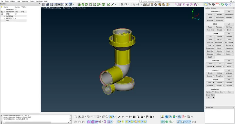
Geometry import and cheak: First steps is to import the geometry into the ANSA by going to FILE>OPEN>IMPORT as shown below.
cheaking the geometry: for geometry cheak we have to go to TOOLS>CHEAK>GEOMETRY as shown below
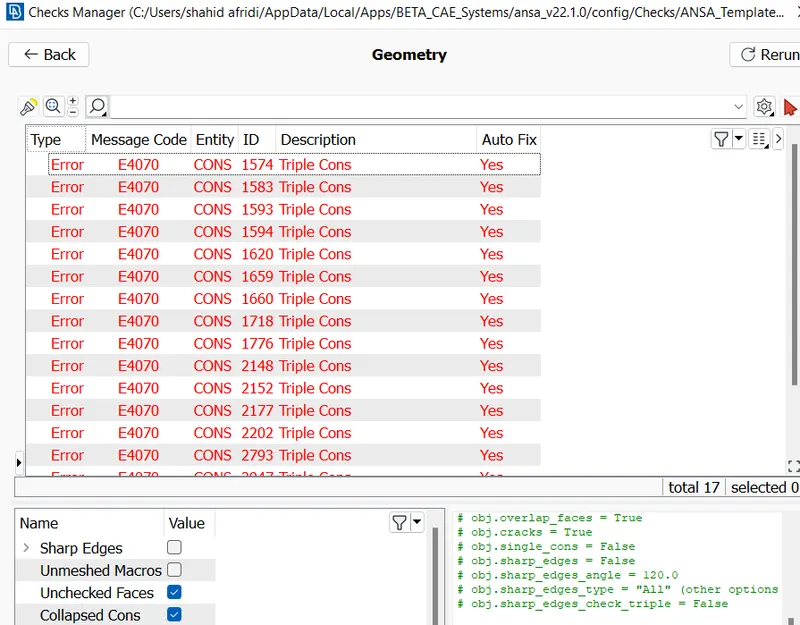
as we can see above our geometry have many overlaping region and alse it have some singel cones and double cones.which has to be define before starting the mesh process
Geometry clean up(deleting the unnecessary drawing):here we have to clean the geometry by removing the any extra cones,face and hotpoints.
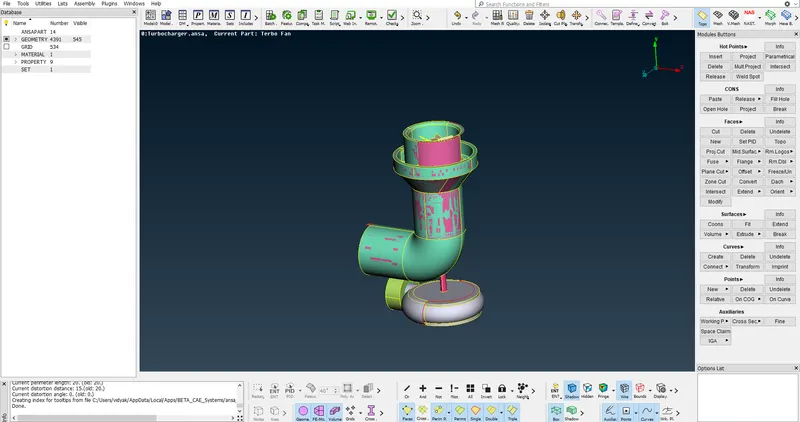
- We can see the purple glitching on the green surface in the below figure.This means that there are 2 surfaces overlapped on each other at that location that has to delete by going TOPO>DELETE AS SHOWN BELOW
- Start with fill the surface and clearing the single cons by creating surface where ever required.
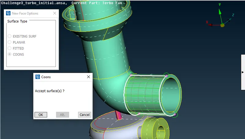
- Certain areas created by using the new option under faces don't satisfy the surface we require, therefore, certain hotpoints are projected so that small surfaces can be created and later can be joined and get the required geometry.
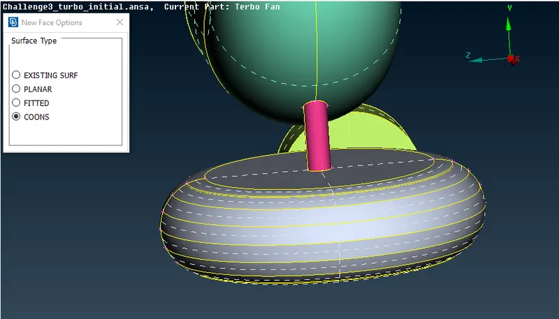
- like that we had many errors in our geometry which we have fix by using respective tools and after cleaning the geometry our geometry look like below
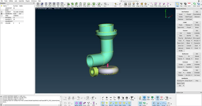
Setting up Properties using set PID command:for setting the pid first we have turn on the crossedge in order to select the face for giving the properties
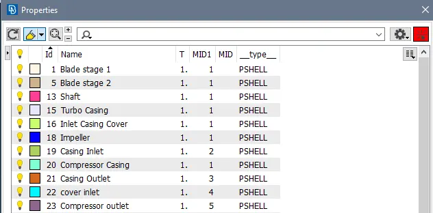
after that we have to go to PROPERTY then we have to creat the new labels and then we have to give naming to the facing as shown below
- blade stage 1
- blade stage 2
- shaft
- turbo casing
- inlet casing cover
- impeller
- casing inlet
- compresser casing
- casing outlet
- cover inlet
- compresser outlet
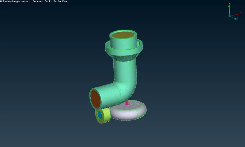
Meshing:After cleaning the geometry we have to create the mesh by going to MESH>LENGTH>PARAMETRIC+MACROS after this setup mesh element by going on MESH PARAMETER>TARGET LENGTH>ELEMENT TYPE(TRIO)>SPOT MESH as shown below
- meshing compressor casing,casing outlet,inlet with 5mm lenght as shown below:
- now we have to mesh the blades with 1 mm lenght as shown below
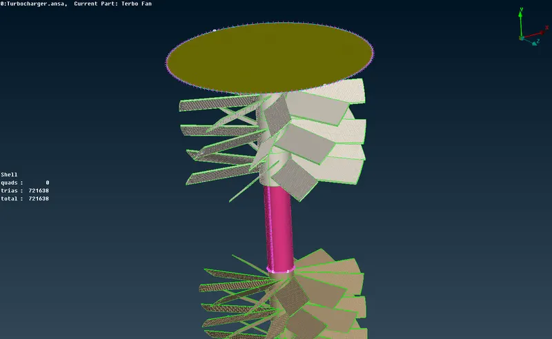
- after that we have to do mesh for impeller with 2mm lengh as shown below
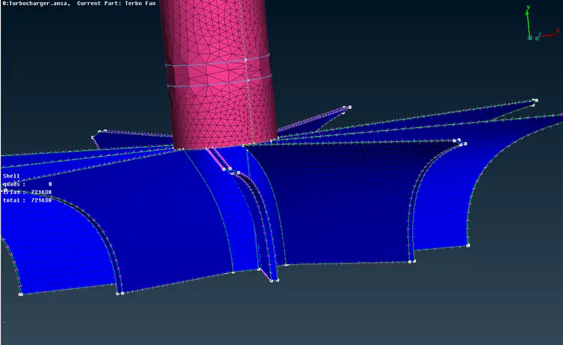
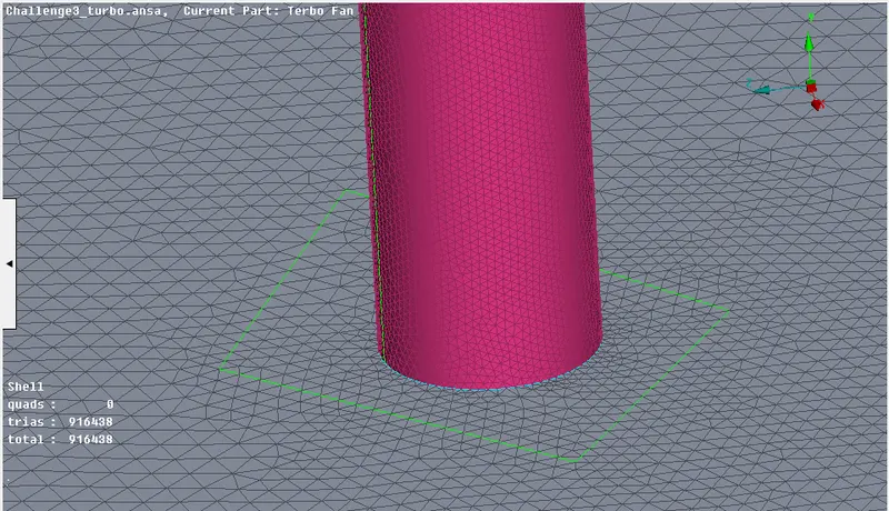
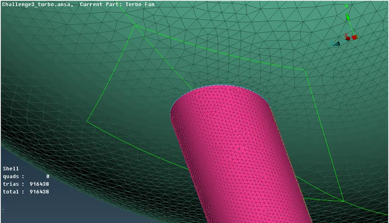
- After the mesh is generated, we can create a boundary of the varrying mesh length and maintain a constant mesh length on the other side of the boundary as shown below
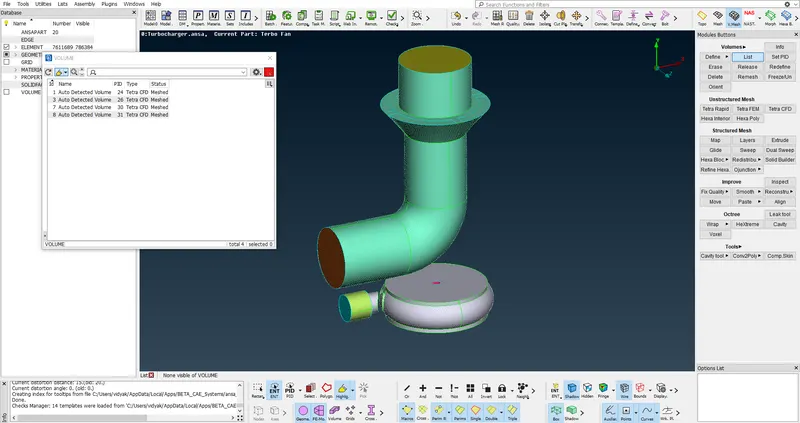
Volume mesh:For generating a volumetric mesh we go to the right side menu and in theVALUME > DEFINE > USE THE ENTAIRE DATABASE press ok.
- It should detect a total of 8 volumes. In those 8 volumes we need only 4 volumes. These volumes are the thickness of all the components AS SHOWN BELOW TABEL
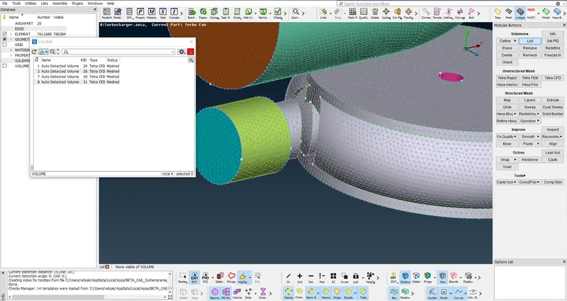
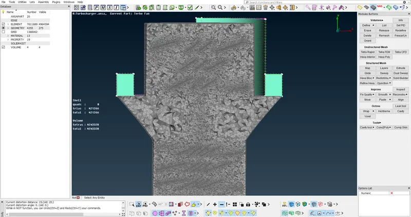
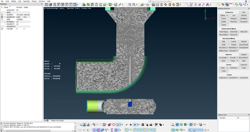
- Once the required volumes are extracted we right click on these volumes select remesh and select tetra cfd. This generates 6728983 volumes all tets as shown.
CONCLUSION:
- Realizes the volume mesh of the turbocharger model.
- Different mesh length sizes tend to cause errors in the contact areas of two different mesh length areas, so you can specify a mesh area to avoid mesh deletion
- Volume meshes can only be achieved after the surface mesh has been successfully created. Otherwise, the geometry can cause serious errors in the volume mesh.
- Duplicate faces can be removed using the universal delete option.
- You can use various tools such as Cons Project, Topo, Release, and Fine Tools to organize your geometry while removing and editing unwanted single and triple shortcomings.
- The correct geometric cleanup and surface mesh must be used for the volume mesh to be successful.