Week 3 Challenge : CFD meshing on Turbocharger
OBJECTIVE:-
- To perform Volumetric mesh on given model using ANSA and also check geometrical errors and perform Topology cleanup accordingly.
- To Set three different target length as 1mm, 2 mm and 5 mm ( accordingly) and mesh the model for each PID's and element type must be Tria.
- Blade stage-1 = 1 mm
- Blade stage-2 = 1 mm
- Impeller = 2 mm
- Shaft rotor = 1 mm
- Turbo casing = 5 mm
- Compressor casing = 5 mm
- Inlet casing cover = 5 mm
Make a detailed report on surface meshing & Volume meshing process.
Tools Used:-
1. Checks Manager
2. Faces
3. PID (properties)
4. Perimeter and Macros
5. Mesh Generation > Spot Mesh
6. Volume Mesh > Define > Remesh >
Procedure:-
- Import the Geometry.
- Geometry Clean Up
- Assigning the PID's
- Assigning the Perimeter & Macros
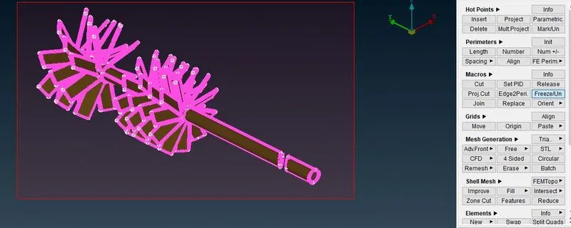
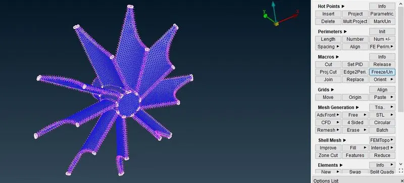
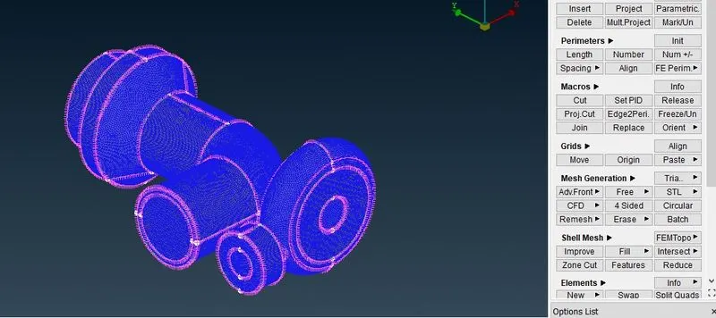
- Selection of Spot Mesh from Mesh Generation in mesh Module and freezing each PID.
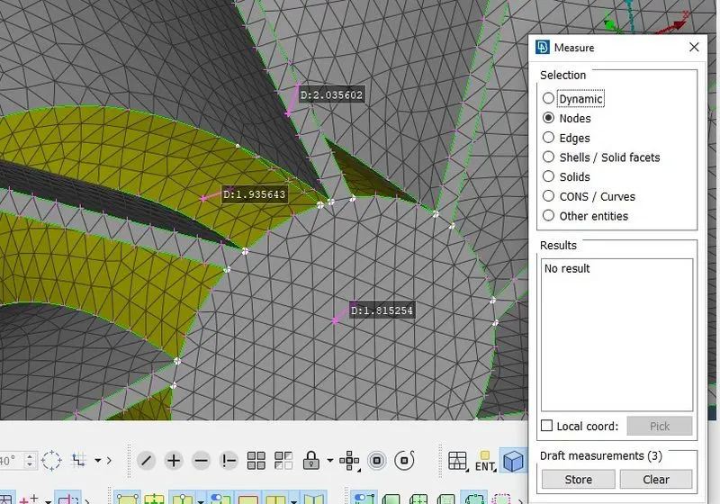
- Measure the Mesh size
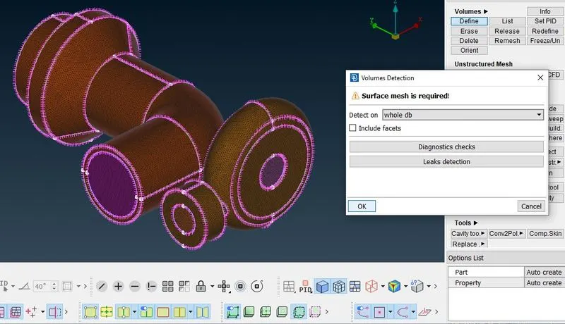
- create a volumetric Mesh
- Import the Geometry:-
Import the geometry using open in file menu from the Specified Path.
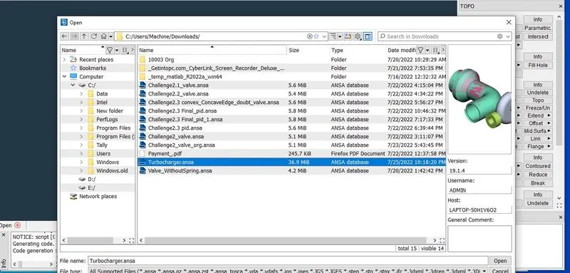
2. Geometry Clean Up
Geometry Checkup is done to make single cons to faces by creating new face or using fill hole. And remove extra Hot points and overlaping Surfaces to prevent irregularities in shape of our geometry.
This step is done to check if there are any errors in the model like unclosed faces, Superimposing faces, etc.
upper Toolbar→
Checks →geometry→Visible→execute→check for the green tick beside geometry→
close the window
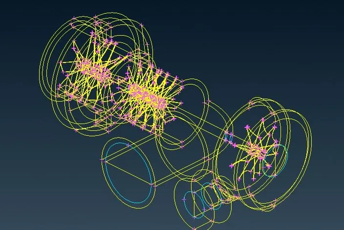
Before Geometry Clean Up
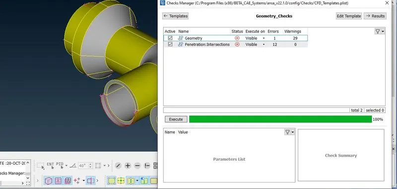
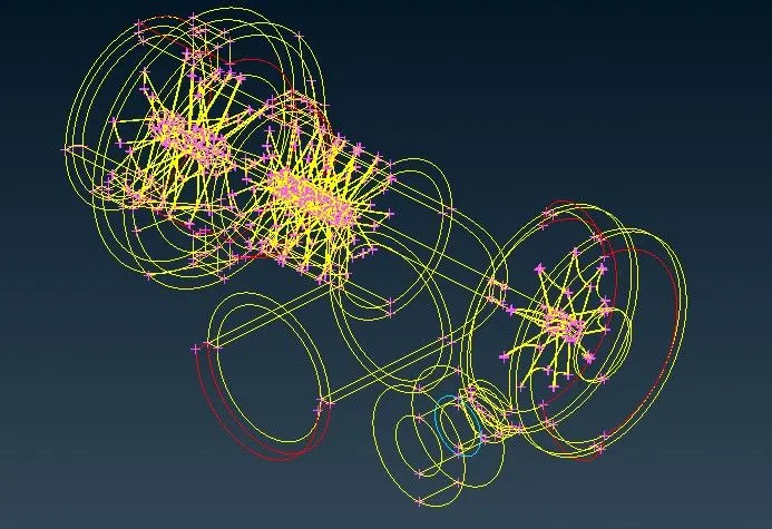
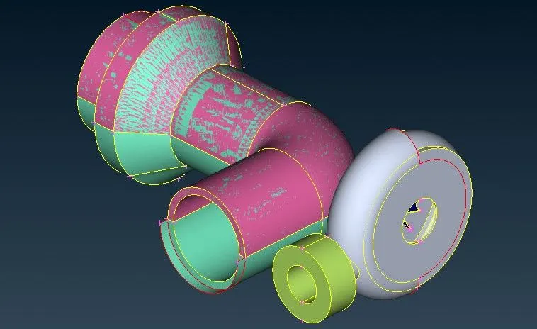
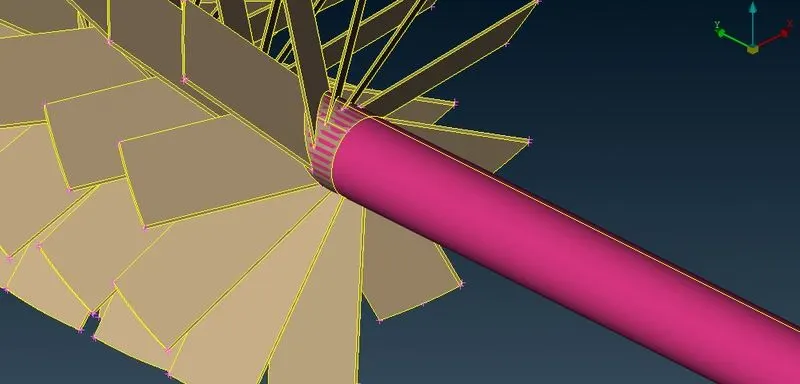
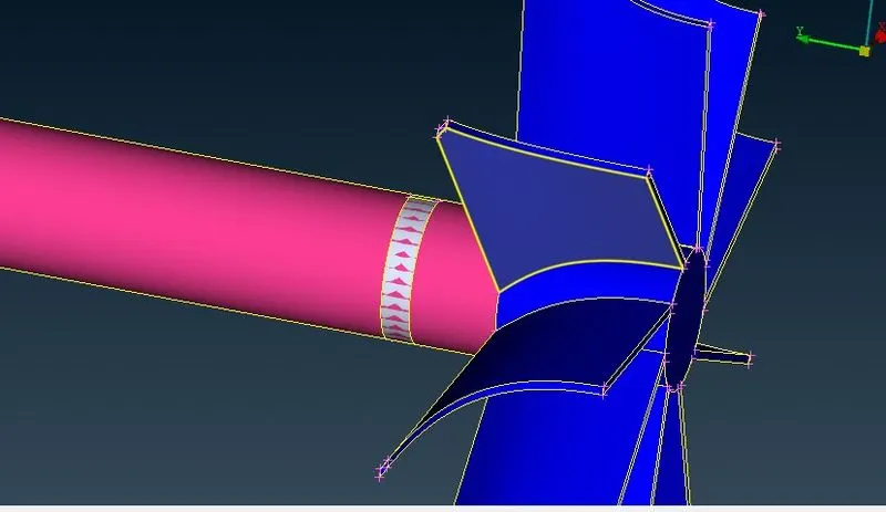
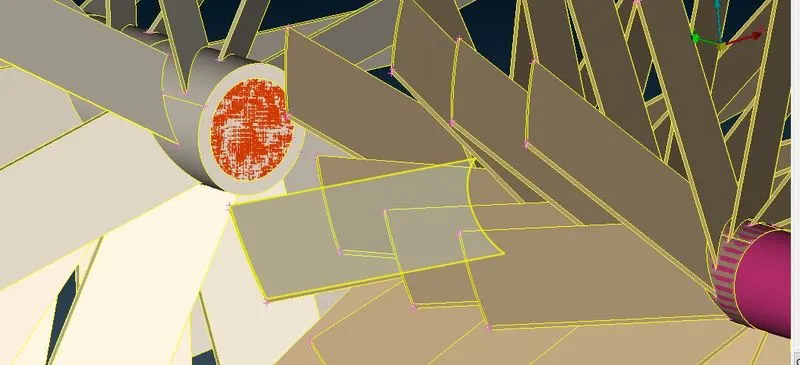
In Geometry Single cons (red) needs to be converted to face, the intersected parts needs to be cleaned and superimbosed faces should be deleted.
After Geometry Clean Up:-
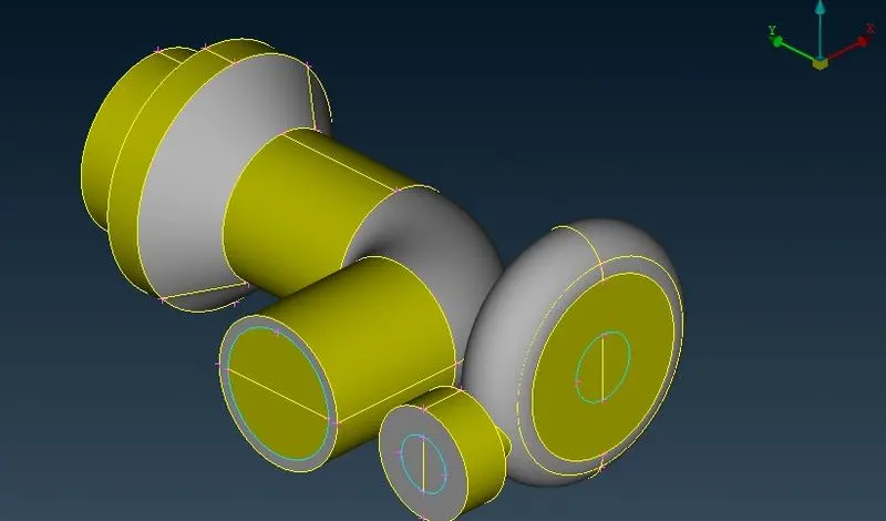
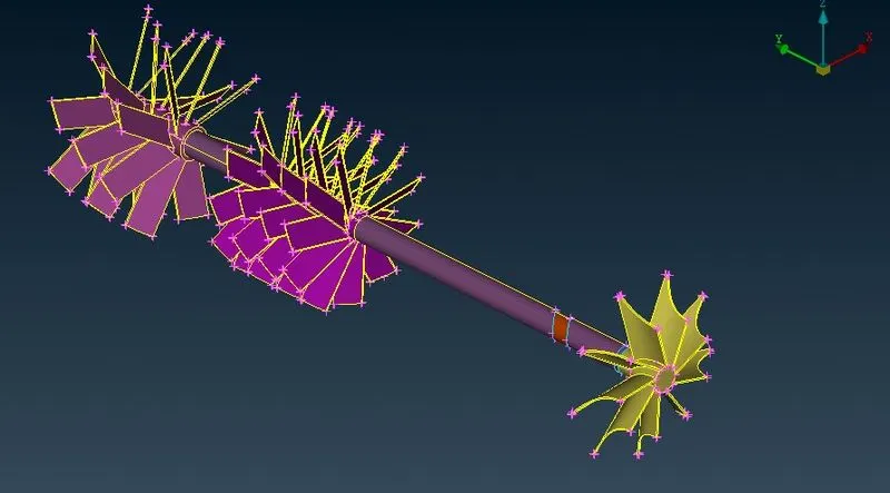
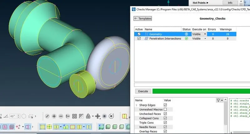
In geometry there are some warning as these are not errors we can neglect them,Or we resolve them one by one, here are warnings of triple cons however they are required for water tight geometry.
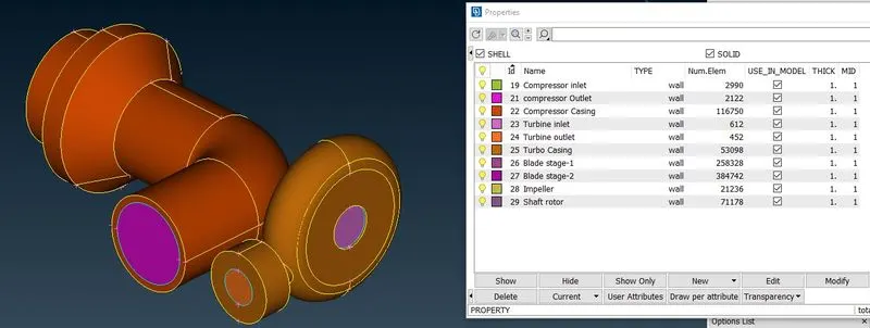
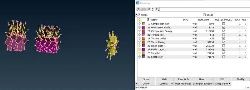
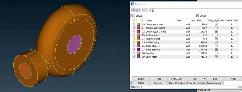
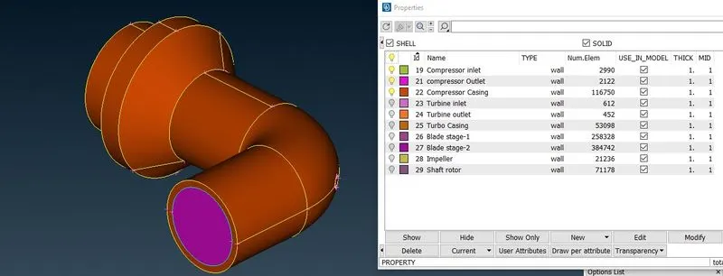
- Assigning the PID's:-
Upper toolbar > Mesh module >
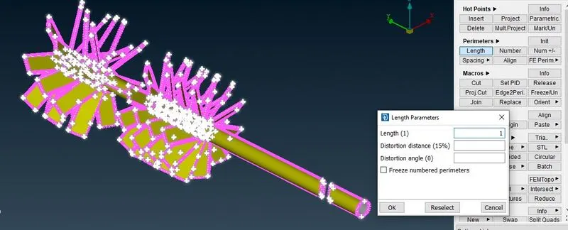
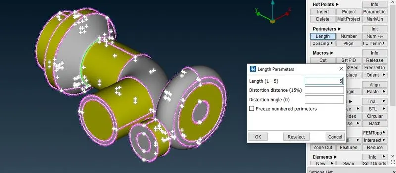
Perimeters > Length >
Select Perimeters >select the whole entity(Same Mesh Size of every PID) or each PID to which we want Mesh>
- Assigning the Perimeter & Macros
Upper toolbar > Mesh module >
Perimeters > Length >
Select Perimeters >select the whole entity(Same Mesh Size of every PID) or each PID to which we want Mesh>
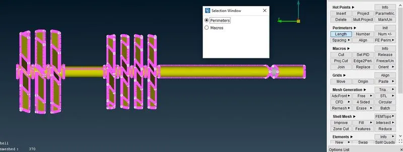
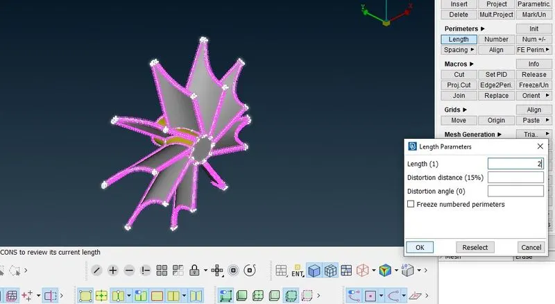
Target Length of rotor Shaft,blade stage -1&2 is 1mm
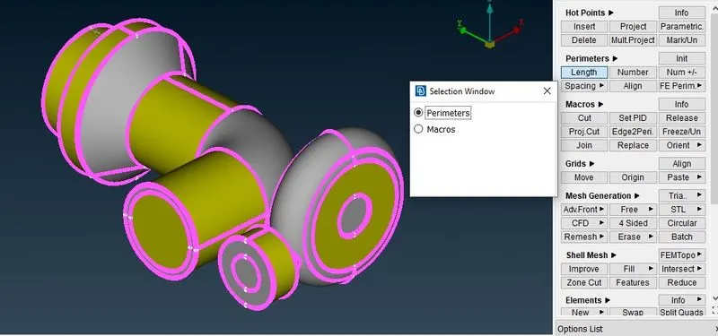
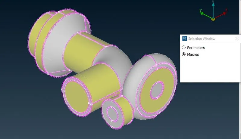
Target Length of Compressor casing and turbine casing is 5mm.
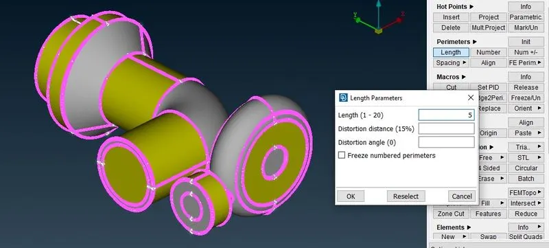
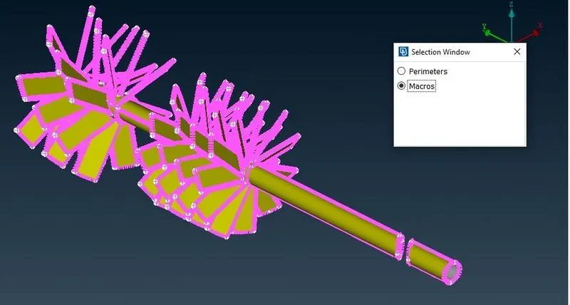
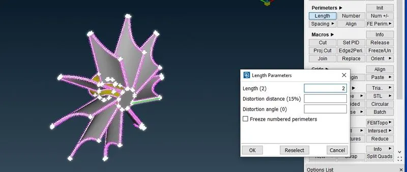
Similarly In Macros.
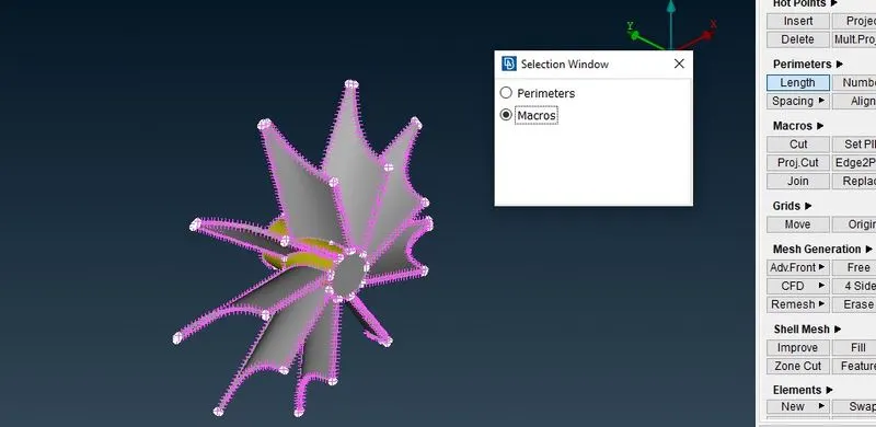
Upper toolbar>Mesh module >
Perimeters >Length>
Select Macros >select the whole entity to which we want Mesh>
5. Selection of Spot Mesh from Mesh Generation in mesh Module and freezing each PID.
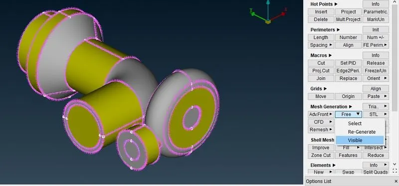
Upper Toolbar > Mesh module > Mesh Generation > Spot Mesh > visible
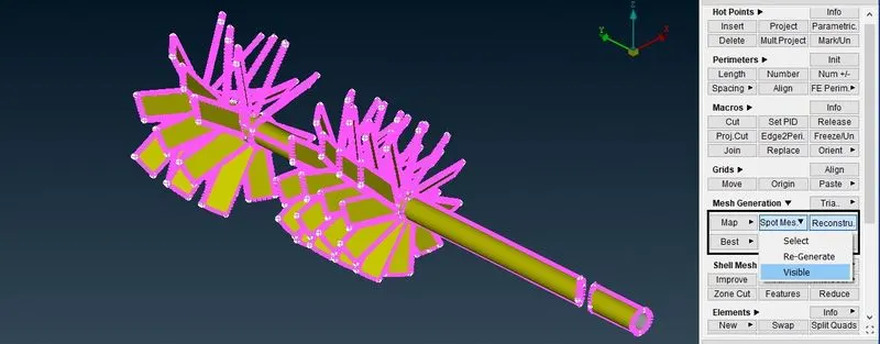
Freeze Shaft and blades.
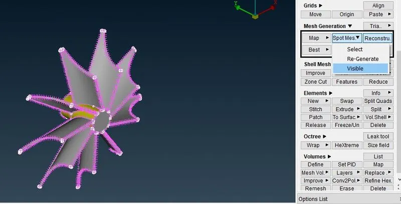
Freezing Impeller
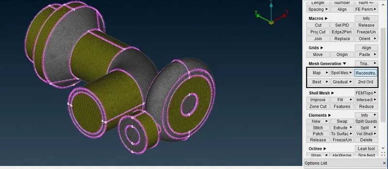
Freezing Turbine and compressor Body
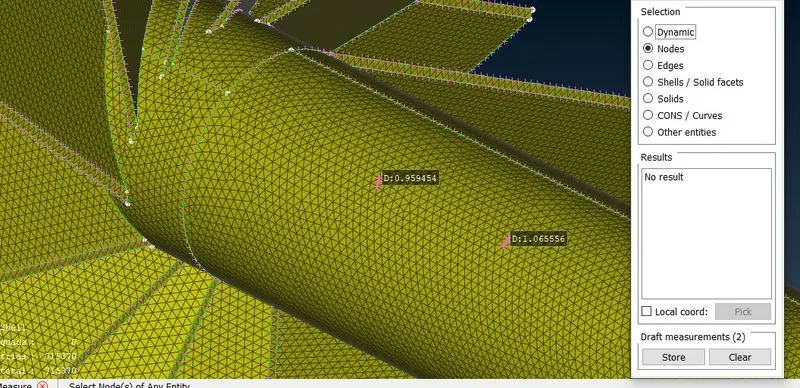
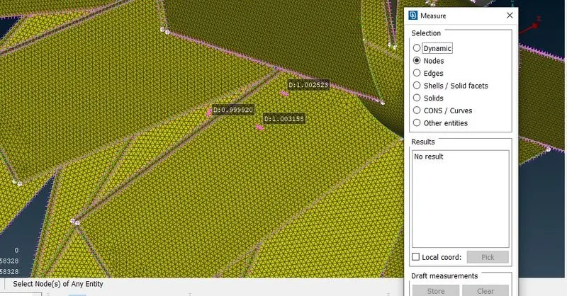
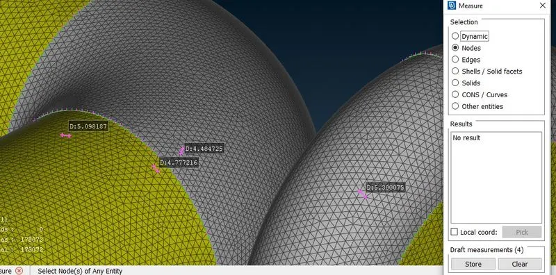
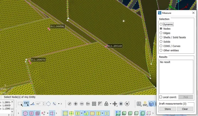
6. Measure the Mesh size
7. create a volumetric Mesh
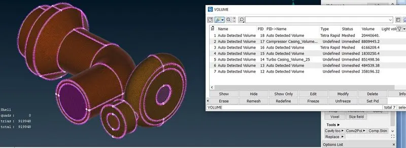
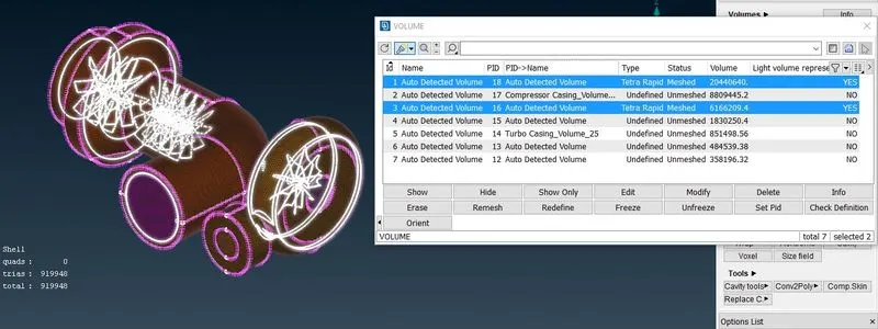
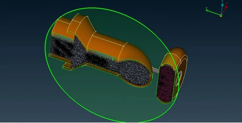
Voume 1 and 3 are our fluid voumes in compressor and turbine, and is shown below.
CONCLUSION:-
Volumetric mesh on given model is performed , geometrical errors is checked & Topology cleanup is done accordingly. Volumetric Model is generated according to the given element length according to conditions.