Week 3 Challenge : CFD meshing on Turbocharger
Aim:
For the given model of a turbocharger, check for the geometrical errors to make appropriate volumes. Create and assign PIDs accordingly. Create surface mesh and use that to create a volumetric mesh.
Objective:
1. Perform surface mesh with the given target lengths as per PIDs.
Blade stage-1 = 1 mm
Blade stage-2 = 1 mm
Impeller = 2 mm
Shaft rotor = 1 mm
Turbo casing = 5 mm
Compressor casing = 5 mm
Inlet casing cover = 5 mm
2. Perform Volumetric mesh for the required volumes as shown in the videos.
3. Write a detailed report on your surface meshing & Volume meshing process
Turbocharger:
A turbocharger is a device fitted to a vehicle’s engine that is designed to improve the overall efficiency and increase performance. A turbocharger, colloquially known as a turbo, is a turbine-driven forced induction device that increases an internal combustion engine's efficiency and power output by forcing extra compressed air into the combustion chamber. Turbocharger performance influences all-important engine parameters, such as fuel economy, power, and emissions.
A turbocharger consists of a compressor wheel and exhaust gas turbine wheel coupled together by a solid shaft and that is used to boost the intake air pressure of an internal combustion engine. The exhaust gas turbine extracts energy from the exhaust gas and uses it to drive the compressor and overcome friction.
A turbo is made up of two halves joined together by a shaft. On one side, hot exhaust gasses spin the turbine that is connected to another turbine which sucks air in and compresses it into the engine. This compression is what gives the engine the extra power and efficiency because as more air can go into the combustion chamber, more fuel can be added for more power.
In most automotive-type applications, both the compressor and turbine wheel are of the radial flow type. Some applications, such as medium and low-speed diesel engines, can use an axial flow turbine wheel instead of a radial flow turbine.
Procedure:
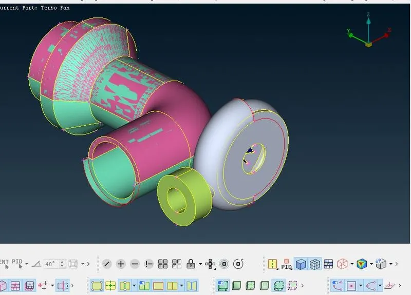
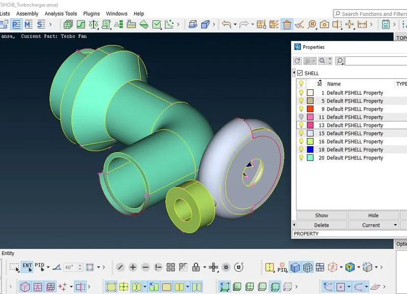
After uploading geometry into ANSA, set geometry to PID mode. This image is our original geometry, as we can observe there are mixed green and pink colors on the surface, these are overlapped surfaces. our geometry is filled with overlapping, intersecting and extended surfaces, all these surface requires to be removed by deleting them. There are multiple single cons present in geometry and some unnecessary double cons.
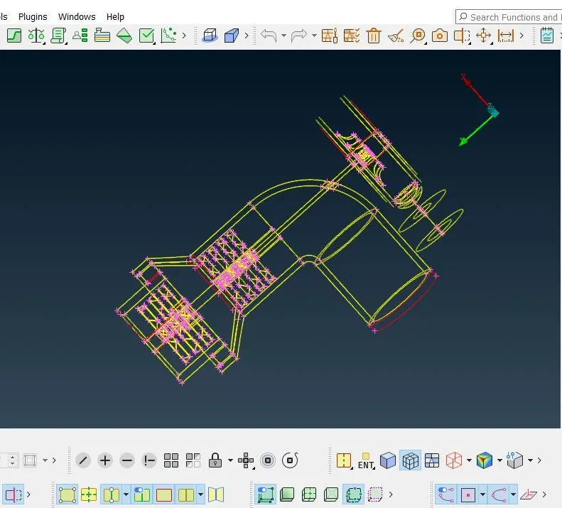
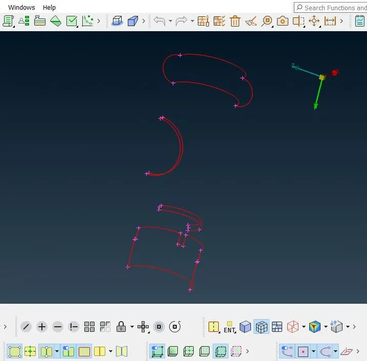
After putting geometry into wireframe mode, we can see our single, double, and triple cons. All single cons are due to extended, intersecting, or absent surfaces. All of them require to be fixed.
Geometry cleanup:
Overlapped Surface
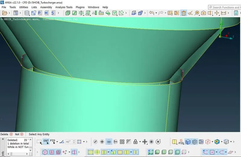
In our original file, we have seen mixed colors on the surface due to because there was overlapped surface. This time we have to remove the overlapped surface from the original surface using not a tool in ANSA so that we can see the pink color surface which was extra and needs to be deleted. Choose a pink surface and delete them. When we examined the complete geometry we observed a small overlapped surface inside the geometry, on the shaft and rotor which we will delete by following the procedure discussed above.
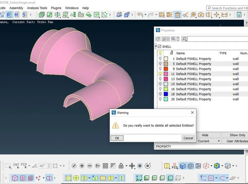
After the deletion of the overlapped surface.
Intersected surface
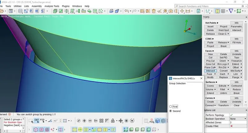
The top of the turbocharger has some intersecting surfaces which we can see in the second image(highlighted in purple). Use the intersecting tool from 'TOPO' mode and select the first intersecting surface and then the second intersecting surface and do a middle click. This will separate intersected surfaces from geometry.
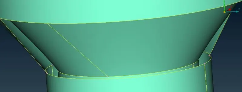
The extended surface is separated from the geometry and we will delete both of them using the delete option. We can see dash lines on extended surfaces that were absent before using the intersecting tool. now select the surface by clicking on dashed lines and delete them.
Single and Triple Cons
The RED color line represents single and blue color double cons. single cons appear mostly due to missing surface or separated cons.
We will follow two steps to remove single cons
Create missing surfaces by using tools from the face tools option.
Join two single cons separated by a small distance using the paste option. If there is a con on one surface and no cons on other surfaces, in such a case use the project option to project the con of one surface on the other surface and then join them together using the paste option.
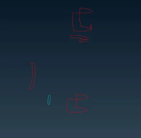
In the below geometry we cannot directly use the face tool to create a new surface as the surface made was not acceptable, so we will try splitting the surface by creating hot points. Start creating 'Hot' points at shown locations and then create a small new surface using these hot points first.
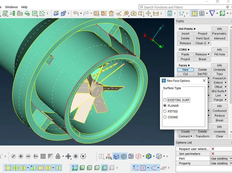
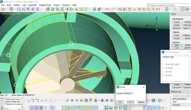
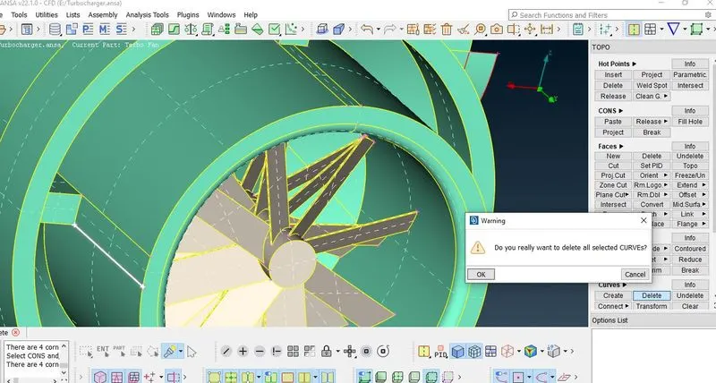
Now as we can see the missing surface is square after we created the previous surface using hot points. It is easy now to create a new surface by using the face tool as the missing surface is a simple square and not some complex geometry. Select cons and do a middle click.
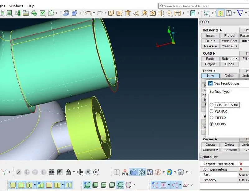
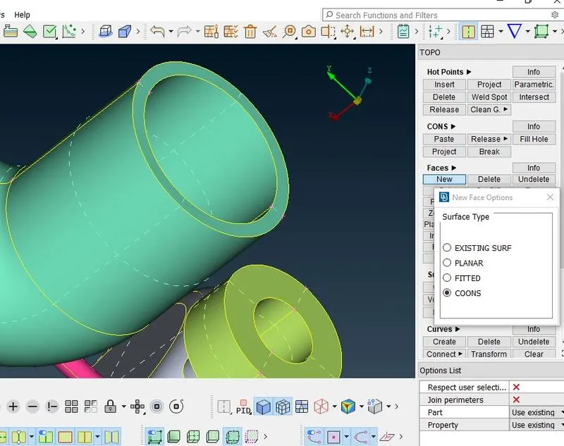
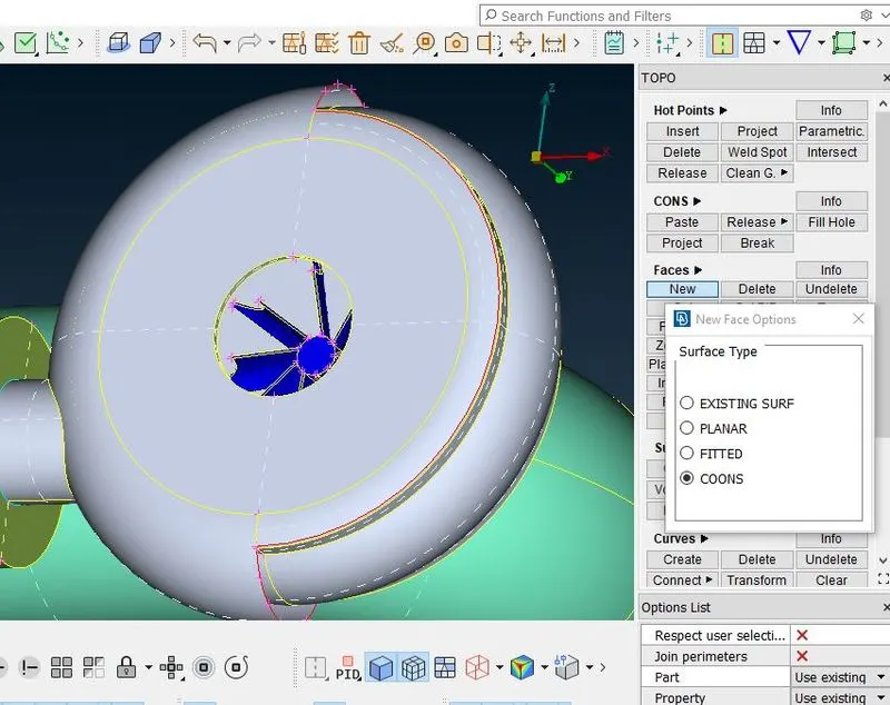
In the Impeller section, we need to create the surfaces to close the geometry of the impeller casing. we will create hot points and then try to join them using the face tool.
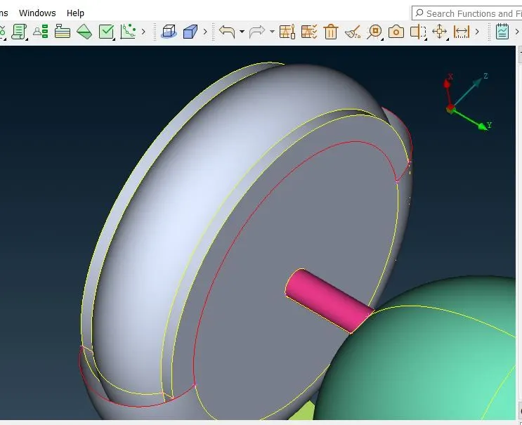
Hot points were created.
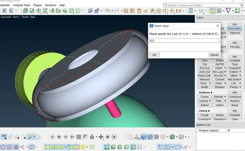
Using a face tool to create a new surface.
New surface created
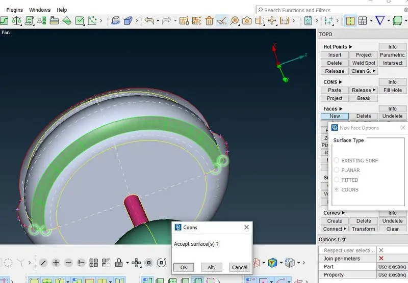
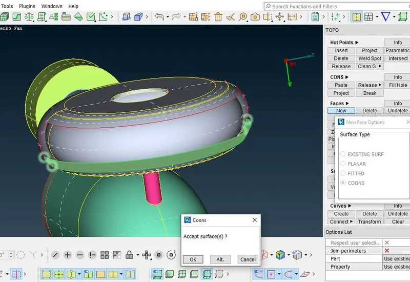
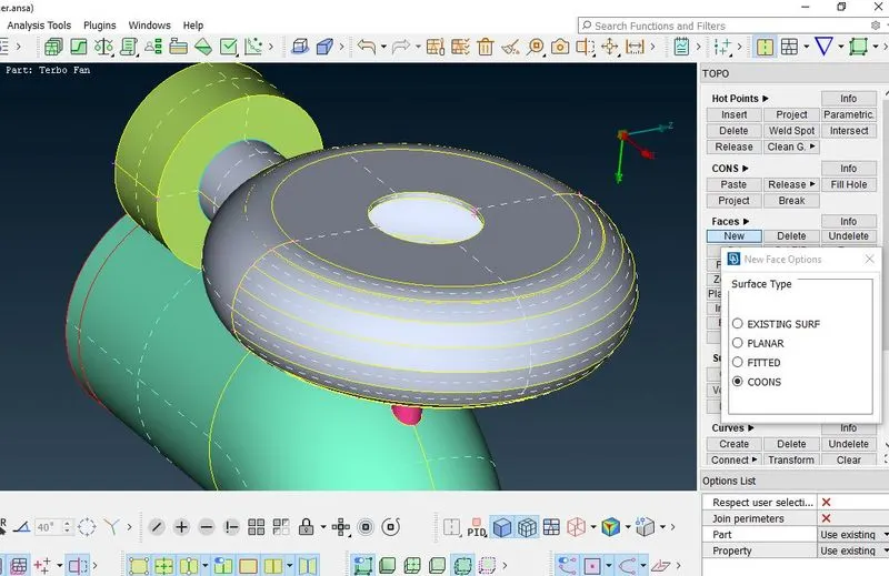
In geometry shaft should be completely hollow with no hindrance, so we will remove all surfaces to make the shaft hollow so that it would be considered one surface.
The cleaning procedure is continued by the following procedure:-
Inside the shaft section, the extra surface in the shaft has to be deleted so that we can see through the entire length of the shaft. The extra surface would create a problem during meshing. And while deleting the surface some extra single cons are created which are to be removed or rectified by the Topo tool by doing the entity selection of the single cons.
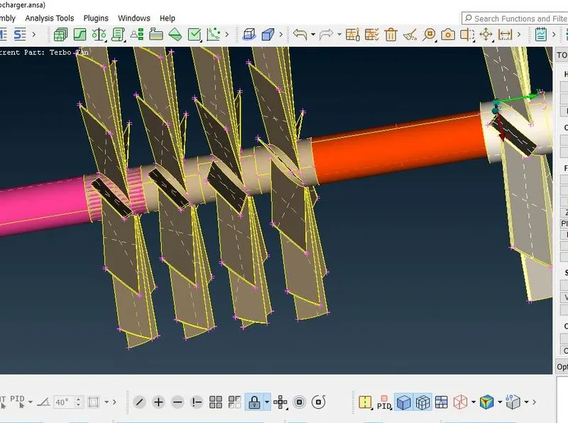
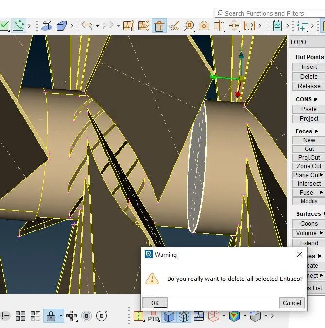
Once the single cons are solved, we can focus now on solving for triple cons which are present in the shaft region, since we need to have a single volume that makes it easier to mesh in the later stage. Delete the overlapping surfaces to reduce them to double cons.
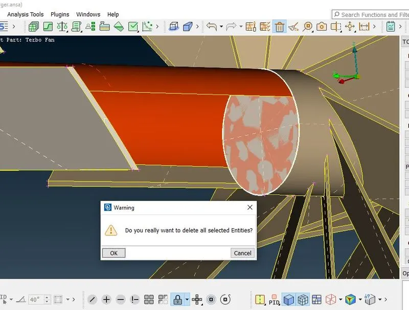
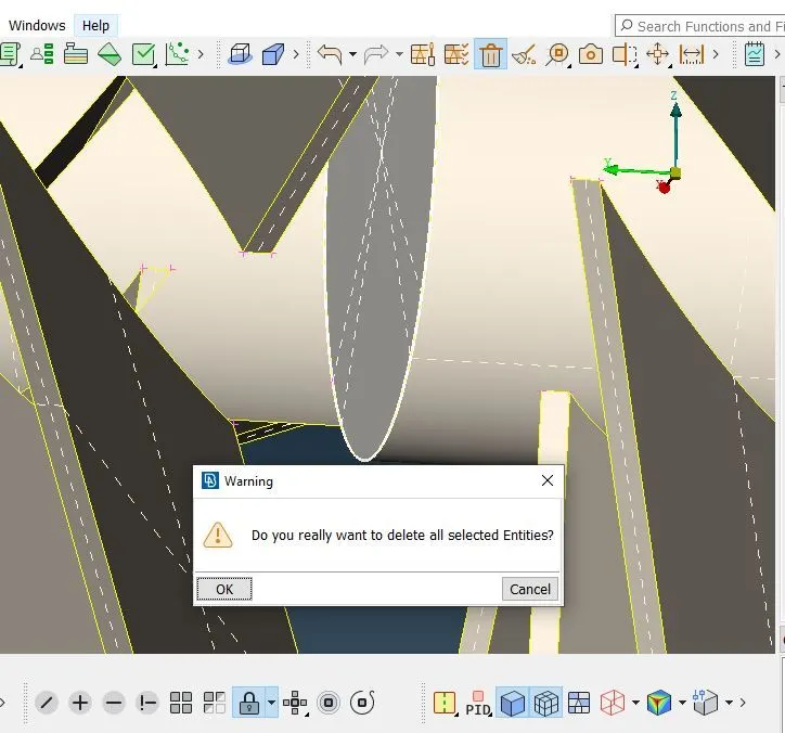
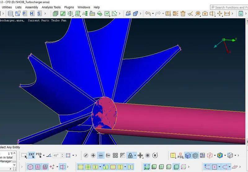
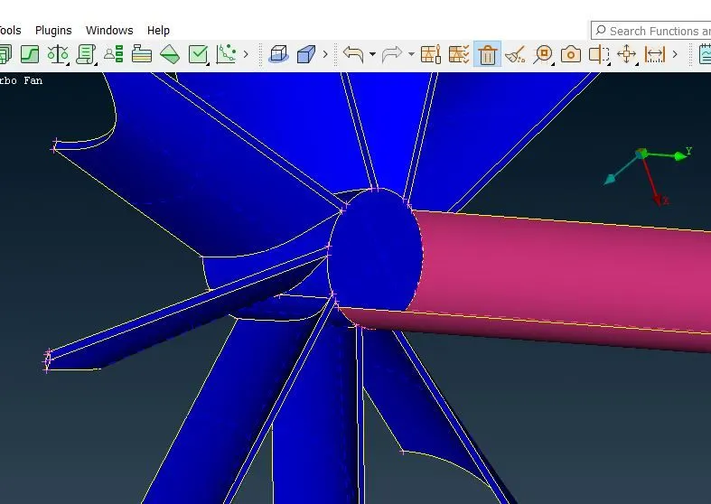
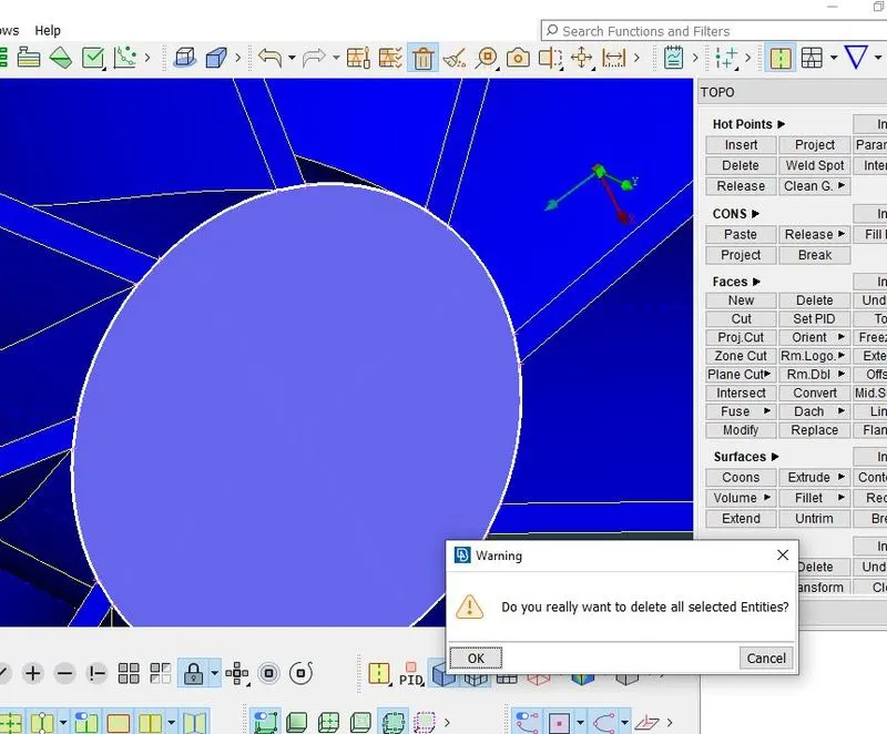
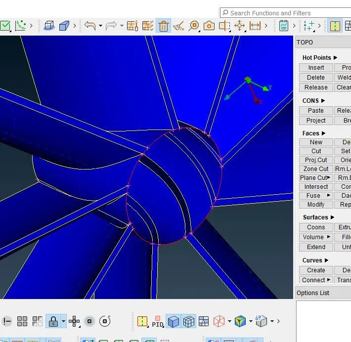
All the open surfaces need to be closed so that we can extract the fluid volume that would be useful for the CFD analysis.
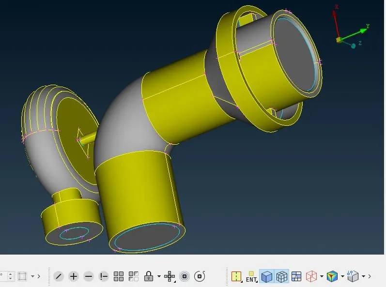
Changing PID names:
After the unnecessary triple cons are removed, we can now start naming each part by assigning them an individual PID.
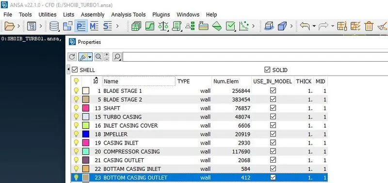
After naming them, we can now move ahead with surface meshing.
Surface meshing:
We need to mesh each component as per the given criteria in the question, therefore we need to mesh the component individually.
we have to give a different length for the different components:-
Blade stage-1 = 1 mm
Blade stage-2 = 1 mm
Impeller = 2 mm
Shaft rotor = 1 mm
Turbo casing = 5 mm
Compressor casing = 5 mm
Inlet casing cover = 5 mm
Steps to create 2D mesh
Give quality criteria of minimum and maximum mesh length for a particular mesh size. Suppose if mesh length is 5mm then we can take minimum mesh length as 3 and max as 7.
Give mesh properties, choose tria elements and specify mesh length and give min and max values for mesh length.
Choose length tool a pop-up box will appear which will ask to give perimeter and macros length.
Choose perimeter and select PID by right click and dragging the mouse to cover the whole PID or you can use entity mode. Do middle click.
Choose macros and select PID by using the PIDregion tool and then do the middle click.
Select spot mesh and select PID by using PIDregion.
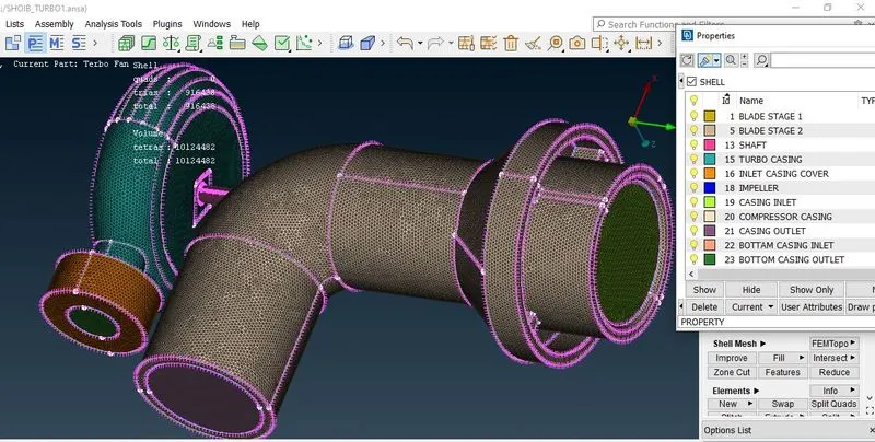
2D mesh of Casing inlet, Casing outlet, and Compressor casing:
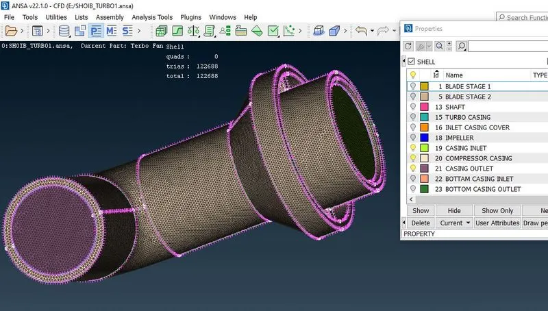
2D mesh of Impeller and Turbo casing:
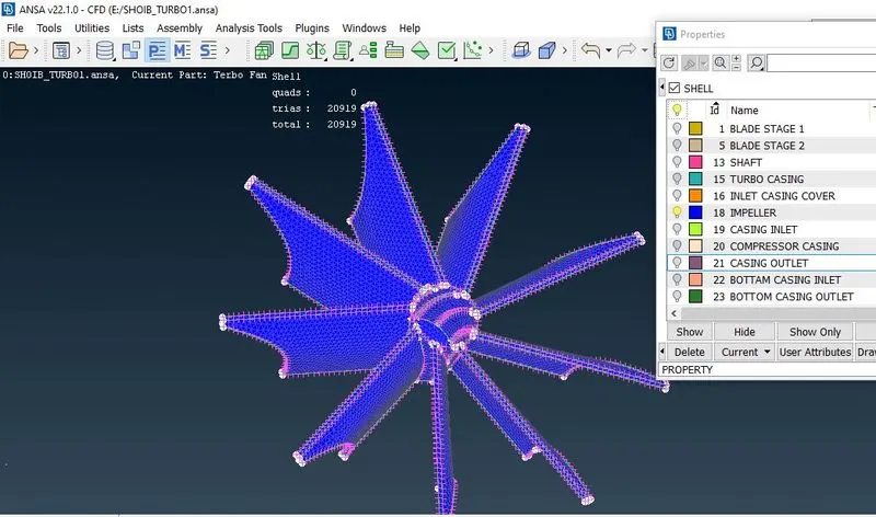
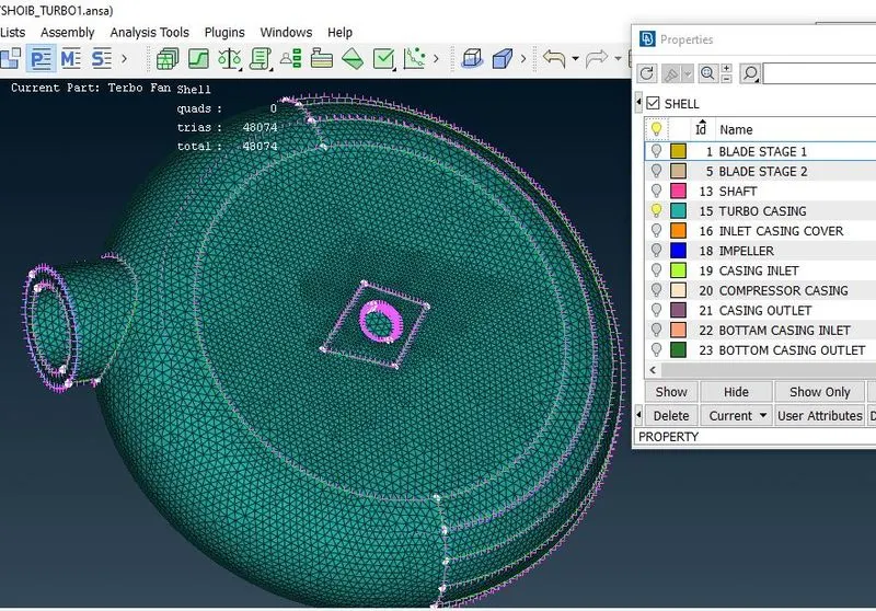
2D mesh of Shaft, Blade stage 1, and Blade stage 2:
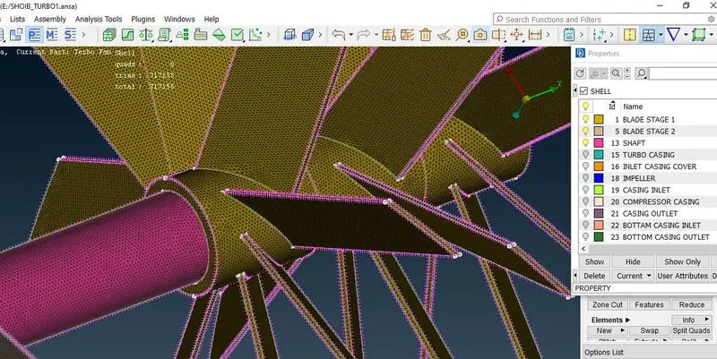
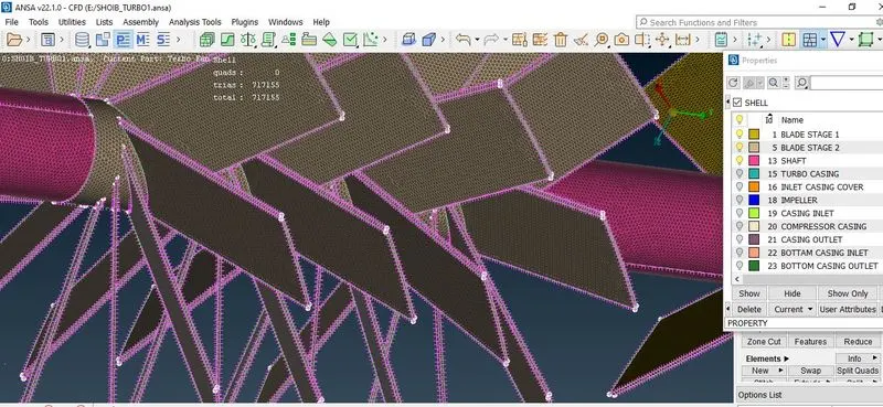
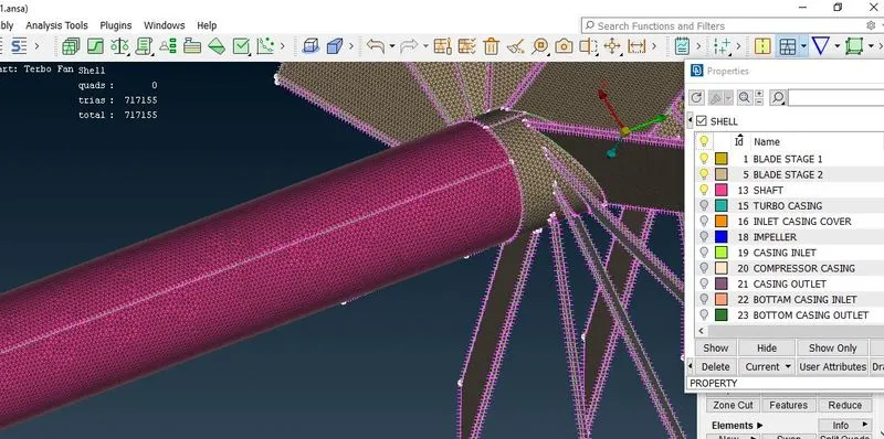
NOTE: While meshing you will come across a problem which is the disappearance of meshes from regions where 2 PIDs with different mesh lengths are joining. This happens because of mesh size domination as ANSA is confused about which mesh size to follow at transition points between two PIDs.
To cope with this problem:-
While giving macros length you will see mesh length varying in a range in which minimum length will be of one PID and maximum length will be of PID on which you are meshing. So don't give any input in macros and select the spot mesh option to mesh.
In the below picture, we can observe mesh size of the bisque color PID is changing as it approached the pink color PID. This is adjusting mesh size at the joining point of PIDs with different mesh lengths.
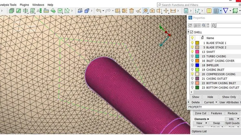
While entering the mesh length, be aware of the change in mesh length between components with different mesh lengths, when they come in contact they tend to erase the other mesh, therefore while entering the perimeter and macros we need to give a range ranging from the bigger to smaller mesh length to avoid the mesh to get erased. After the mesh is generated, we can create a boundary of the varying mesh length and maintain a constant mesh length on the other side of the boundary. The above image shows the separate regions for the transition mesh.
Volumetric Meshing:
Volumetric mesh can be done only after 2D meshing. To check how many surfaces are available for volumetric meshing choose the define option from volumes and then the whole db and click ok. Under volume meshing, choose to define and select the whole db in the pop-up window.
This step will show PIDs available for volumetric meshing. In our case, we got 8 PIDs.
To check which PIDs to keep and which to delete,
PID which represents the thickness of geometry is required to be deleted.
PID which represents volumes inside of geometry is required to be kept and these will mesh.
ANSA identifies various volumes present in the geometry, we can delete the unwanted ones and keep the necessary volumes where the fluid can flow in geometry.
After deleting the outer thickness volume and only keeping the fluid volume region, we can re-mesh each volume using the tetra CFD option under remesh.
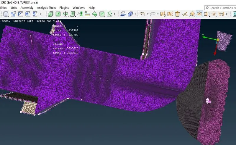
After each volume is re-meshed, the volume mesh can be viewed for each component.
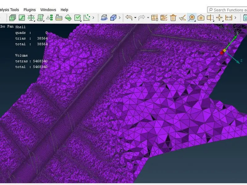
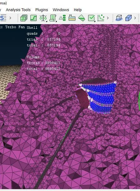
Cross-sectional view of volumetric mesh
Results:
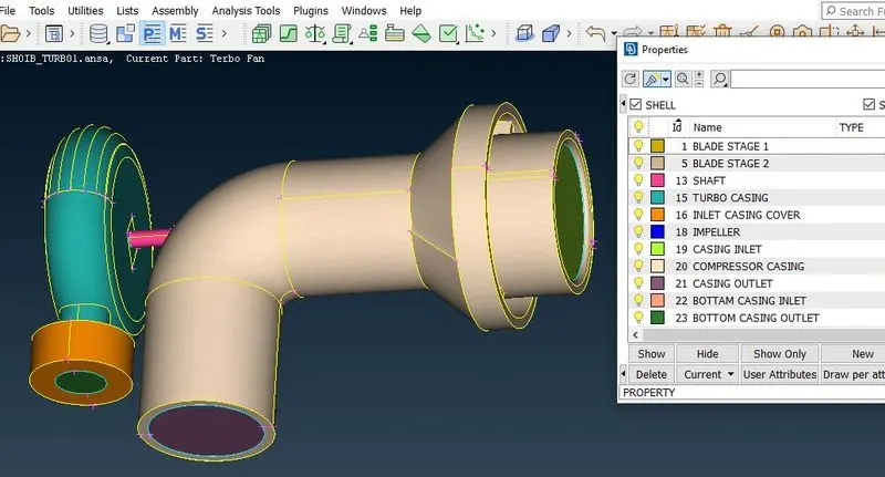
Completed geometry clean-up with all the inlets and outlets closed to create a closed volume:
Surface Meshing is achieved with different mesh lengths as per the question:
Volume mesh created for the fluid volume region along with cut sections to view the 3D mesh:
Learning outcome:
- Checking for geometry errors and correcting the geometry using different geometry editing tools.
- Deleting overlapping regions to improve mesh quality and avoid errors while volume meshing.
- Correcting the triple cons and single cons accordingly as per the geometry requirement.
- Using fine under auxiliaries helps in giving a finer surface finish at the connecting region.
- Creating surface mesh individually and also maintaining mesh length range at the contact region between 2 different mesh lengths.
- Identifying and creating volume mesh only for the fluid region part.
- Tools to create volume mesh.
Conclusions:
- Achieved volumetric mesh of the turbocharger model.
- Different mesh length sizes tend to give errors at the contact regions of 2 different mesh length regions, therefore mesh ranges can be given to avoid erasing of mesh.
- Volumetric mesh can be achieved only after creating surface mesh successfully, or else the geometry can give fatal errors while volume meshing.
- The overlapped surface can be deleted using the universal delete option.
- Unnecessary single and triple cons can be removed and edited using different tools such as cons project, topo, release, and fine tools while geometry clean up.
- Successful volumetric mesh can be achieved only after correct geometric clean-up and surface mesh.
The link to the file is:-
https://drive.google.com/file/d/1l_hLZ1uxFlknp0Eo6fCYDcA9eveOz4O0/view?usp=sharing