Week 3 Challenge : CFD meshing on Turbocharger
AIM:
For the given model, to check for the geometrical errors to make appropriate volumes, create and assign PIDs. To perform surface mesh with the given target lengths as per PIDs.
- Blade stage-1 = 1 mm
- Blade stage-2 = 1 mm
- Impeller = 2 mm
- Shaft rotor = 1 mm
- Turbo casing = 5 mm
- Compressor casing = 5 mm
- Inlet casing cover = 5 mm
Then to perform Volumetric mesh for the required volumes.
DESCRIPTION:
GEOMETRY/TOPO CLEAN UP:
Loading the geometry model in ANSA
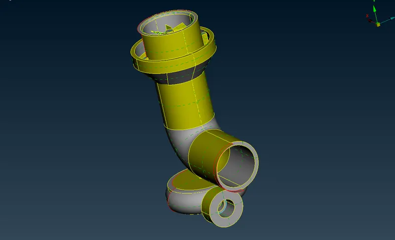
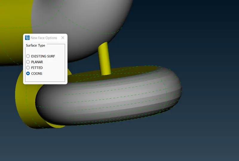
Here we see a single con, so need to fill it
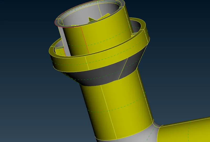
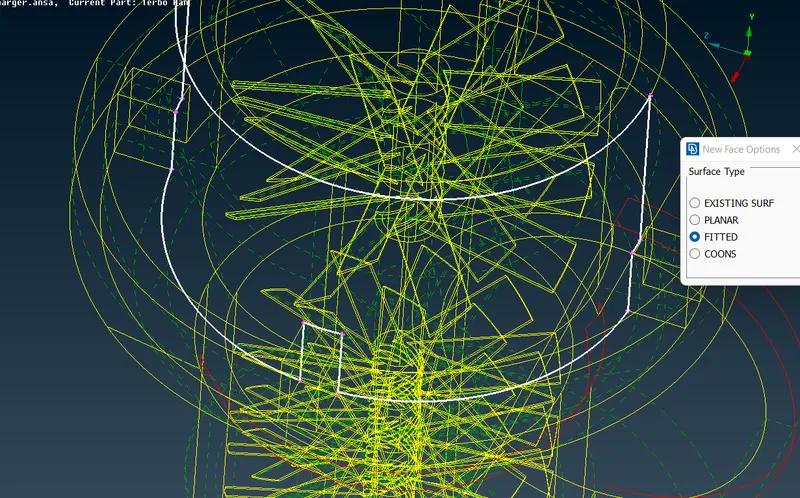
A proper surface is not getting created
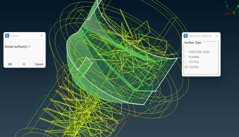
So we need to create small different surfaces by using hot points.
For this we need to project the hotpoints on the other face of this surface
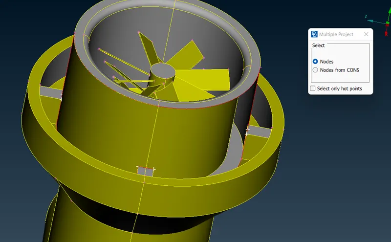
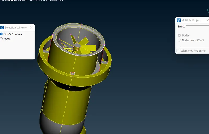
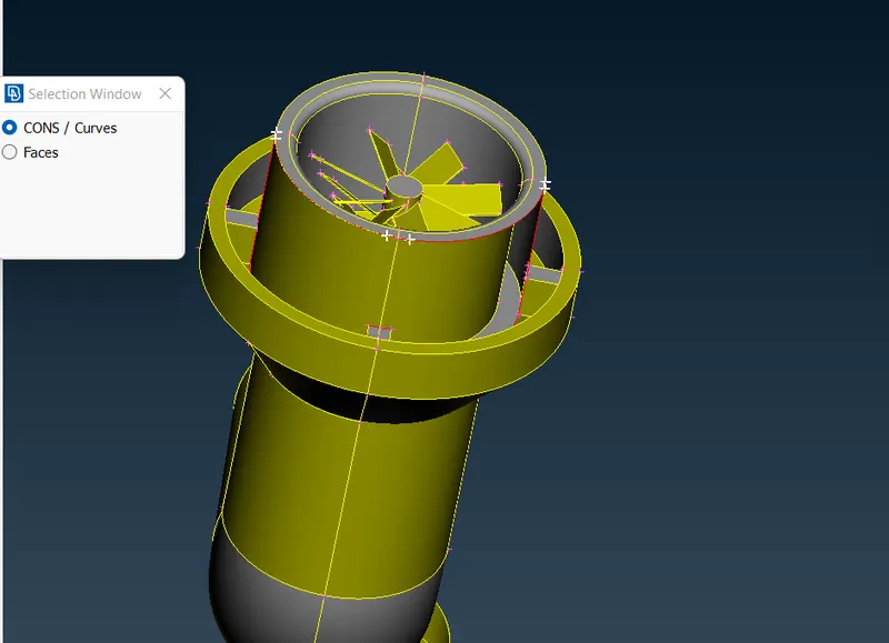
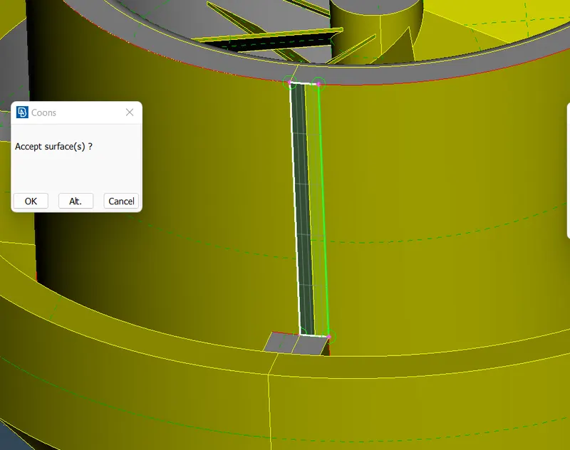
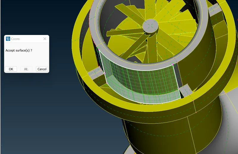
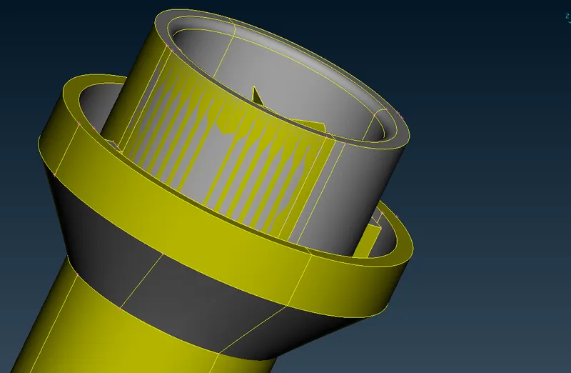
So we have fixed ultimaterly this part but still we see glitchings on the surface. We need to fix this glitchings.
Using 'TOPO tool' to check are there any triple cons
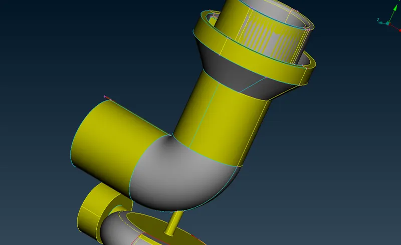
By using the delete too with PID region we see that we are able to delete the glitchings
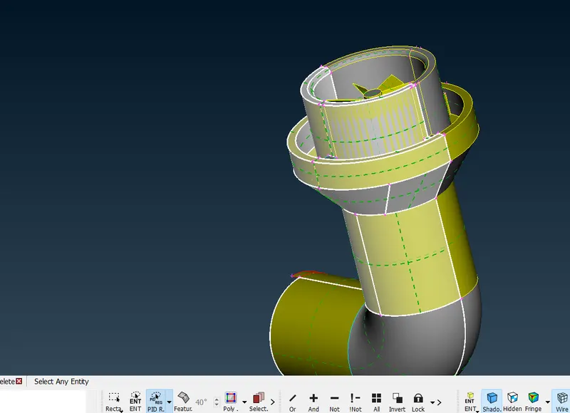
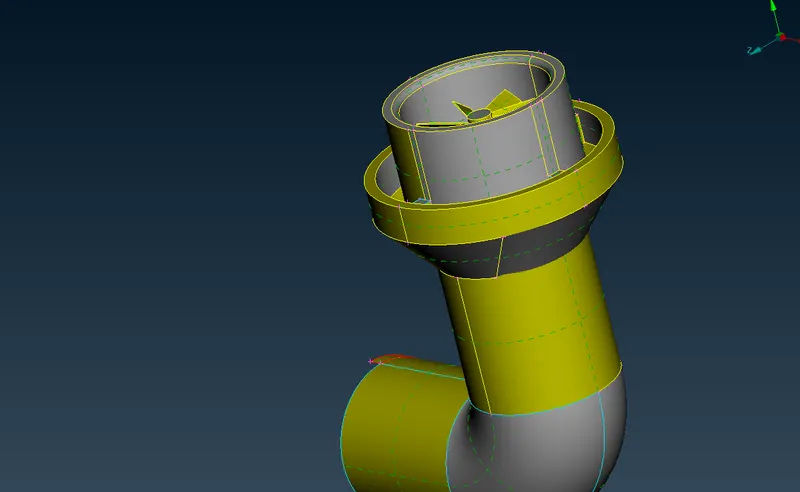
For the other surface

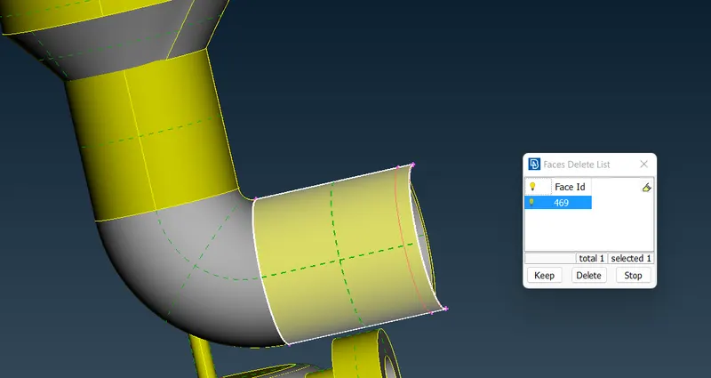
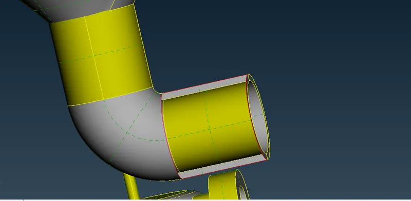
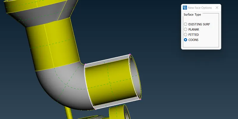
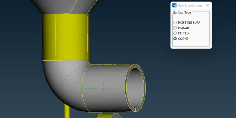
Creating surface cleanup for another part
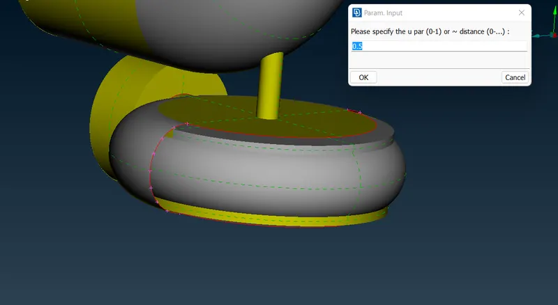
so creating hot points using parameters
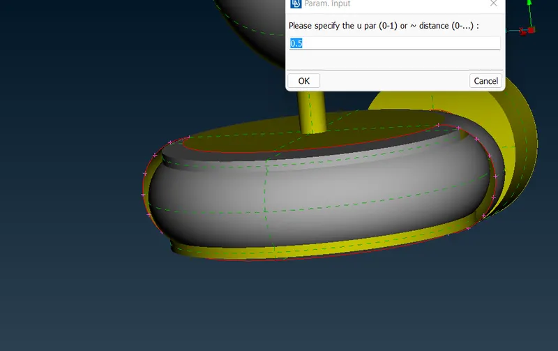
On the other side creating hotpoints using parameter
Now creating one by one alternate surfaces as follows
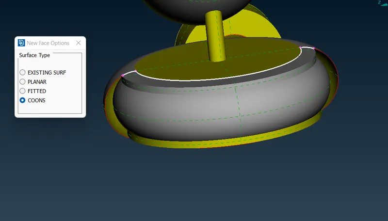
Ultimaterly whole surface is created as follows
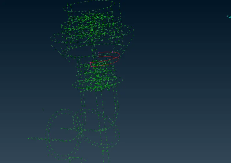
In the wireframe mode we see still a single con
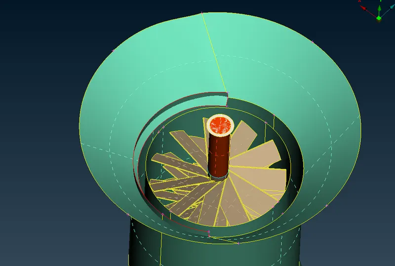
Seecting first group
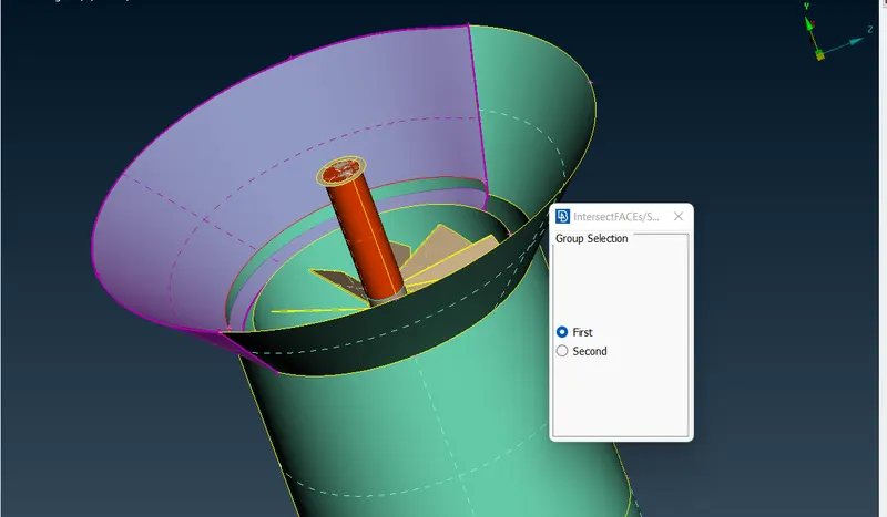
Then second group
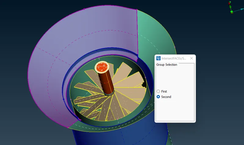
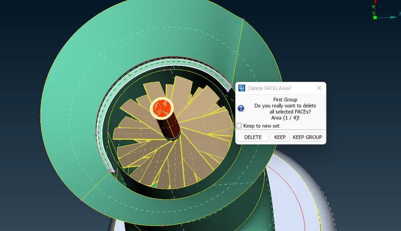
Now we got the triple con so deleting the single cons
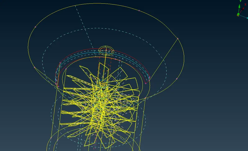
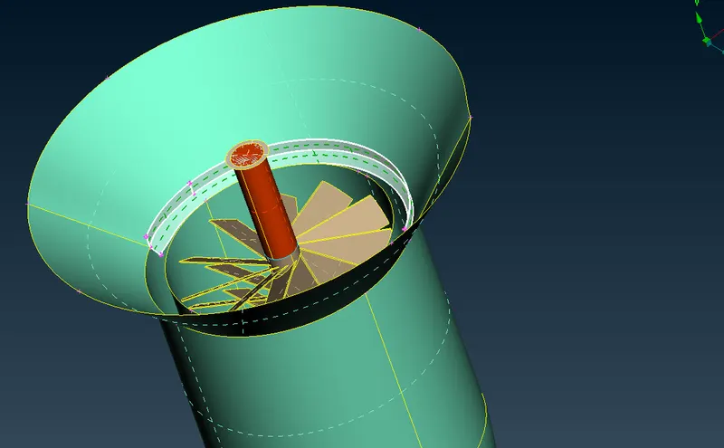
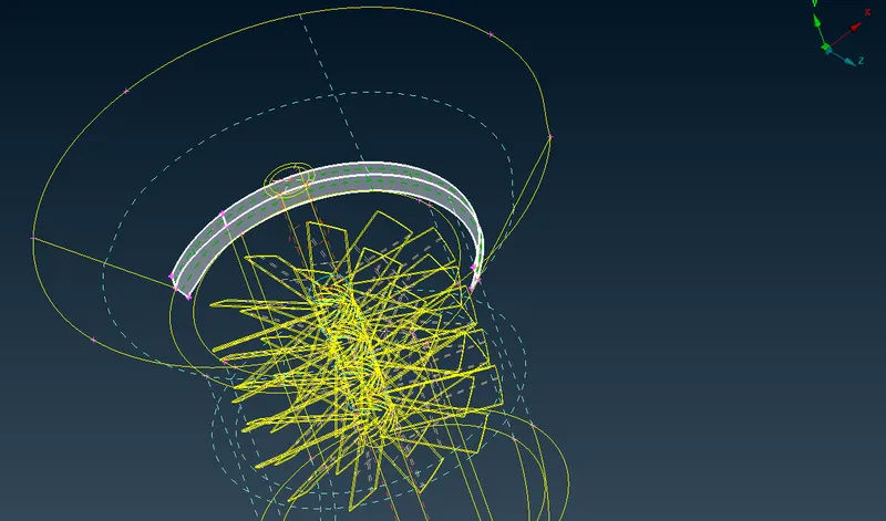
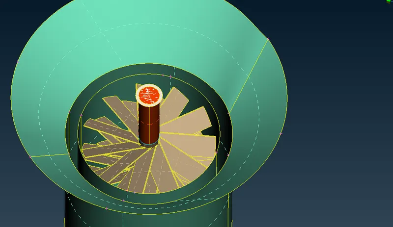
Leaving triple cons we see all the geometry checks are accepted
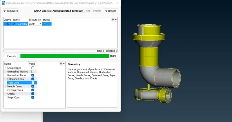
Now we need to fix the triple cons for all the surfaces
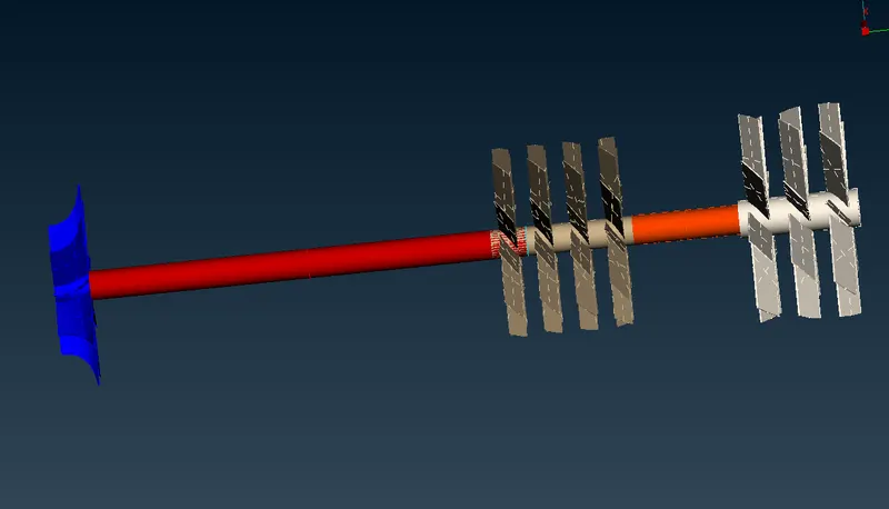
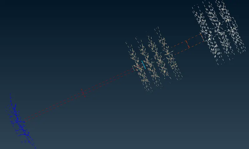
Using the CON project tool, we select the double CON then left click on the required surface to cut the CON and the use fine tool to fine the surface and then delete it. Now its fixed
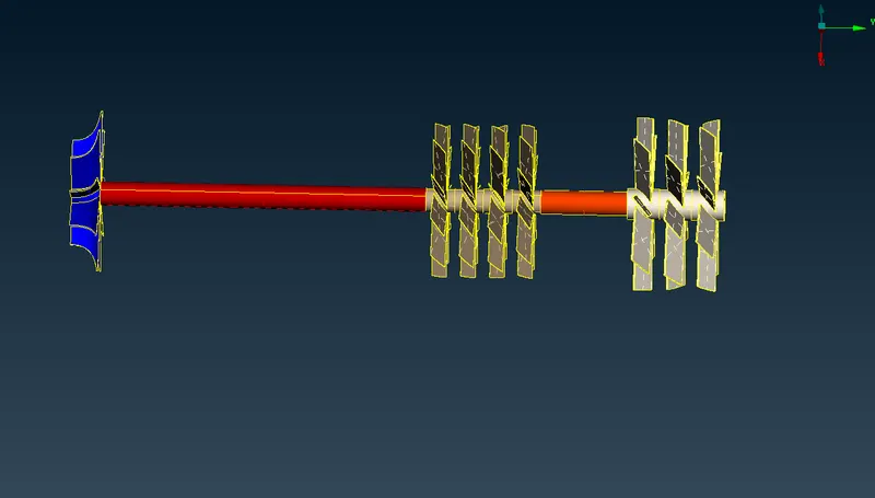
Executing Geometry check for the above model we see no triple, single cons
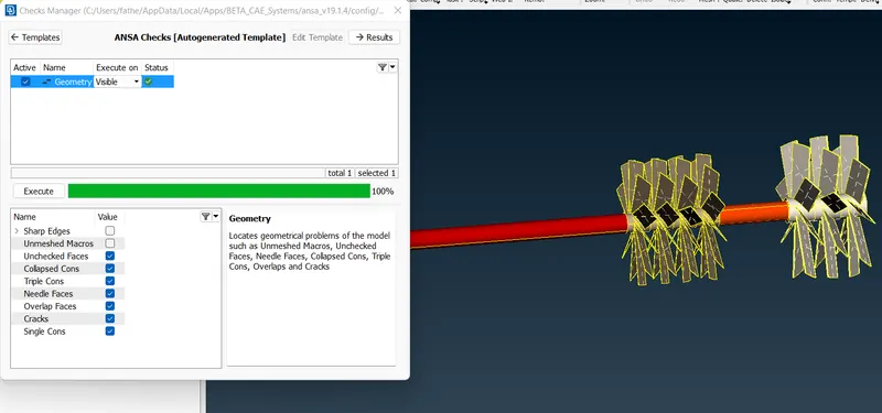
Now performing Geometry checkup for the entire model
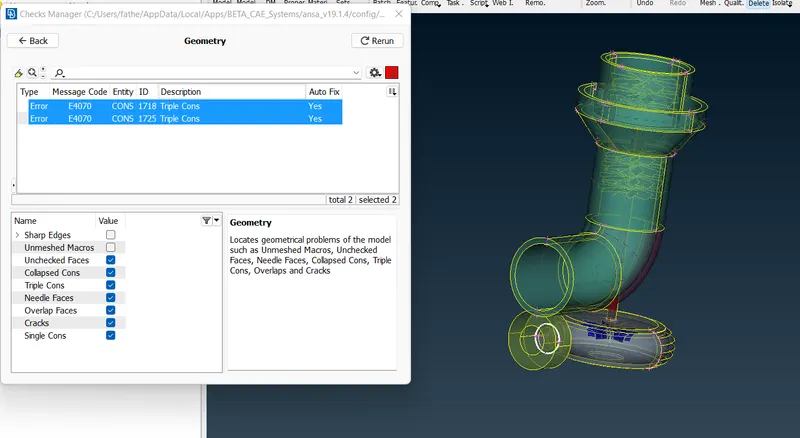
We find that only 1 triple con is present now which is required and its not and error as if we are trying to delete, it is deleting the surfaces connected to it.
Now checking if there are any openings in the geometry if not when moved for executing the volumetric mesh it gives error. So we don't find any openings.
Now assigning the names to PID manager.
Checking and examining for the below component so that it doesn't have any other component with it and naming it OUTER CASING
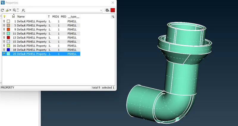
Examining the below part for PID we find the surface is open at bottom and we need to close it
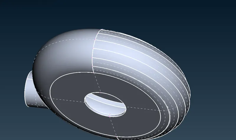
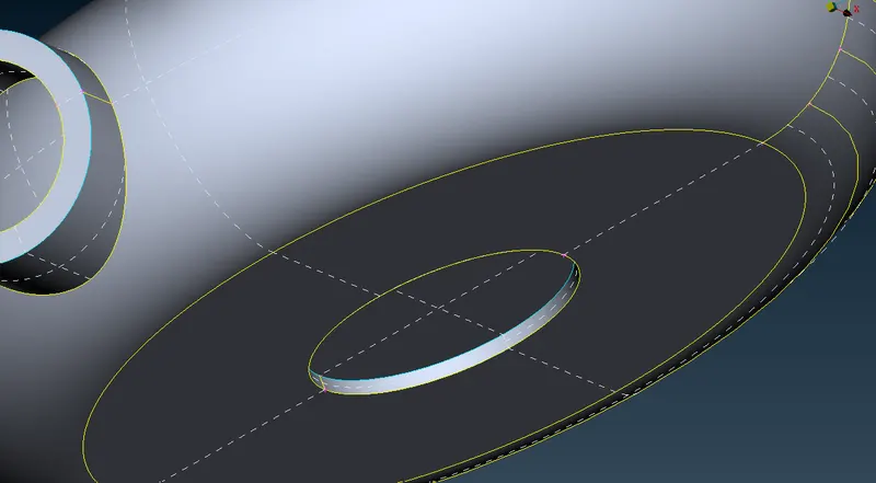
And now even closing the inlet and outlet as follows
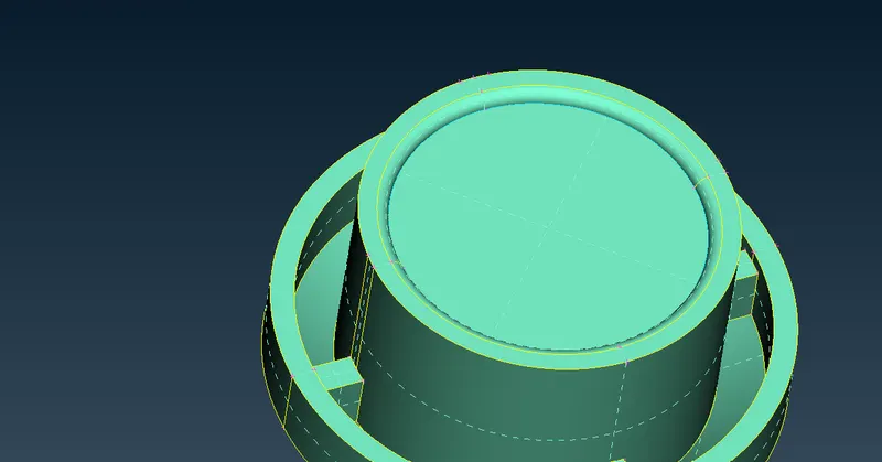
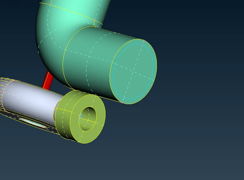
As we are able to see the interior components from top view we need to even close the below chamber
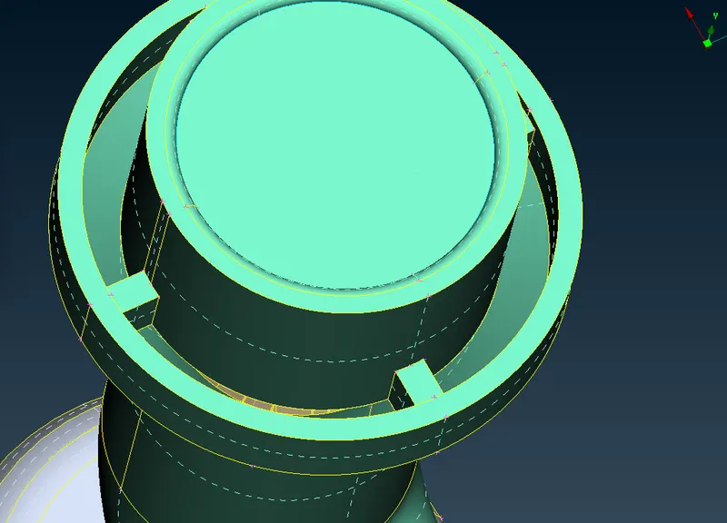
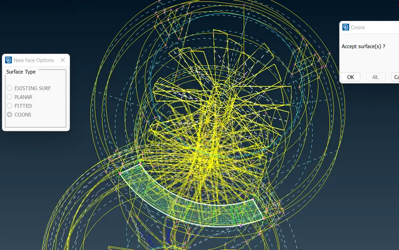
Not this part is fixed
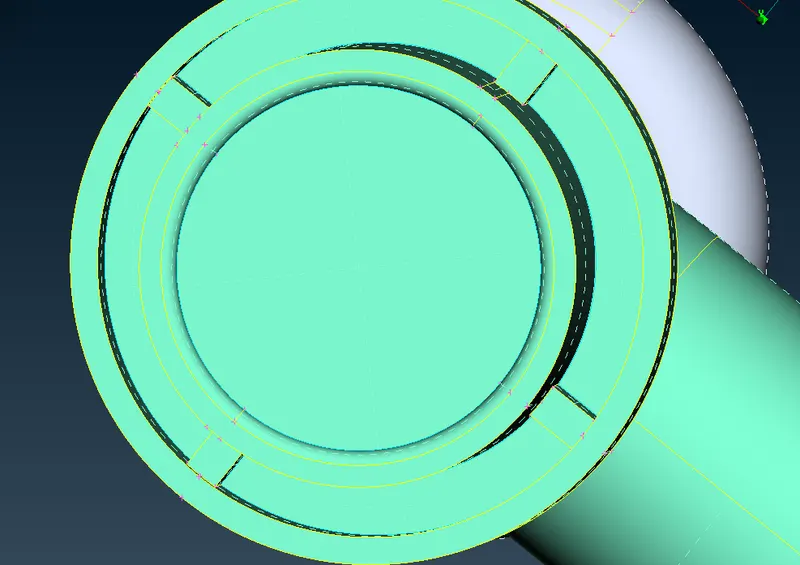
Now closing the below part
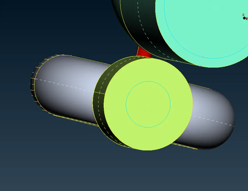
Applying now the PIDs
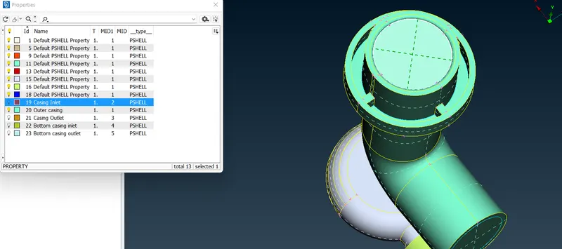
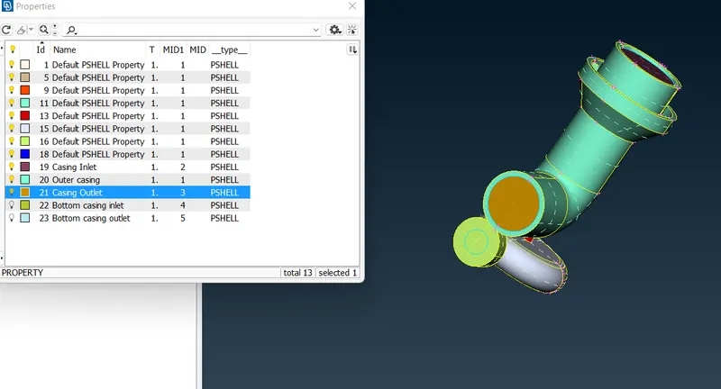
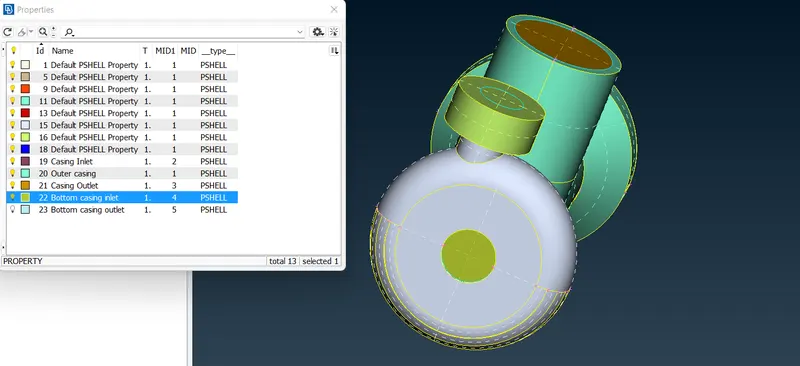
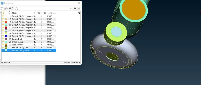
Renaming them
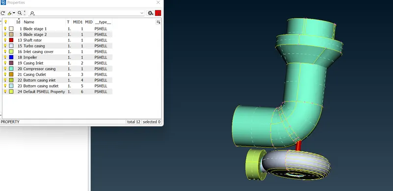
Checking for single cons, we don't see any
Checking triple con
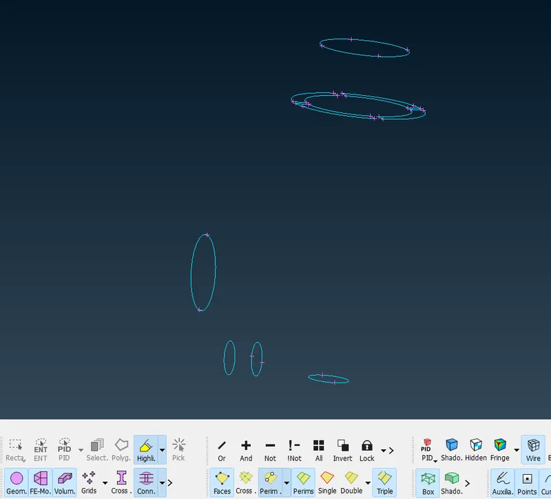
These triple cons are acceptable.
MESHING:
Before moving to Volumetric mesh we first do the meshing.
So before meshing we check for geometry and we see only the triple cons.
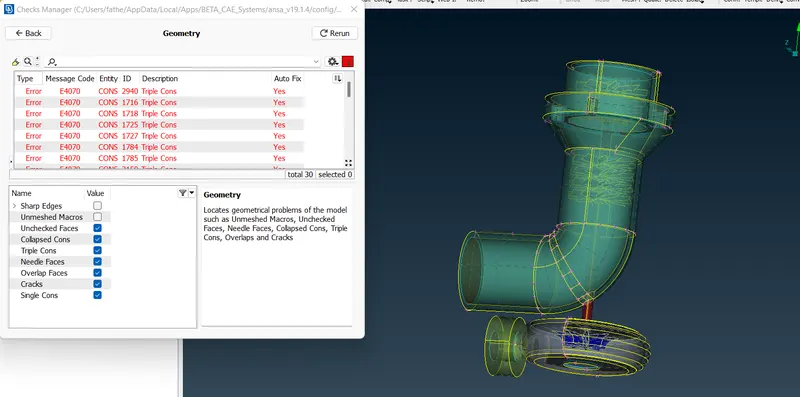
Now giving the quality for the meshing target length by selecting the PIDs according to the given target lengths
- Blade stage-1 = 1 mm
- Blade stage-2 = 1 mm
- Impeller = 2 mm
- Shaft rotor = 1 mm
- Turbo casing = 5 mm
- Compressor casing = 5 mm
- Inlet casing cover = 5 mm
For compressor casing with 5mm target length
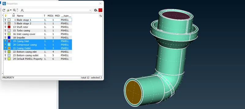
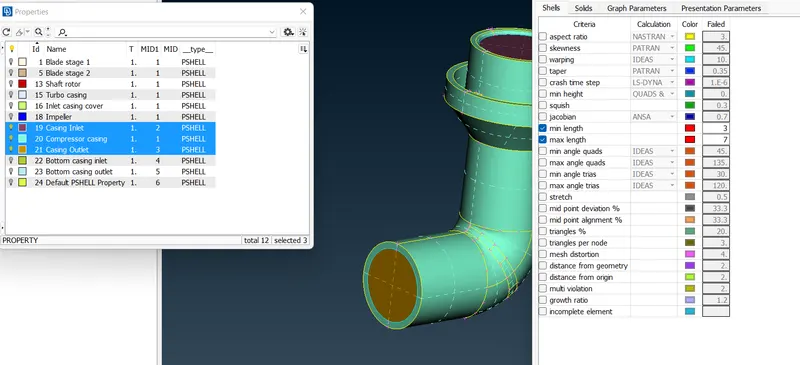
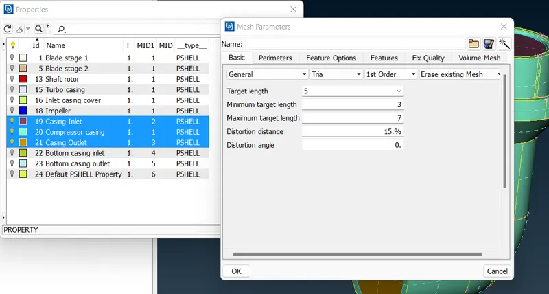
So, meshing for the compressor is done
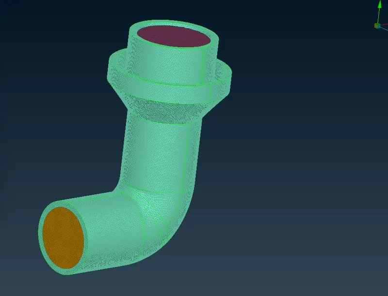
Now, for turbo casing and inlet casing cover with 5mm target length
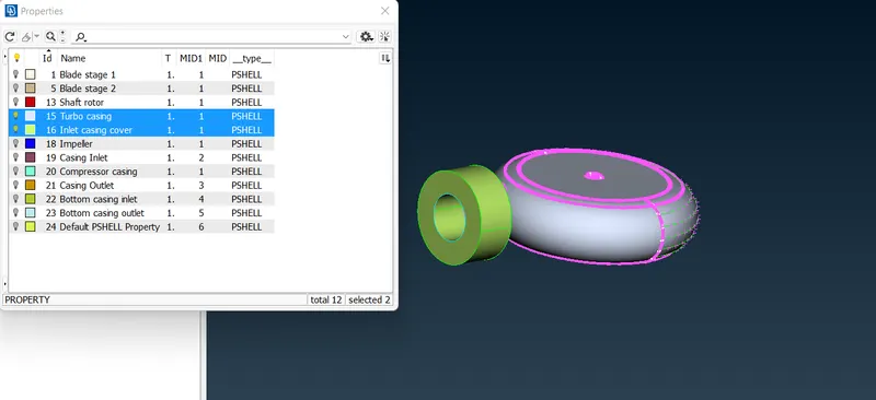
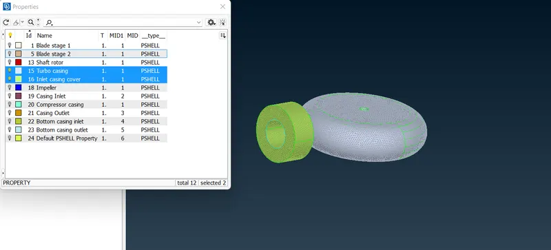
Mesh is completed as follows
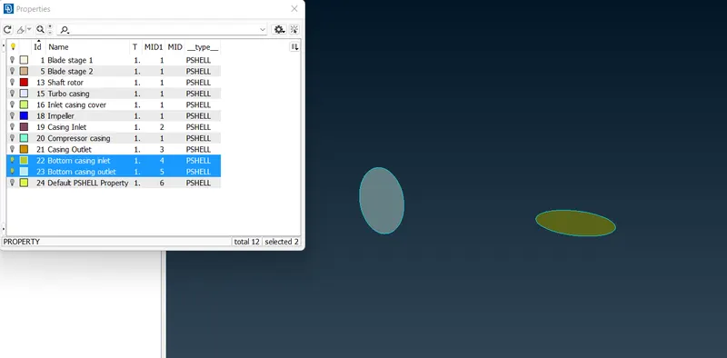
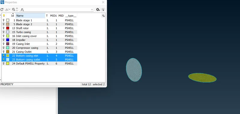
Now meshing for Bottom case inlet and outlet with target length 5mm
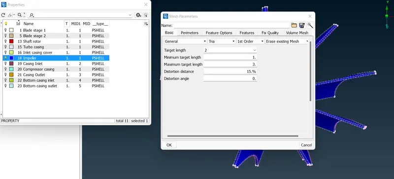
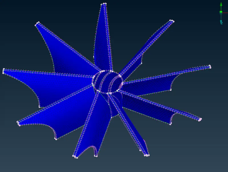
For impeller with target length of 2mm
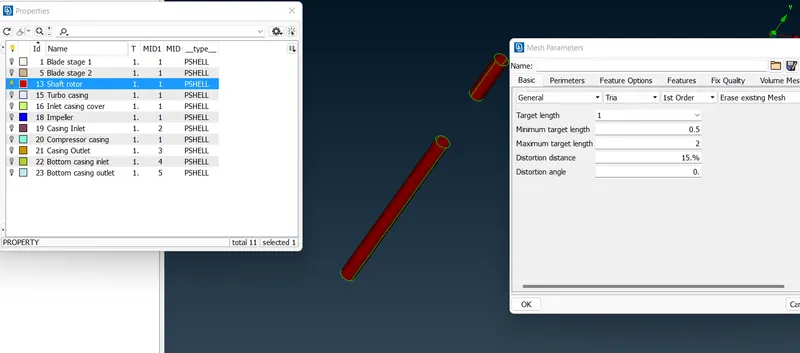
For shaft rotor with target length 1mm
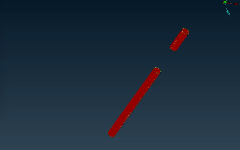
For stage 1 and stage 2 blades with target length of 1mm
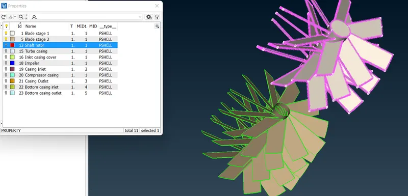
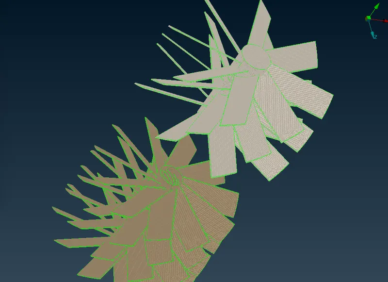
The complete geometry has been meshed successfully now
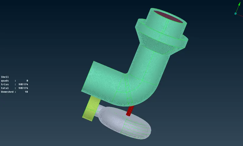
But here we see unmeshed are 18 surfaces so need to mesh them
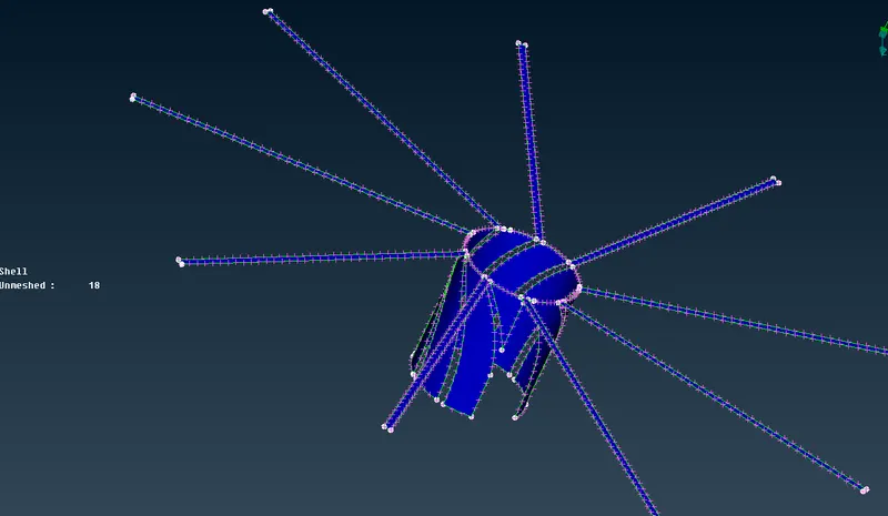
As these are parts of impeller we use 2mm to mesh
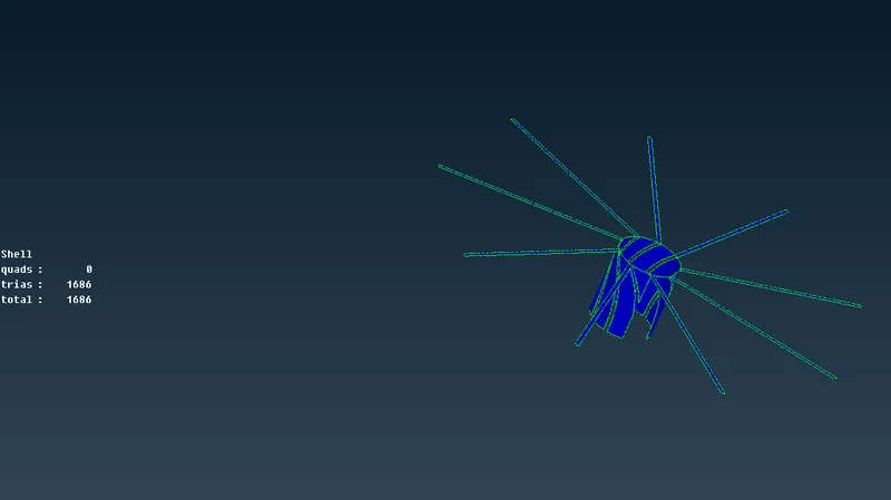
Even after fixing still we see 2 unmeshed surfaces
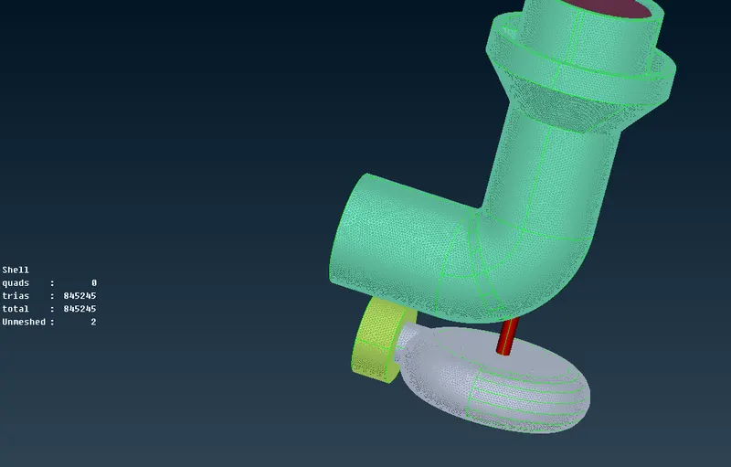
fixing them with 1mm target length for shaft rotor
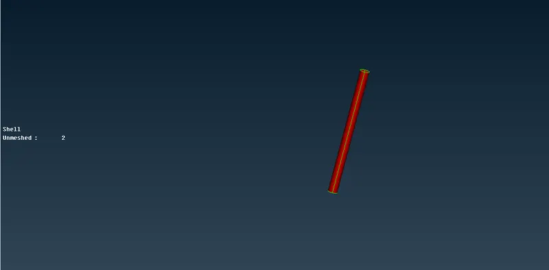
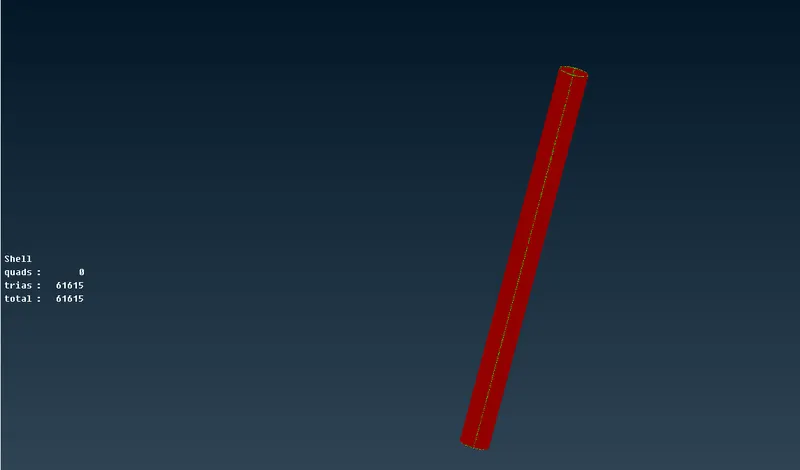
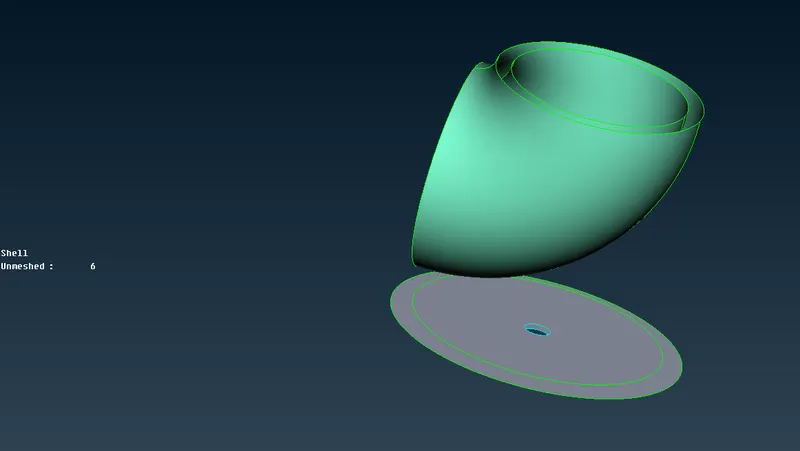
Meshing inside parts
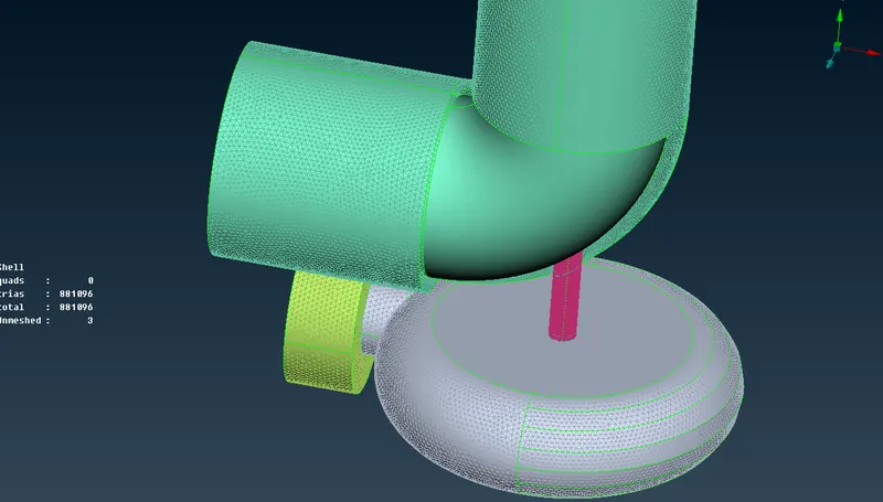
Using Cut>reconstruct
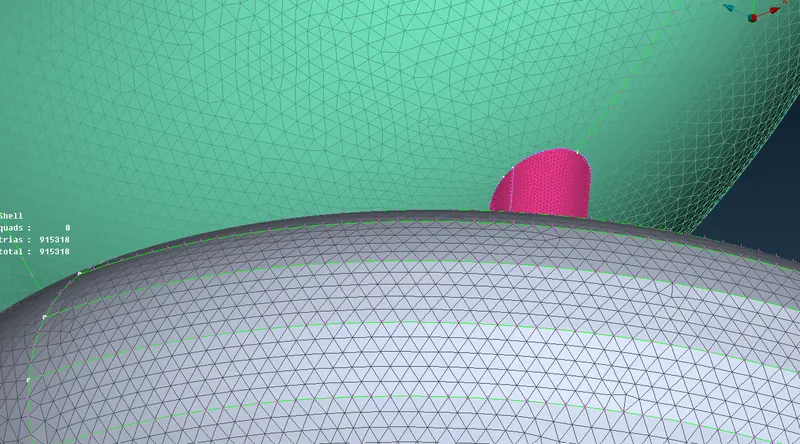
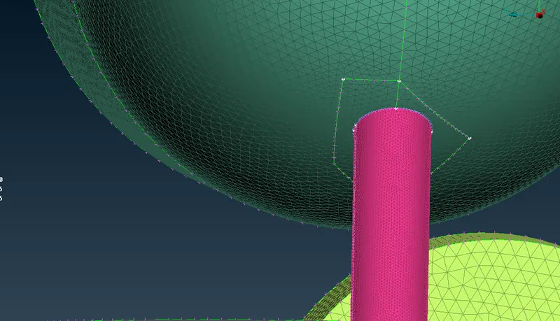
Now its fixed
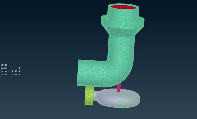
VOLUMETRIC MESHING:
As there are no unmeshed surfaces now we move to volumetric mesh
We go to define and select the whole data base
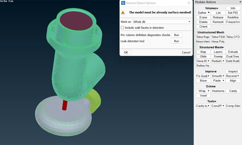
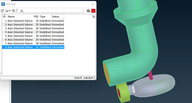
These are the volumes detected automatically be ANSA
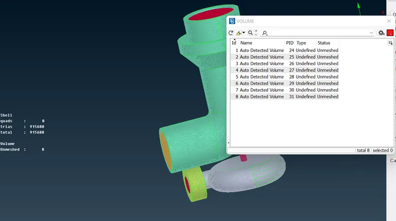
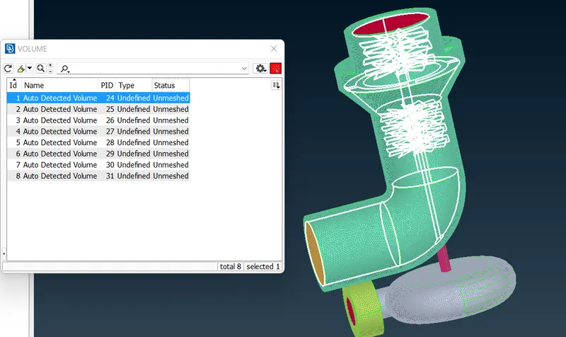
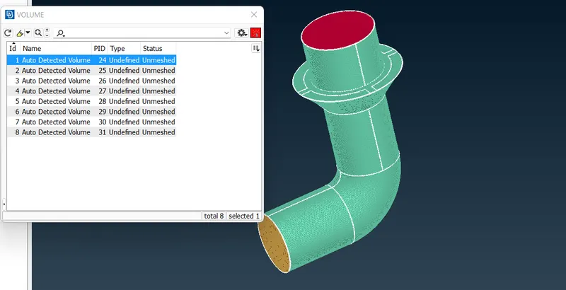
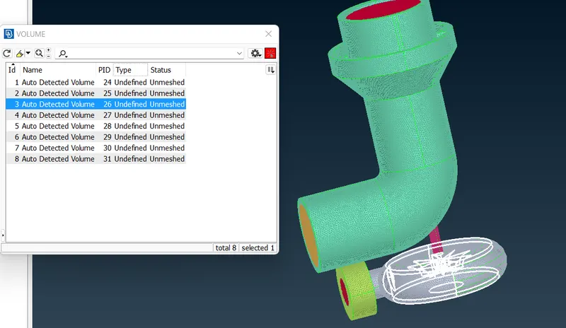
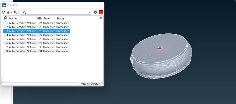
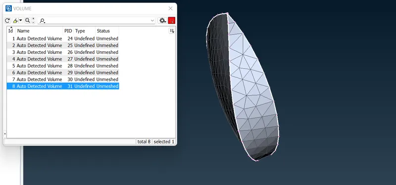
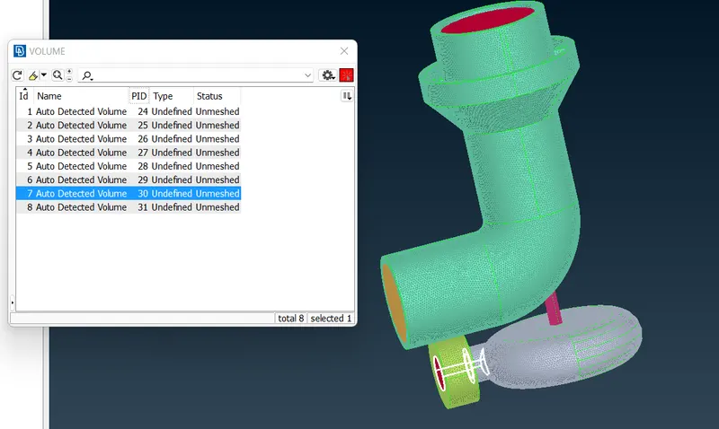
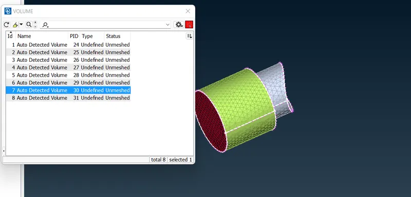
From the above volumes defined we require only the volume of components where the fluid flows. Below are the components we require (24,26,30,31 PIDs) and all other to be deleted as not required
PID 24
PID 26
PID 31
PID 30
We are left with the following
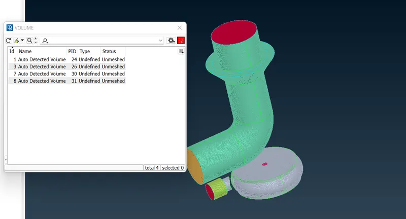
Remeshing for the PID 31
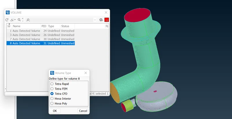
All the required volumes are meshed using Tetra CFD
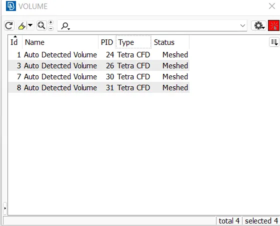
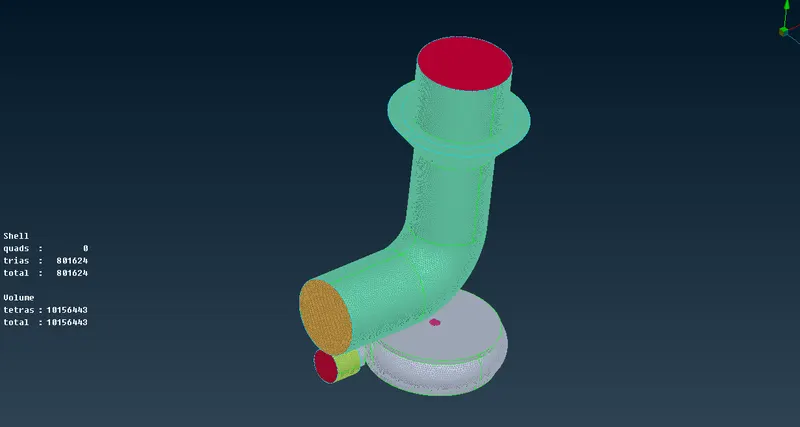
Now if we change to Topo mode we see glitchings as volumetric mesh is generated
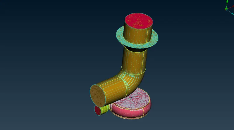
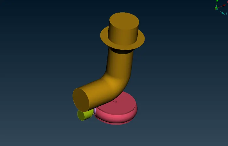
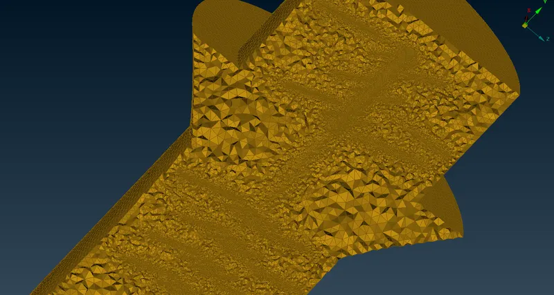
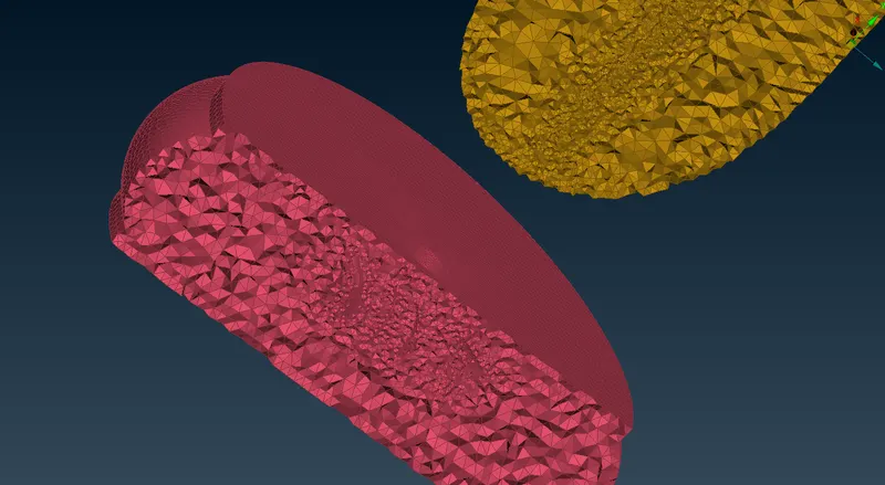
Turning off the geometry we see the volume created using meshing as follows
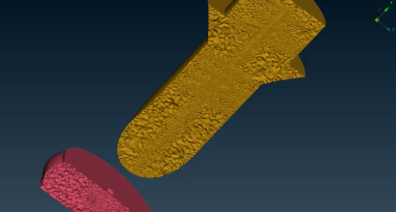
If we cut into half we see the volumes created
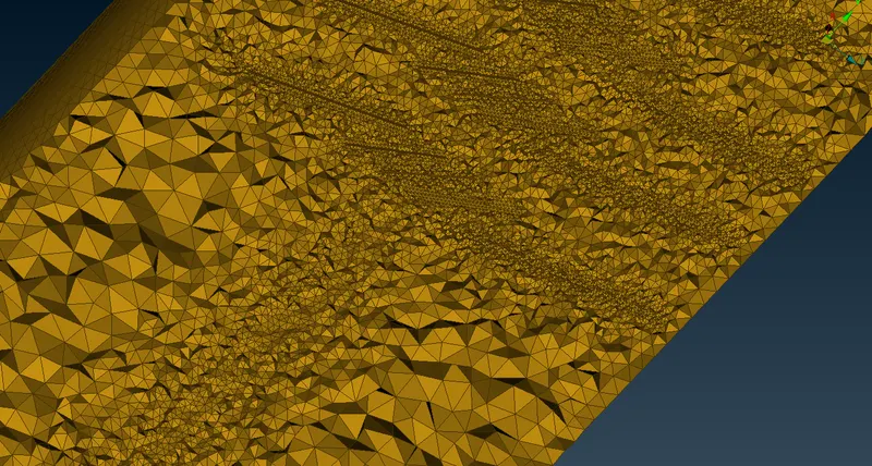
Also we see where there was blades and shaft the volume is varying 1mm to 5mm thereafter
CONCLUSION:
Thus, the geometrical errors like single, double and triple con are checked and PIDs are assigned accordingly to the requirement and the surface is generated for with the given target lengths. Then volumetric meshing is performed for the volumed required successfully.