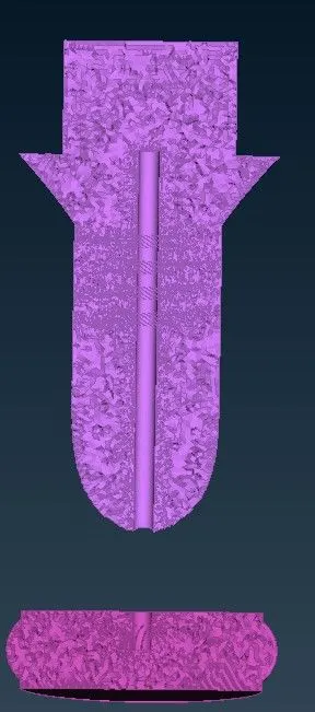
Week 3 Challenge : CFD meshing on Turbocharger
SURFACE AND VOLUMETRIC MESHING ON A TURBOCHARGER
OBJECTIVES
PART-1
- First we check for the geometrical errors to make appropriate volumes.
- Assign the PIDs that are given.
PART-2
- Generate surface mesh by assigning the appropriate size.
- Generate a volumetric mesh by creating an appropriate control volume.
- The meshing model size of each PID is as follows,
- Blade stage-1 = 1 mm
- Blade stage-2 = 1 mm
- Impeller = 2 mm
- Shaft rotor = 1 mm
- Turbo casing = 5 mm
- Compressor casing = 5 mm
- Inlet casing cover = 5 mm
PROCEDURE
PART-1(check for the geometrical errors to make appropriate volumes)
I-First we upload the Turbocharger model, Switch on the shadow mode to display the whole model. Change the draw mode from ENT to PID.
II-Switch on the cons visibility modes through the presentation parameter in quality criteria.
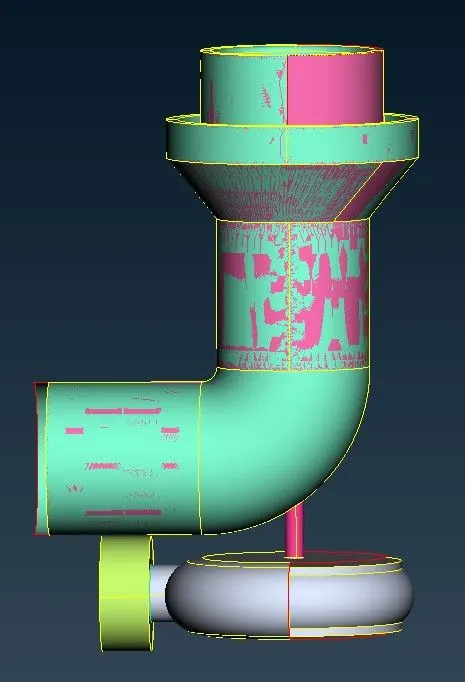
III- As we saw in this model, there are some errors like overlapped surfaces, missing faces, and some surfaces crossing each other but are not intersecting. To fix that we use intersect tool and then delete the unwanted extruding surfaces.
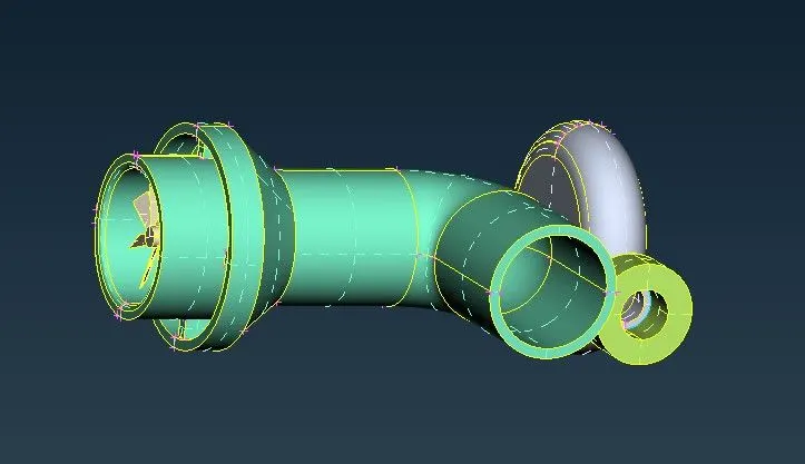
IV- Assigning the PIDs that are given.
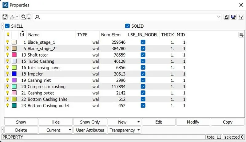
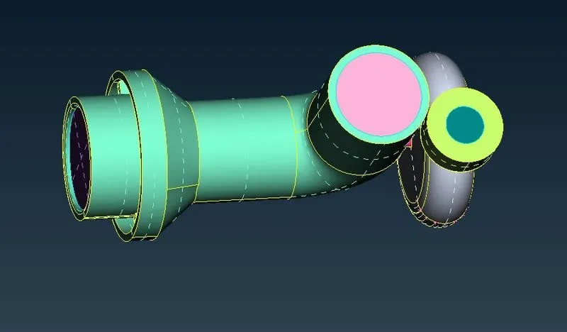
V- After assigning all the PIDs to the model, then we have to connect all three blade_s1,blade_s2, impeller, and shaft rotor and we have to remove the extra surface in between them we got some single edges, To fix that we need to join the edges by using release and toop tool.
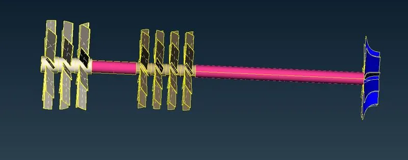
VI-In order to get a perfect geometry, We have to do a geometry check and then extract the single cons and the unwanted triple cons also.
PART-2(I-Generate surface mesh by assigning the appropriate size
-To get our desired mesh, We need a clean geometry as we have done above.
-In Mesh First, we gave all the different sizing of PID in mesh parameter, Quality criteria and assigned the mesh size using the "length tool"
-In the mesh parameter we set the element type as 'Tria'.
-The sizing of all PIDs is given Below,
- Blade stage-1 = 1 mm
- Blade stage-2 = 1 mm
- Impeller = 2 mm
- Shaft rotor = 1 mm
- Turbo casing = 5 mm
- Compressor casing = 5 mm
- Inlet casing cover = 5 mm
The Mesh
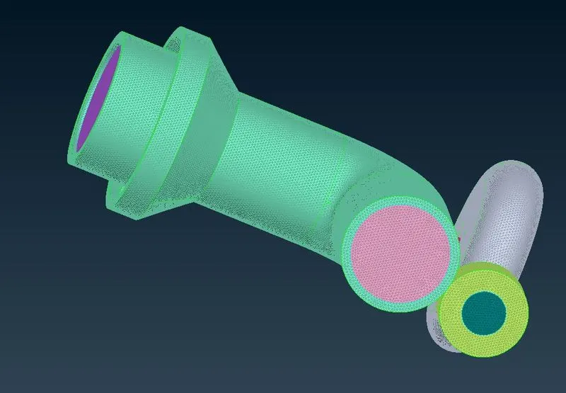
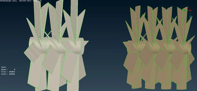
-The increase in the size of the mesh from one PID to the next attached PID can result in some parts that should have a small mesh size having a larger mesh size.
-It is preferred the part having a larger mesh size can have a size reduction, but a part having a smaller mesh size should not go beyond the specified limit.
-To fix this we need to reassign the length of the PIDs having the inconsistency by using the "Length" tool and also enabling the "Remesh macros" option. Then we can simply re-mesh the parts to get an appropriate mesh.
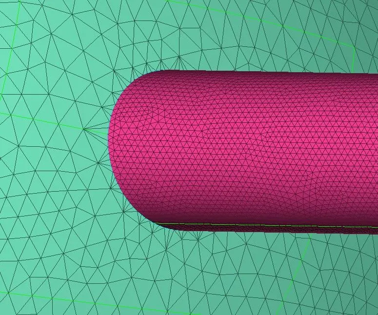
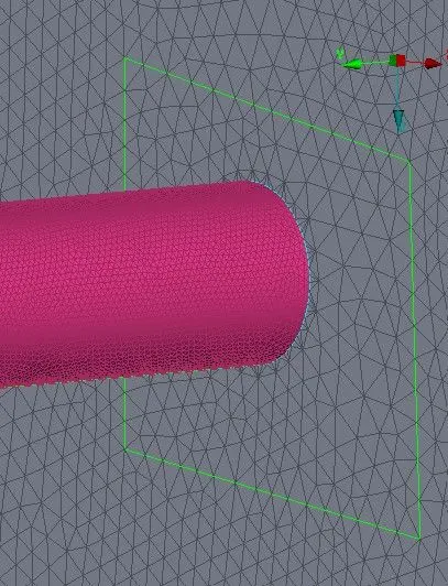
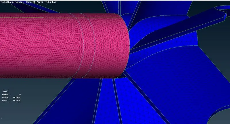
-We can see that some regions are non-uniformly distributed mesh size on the compressor that tends to change the mesh size abnormally.
.
PART-2(Generate a volumetric mesh by creating an appropriate control volume)
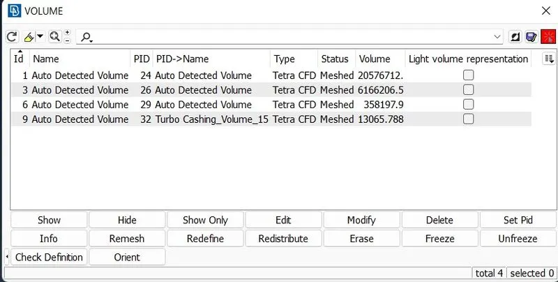
To create a volumetric mesh, we have to first create a volume element. For that, we have to use the Define tool in the volumetric module. This cause ANSA to automatically detect all the volumes that are present in the geometry.
We need to delete all other Mesh except than volumetric part as it is not required. Also as there is no flow inside the shaft rotor, blade_sage1,satge_2, and impeller, hence we can delete these volumes.
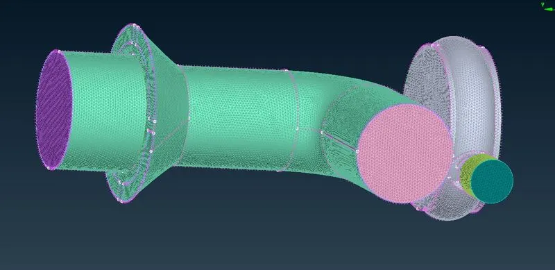
-We used the tetra CFD tool that could define the undefined mesh.
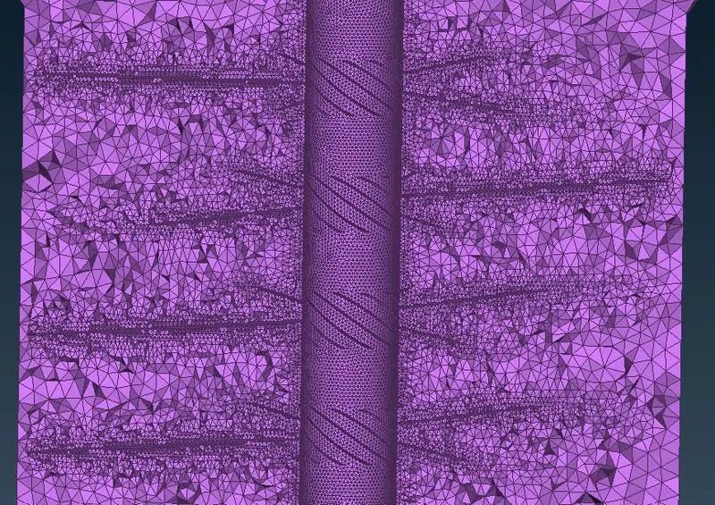
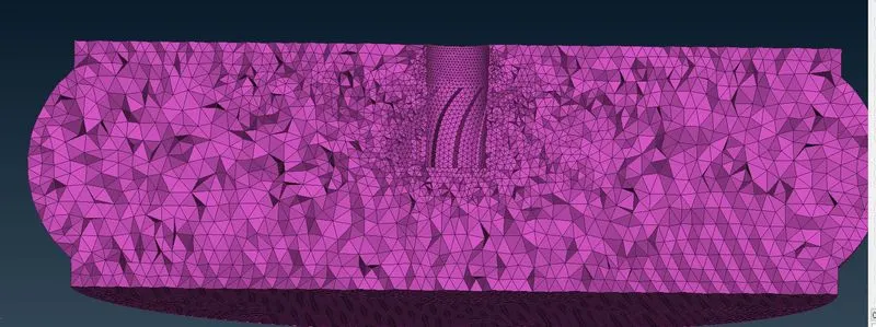
-To see the volume inside, we can use the Not tool and intersect the volume from the middle.Some intersect parts are given below,