Week 3 Challenge : CFD meshing on Turbocharger
Week 3 - CFD Meshing of a Turbocharger
Topology cleanup:
The model when loaded into answer contains a lot of geometric errors hence the topology cleanup was performed first. Here as seen in the pictures the single cons are fixed by creating new surfaces as per fitted surfaces and coons.

At the locations where the entire surface creation was not possible, smaller surfaces were created and then they were integrated into a complete surface.
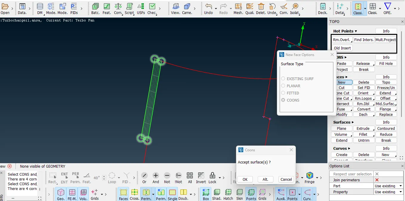
As seen below in this part of the geometry was intersecting with the other surfaces hence it was trimmed down and then old obsolete surfaces were deleted to create a non-intersecting surface.
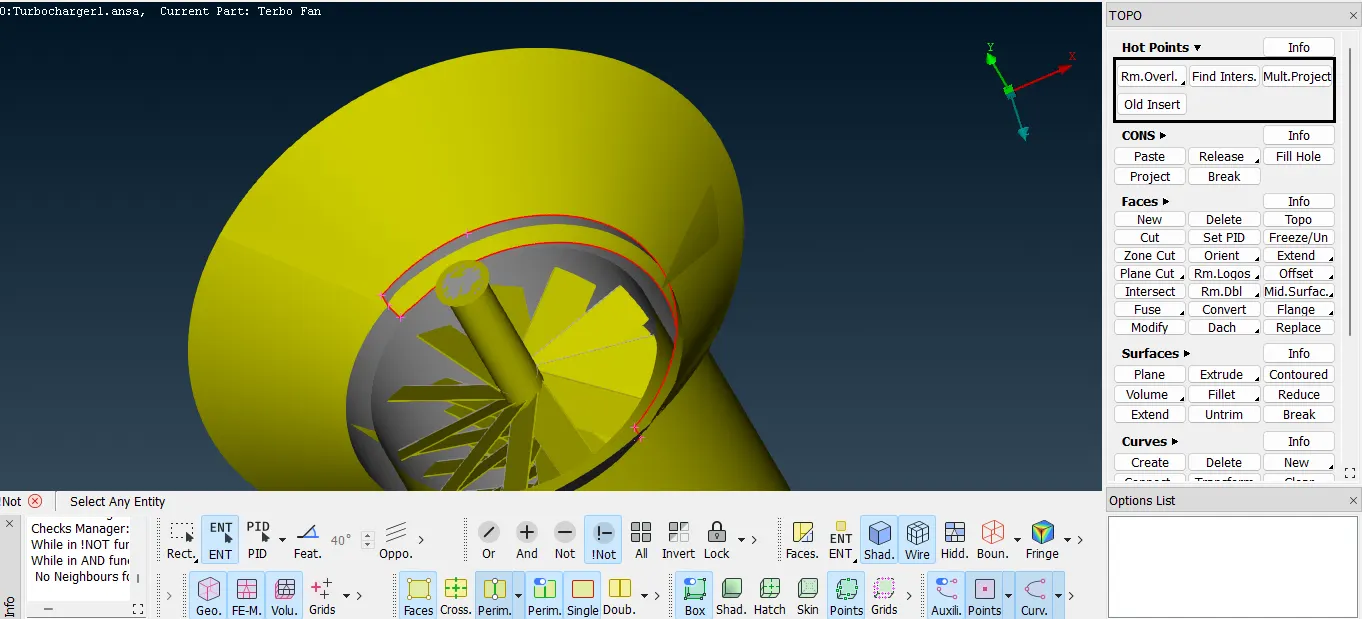
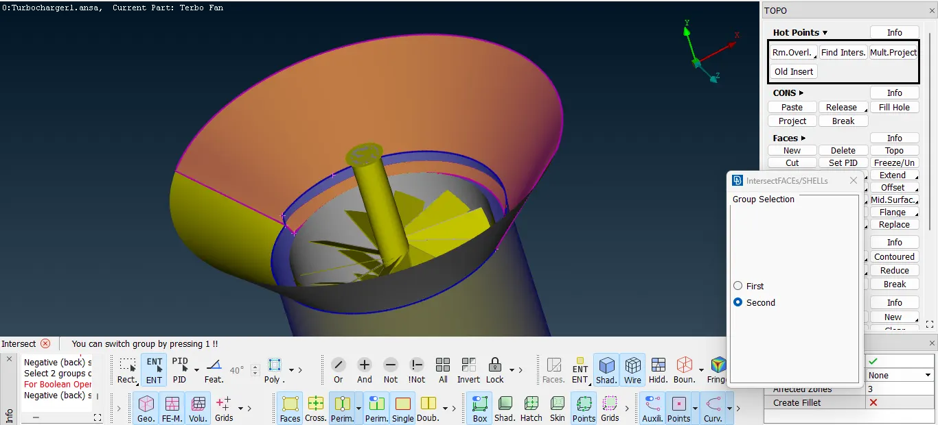
For this following curved surface the surface creation in one attempt was not possible so for that additional hotpoints were created on the curved edge, and layer by layer surface strips were formed eventually creating the entire curved surface.
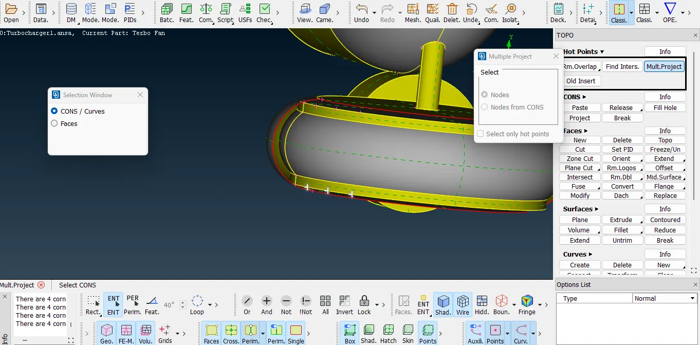
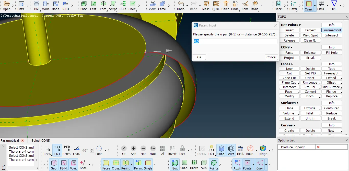
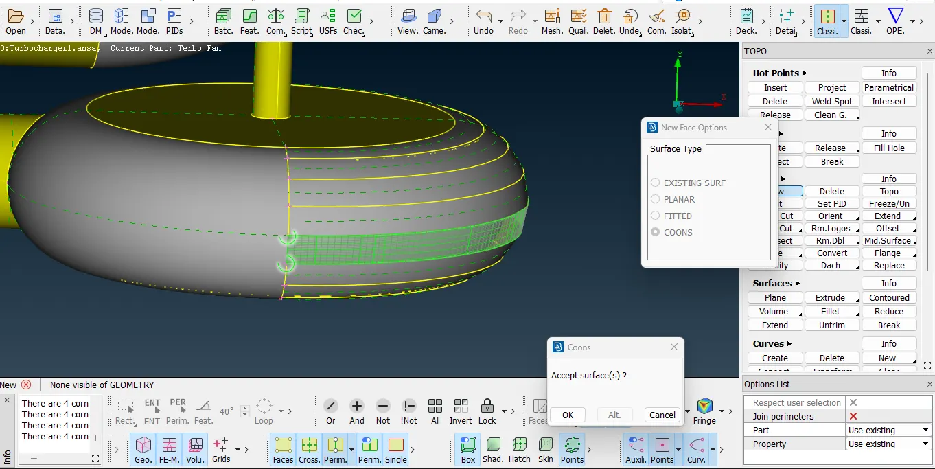
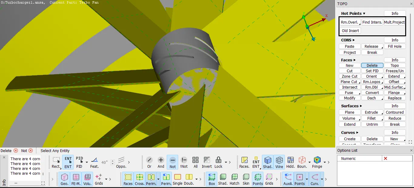
After this the shaft was made into an entire single component by deleting the circular faces present in between the cylindrical shaft. Here the overlapping faces were deleted by releasing the interconnected surfaces and creating new topology over there so it created a double connected surface. Likewise the whole shaft geometry excluding the blades was formed into a single component.
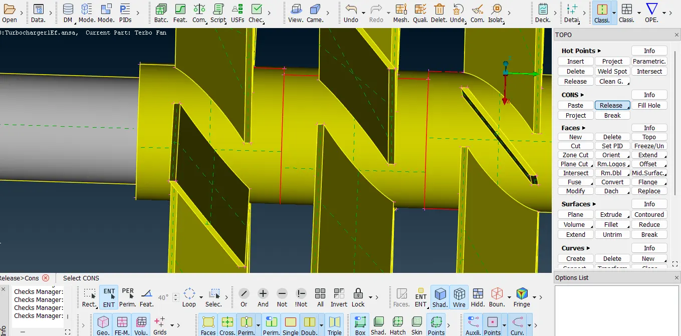
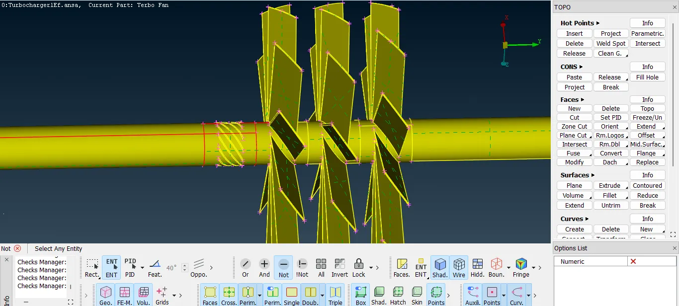
At some locations where the surface was overlapping, the intersecting surface was deleted and a single con was formed, hence this was again projected on the same component, on the same face creating an abrupt shape of curvature. This was refined afterwards to make the proper circular edge.
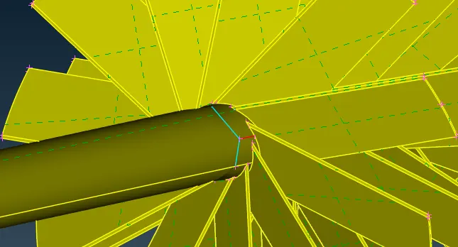
In addition to that as the shaft is different diameters along the length while deleting the surface is new single surface was created to join the shaft as a whole.
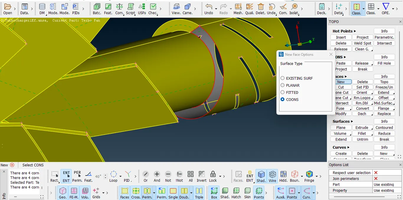
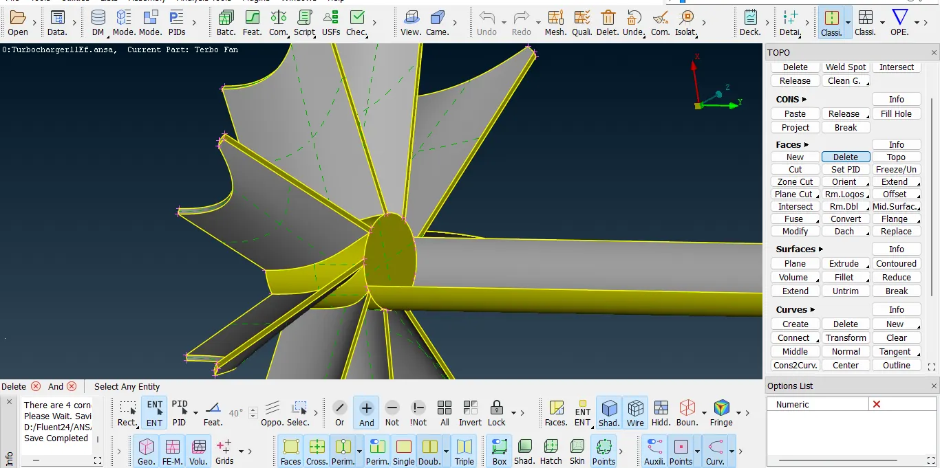
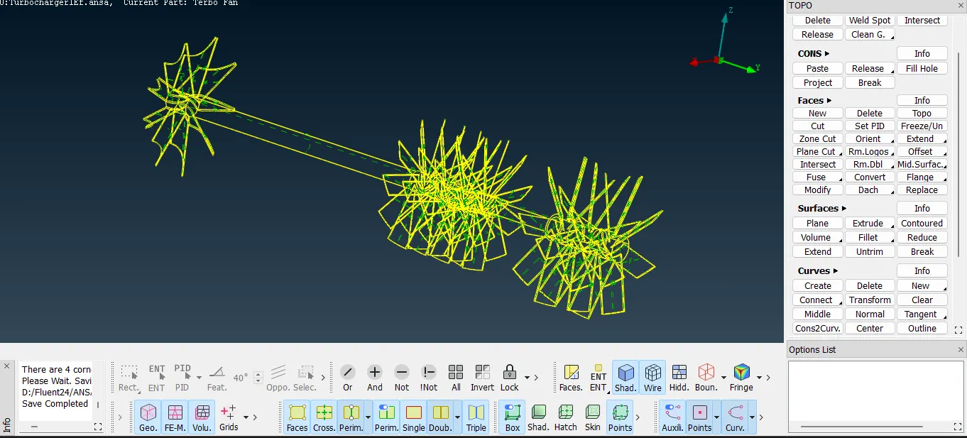
Secondly as the new surfaces were created, there were some intersection errors and were fixed by deleting the additional surfaces which were overlapping, and it was done by projecting the single cons on the component faces.
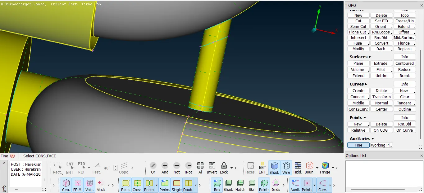
Furthermore since the fluid analysis has to be performed inside the geometry the component geometry needs to be closed so for that the open holes were sealed by creating new surfaces. This was done for the outer compressor casing as well as the below attached turbocharger casing.
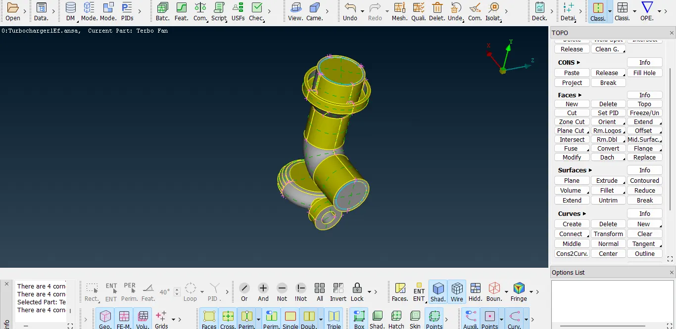
At this point the topology clean up was completed.
Assigning property IDs:
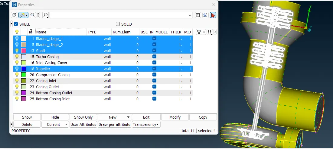
In this phase, different components were given the property IDs as follows:
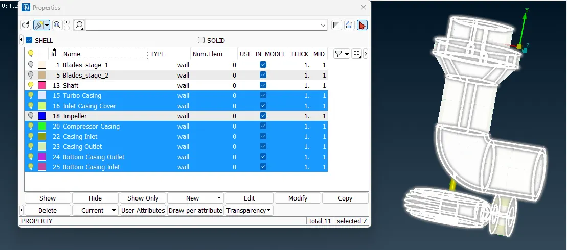
Surface meshing:
Before generating the volume mesh it is mandatory to create the surface mesh so as to assign the surface discretization parameters and later on they can be used to create the 3D mesh. Following mesh lengths were provided to the components for creating the surface mesh.
| Number | Component | Size in mm |
| 1. | Blade stage one | 2 |
| 2. | Blade stage two | 2 |
| 3. | Shaft | 2 |
| 4. | Impeller | 2 |
| 5. | Turbo casing | 5 |
| 6. | Inlet casing | 5 |
| 7. | Inlet casing cover | 5 |
To get this done the minimum and maximum length for the mesh was set in the mashing parameters and the quality parameters. Thereafter the required mesh size as listed above was given in the perimeter length and macros.
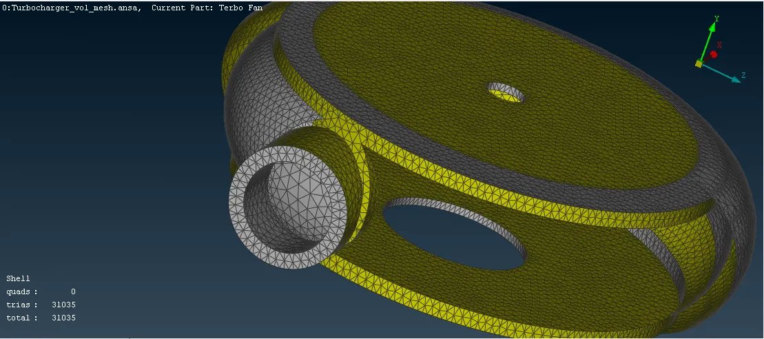
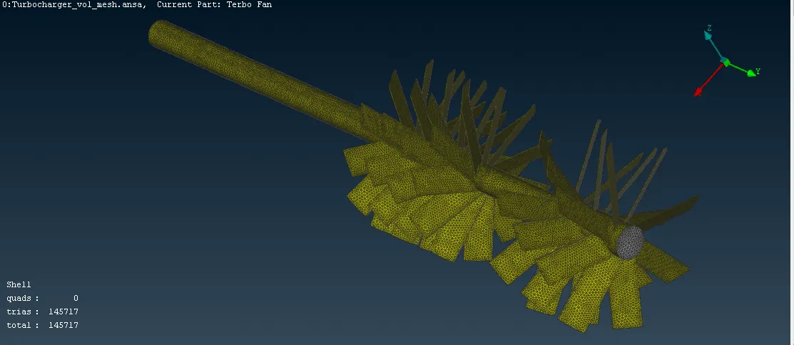
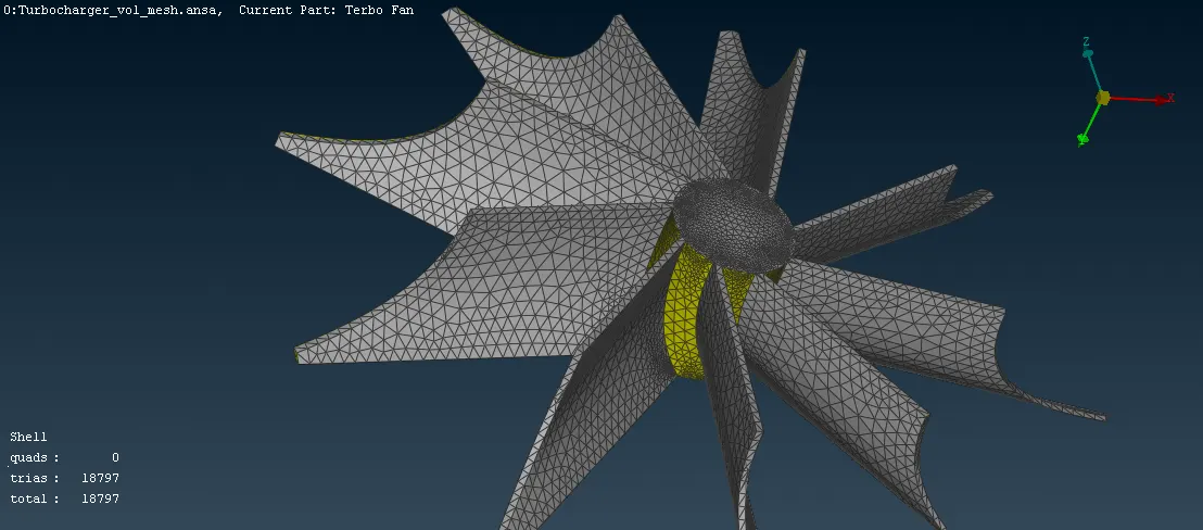
The following pictures shows the surface mesh created for various components.
Surface mesh created for the turbocharger casing:
Surface mesh created for the shaft and blades:
Surface mesh created for the impeller:
Surface mesh created for the compressor casing:
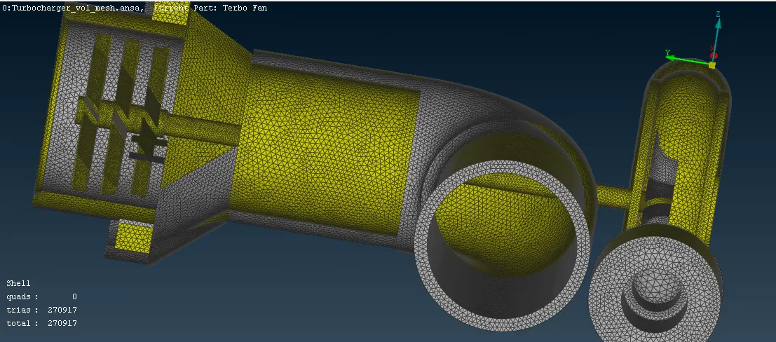
A detailed view of the turbocharger geometry with surface mesh on inner and outer regions:
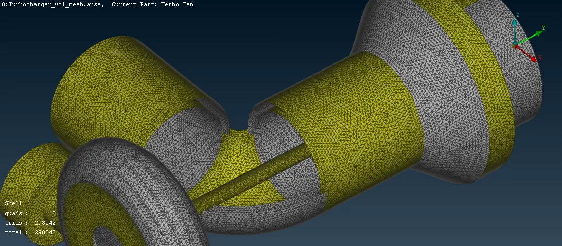
For the surface mesh roughly more than 3,00,000 triangular shell elements were created for all the visible items of the geometry.
Volume mesh:
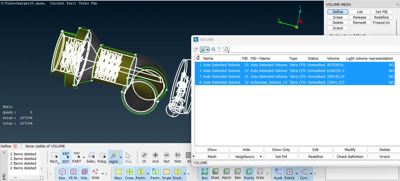
Is the surface mesh Is generated, the ANSA Automatically detected the void volume spaces and volume of components.
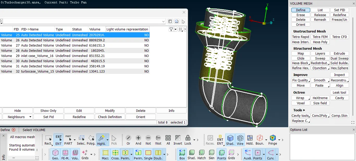
From the above auto-detected volumes, the volumes of geometries like :- compressor casing, turbo casing, blades, impeller and shaft were deleted as as the fluid is not going to flow in those regions.
For the rest of the volumes the mesh needs to be generated. These volumes include the inner space of the compressor casing having an interface with the blades and impeller, the turbocharger volume space and the outlet duct volume.
These volumes are highlighted in the below picture.
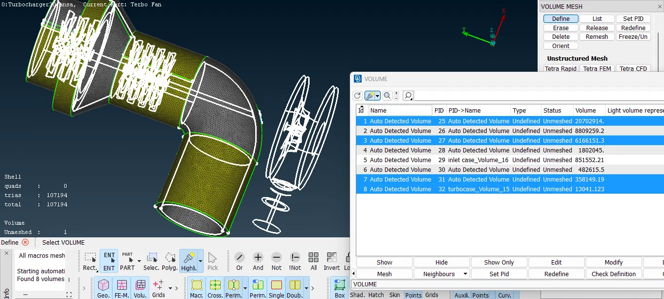
The rest of the unselected volumes are deleted. For the volumes selected, the tetrahedral 3D CFD mesh is assigned.
The following picture shows the volumetric mesh generated for the compressor casing volume. In order to visualize the mesh properly a section views created which shows the empty void space of the shaft and blades, which are not present and hence the fluid will be flowing thru this volume.
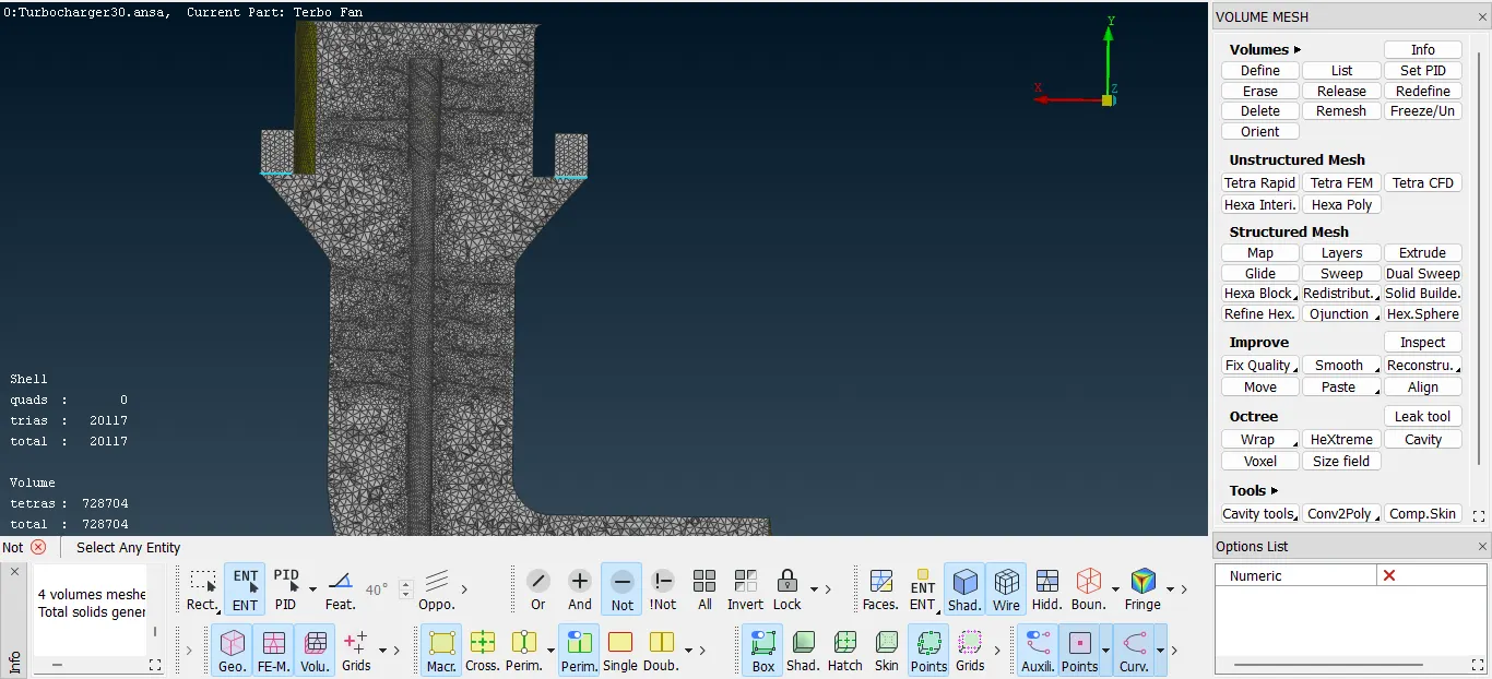
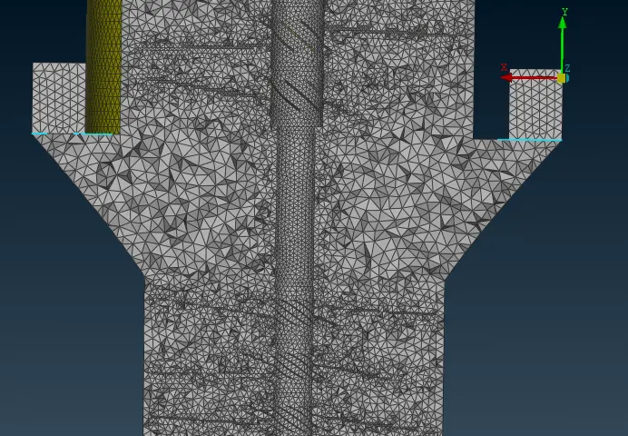
Here, nearer to the blade surface the element quality is finer as the fluid will be interacting with the blades and shaft.
The sectional view of the volumetric mesh generated for the turbocharger volume space is shown below.
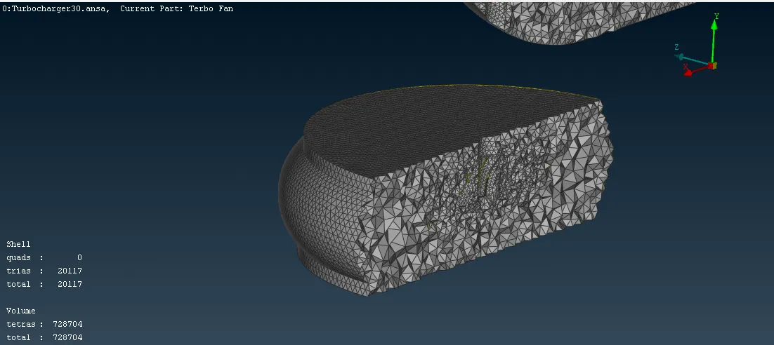
Sectional volumetric mesh view for the compressor volume space with shaft and blades, and the turbocharger volume space.
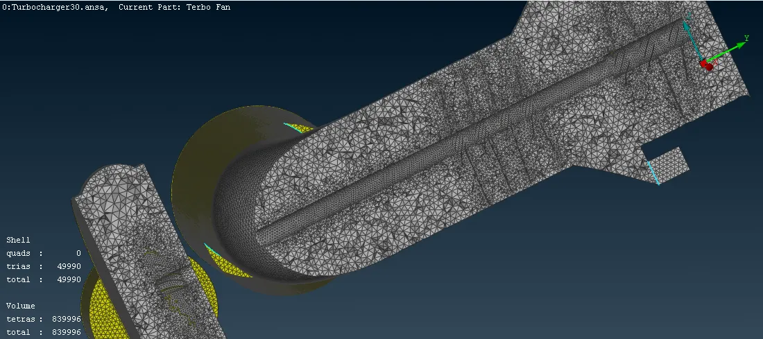
the above picture shows a sectional view of the volumetric mesh generated which has approximately 8.3e05 elements. For the entire visible geometry around 9e05 tetrahedral 3D elements were generated.