Week 3 Challenge : CFD meshing on Turbocharger
AIM:
To perform surface and volumetric mesh on Turbocharger using ANSA.
OBJECTIVES:
1. Conduct geometric error checks on the provided model to identify and rectify any inaccuracies.
2. Assign target mesh length values to each component as follows:
Blade stage-1 - 1mm
Blade stage-2 - 1mm
Impeller- 2mm
Shaft rotor- 1mm
Turbo casing- 5mm
Compressor casing- 5mm
Inlet casing cover- 5mm
3. Perform surface meshing utilizing the prescribed target lengths corresponding to the assigned PIDs.
4. Generate volumetric meshes for the required volumes.
About Turbocharger: A turbocharger is a device used in internal combustion engines to increase the power output by forcing extra compressed air into the combustion chamber. It consists of two main components: a turbine and a compressor, connected by a shaft. Turbochargers are commonly used to improve power output and fuel efficiency.
PROCEDURE:
Step 1: Geometry cleanup
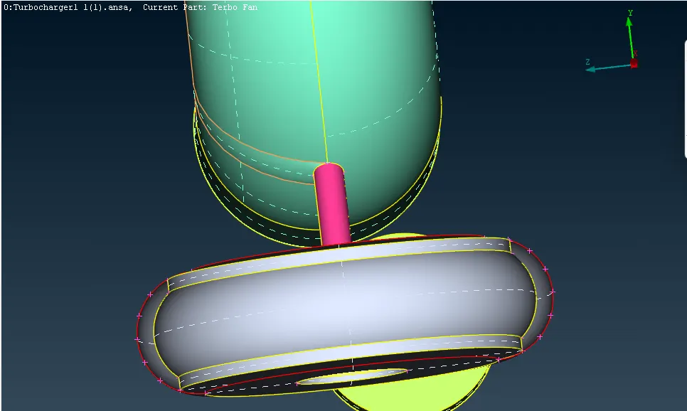
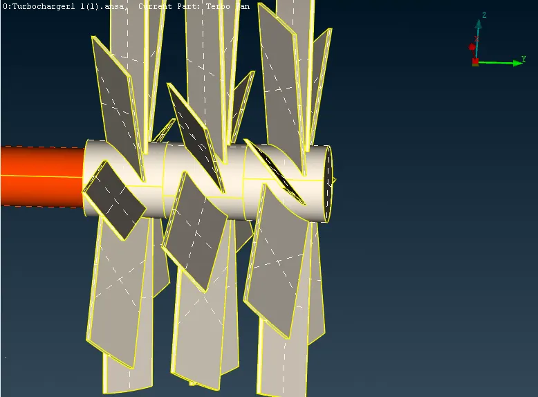
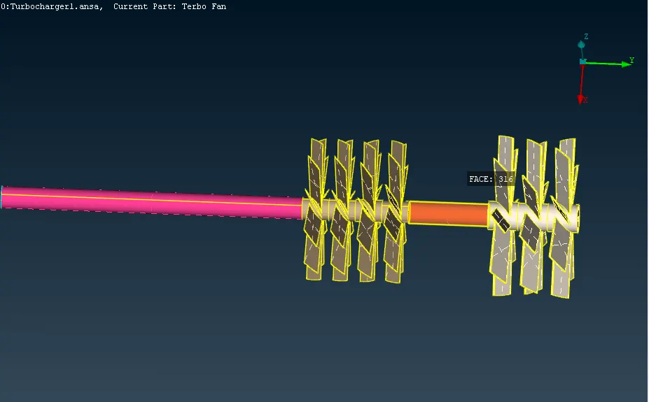
Import the turbocharger model and do geometry checks using 'checks' option. Resolve single cons and triple cons. Do topo for the entire model to identify the missing cons.
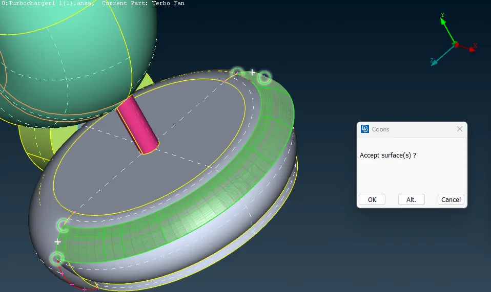
Delete overlapping surfaces utilizing the "delete" option to rectify triple cons. Employ the "new" option to add necessary surfaces, thereby converting single cons into double cons.
Project hotpoints to create curved surfaces or surfaces according to the hole.
Once again, check for single and triple cons using 'checks' option. Then move on to assigning PIDs.
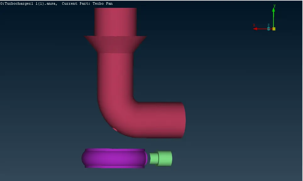
Step 2: Assigning PIDs
After completing the geometry cleanup, assign a distinct name to each PID. Additionally, customize the color of the PIDs as desired. Delete the unneccessary PIDs using compress option.
Step 3: Surface mesh
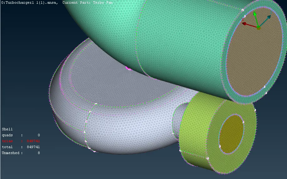
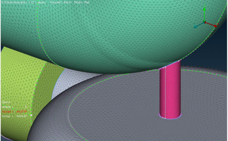
Once PIDs are assigned, initiate surface mesh creation for each component based on the specified mesh lengths. To prevent mesh erasure in connecting regions due to varying mesh lengths, commence with a larger mesh length and the do with a smaller mesh length. Ensure thorough meshing of all surfaces by zooming in and out, as some surfaces may escape during the meshing process.
Step 4: Volumetric mesh
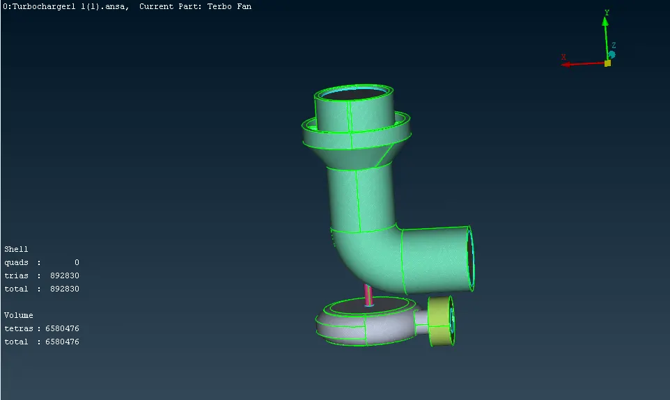
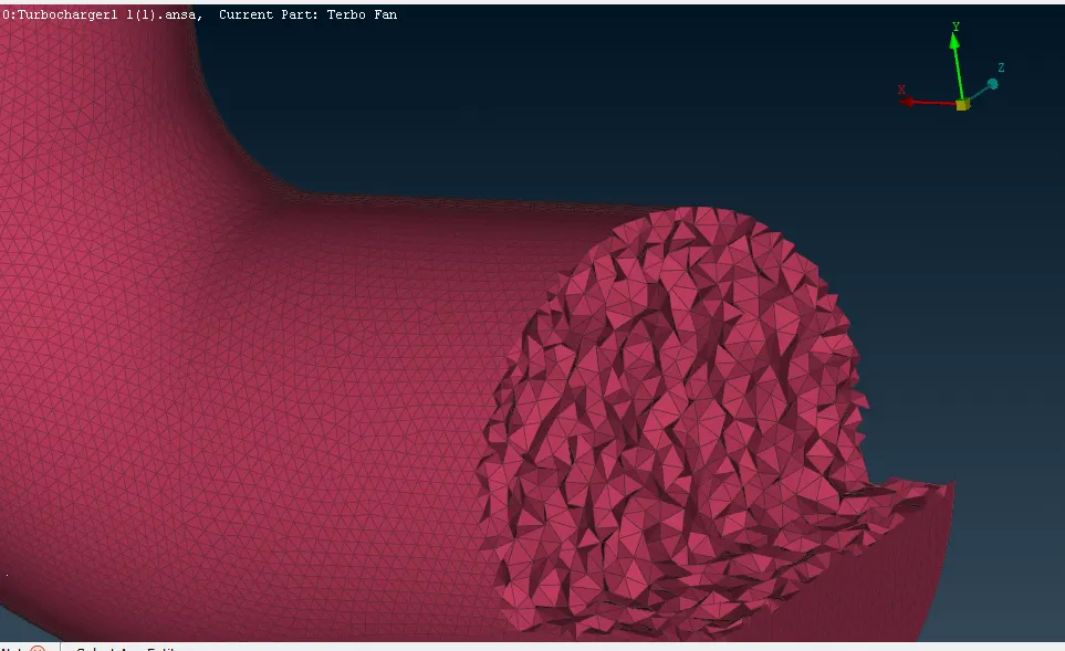
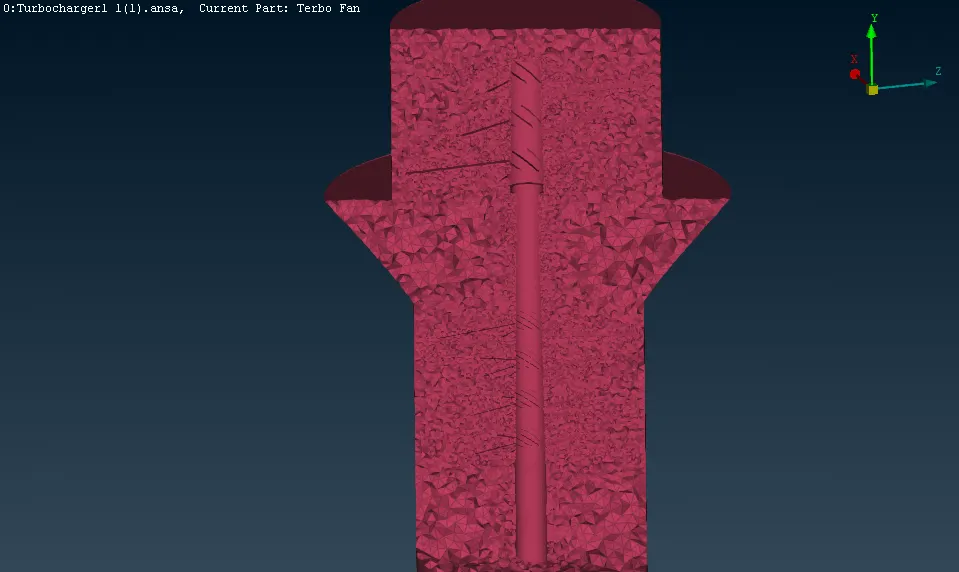
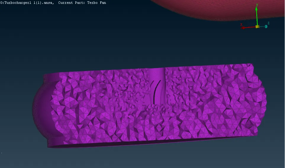
Proceed with volumetric meshing, focusing exclusively on the fluid volume region. Achieve this by removing unwanted regions and thickness of the model. Once prepared, opt for the tetra CFD option for volumetric meshing, tailored for CFD simulations. Visualize the volumetric mesh within the fluid region and use the 'not' option to hide the one half of the model, revealing the volumetric mesh inside the model.
RESULTS:
1. The geometry cleanup process has been completed for the provided model.
2. Surface meshing with varying target mesh lengths has been successfully generated.
3. Volumetric meshing for the fluid region has also been accomplished successfully.
CONCLUSIONS:
Hence, the surface meshing and volumetric meshing processes have been completed for the turbocharger utilizing ANSA software.