Week 3 Challenge : CFD meshing on Turbocharger
Objective:
The main objective of this task is to check the geometry for the error and generate the volume mesh for a given turbocharger model with the given mesh parameters.
Geometry Details and Clean-up:
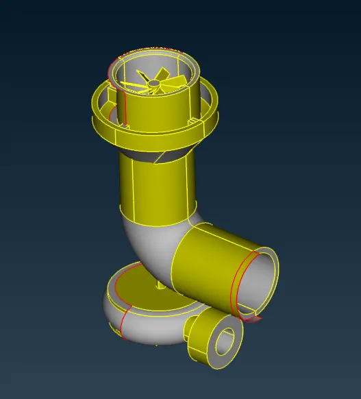
The given turbocharger model for this task is shown below:
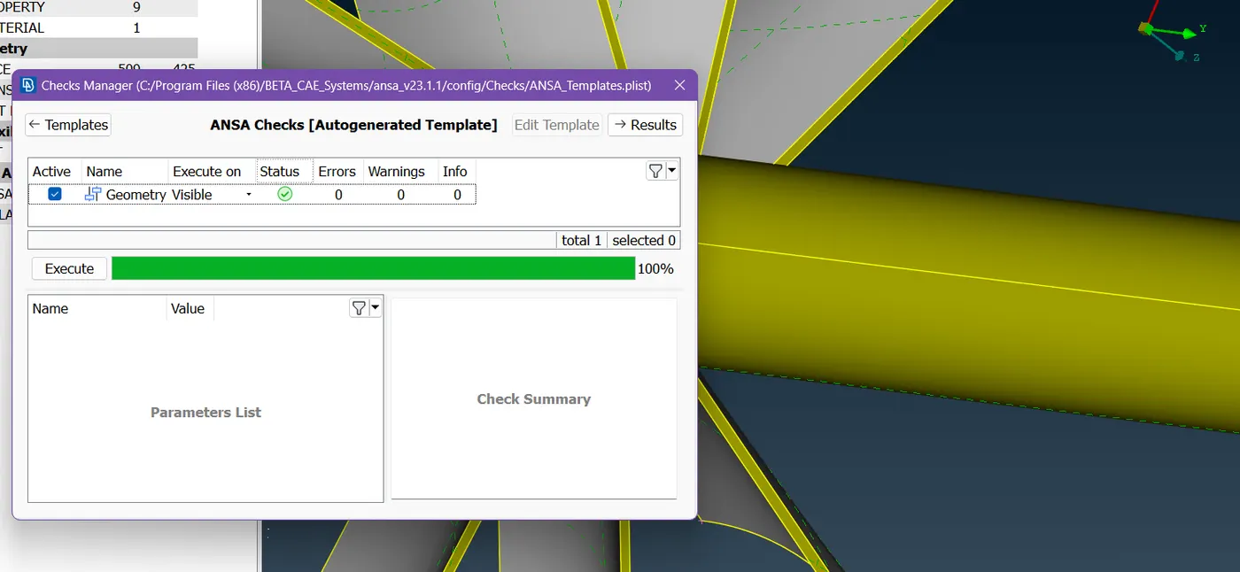
The geometry check was done for the model and single cons were found and shown in wiretunnel frame below:
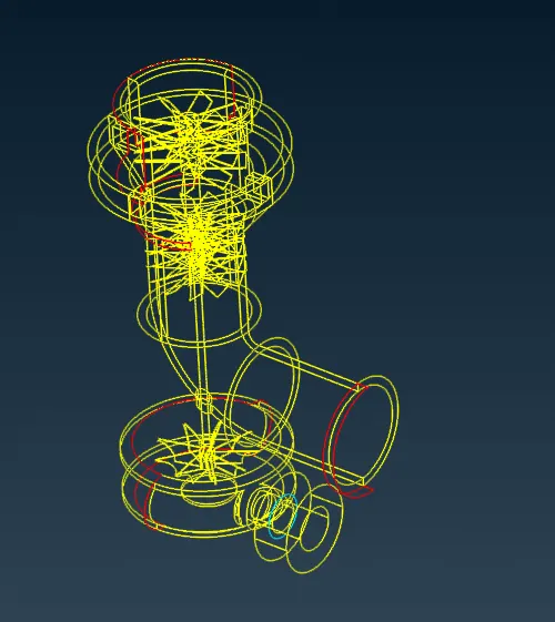
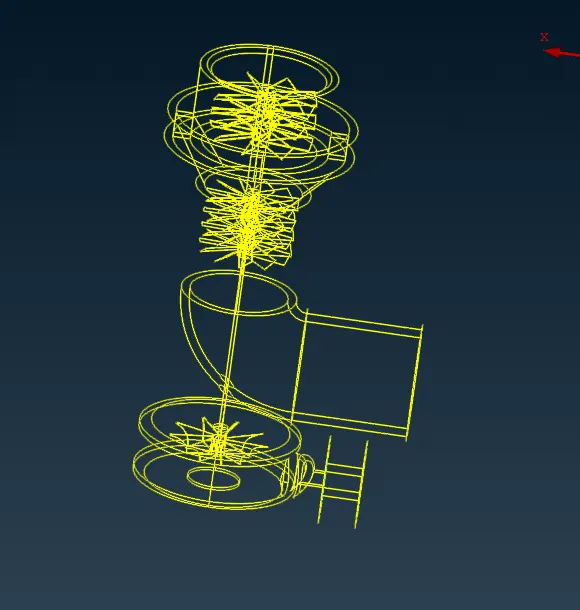
The single cons were found in multiple regions as shown above which were removed using the various options such as cons project, intersect of faces, and so on. The final cleaned geometry is shown below:
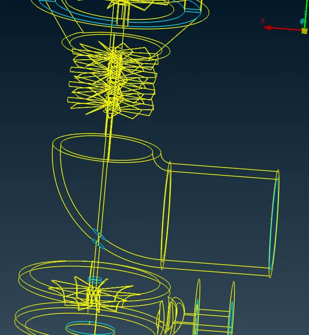
More patch-up faces were found and removed. The final model used for the surface mesh is given below:
Surface Mesh:
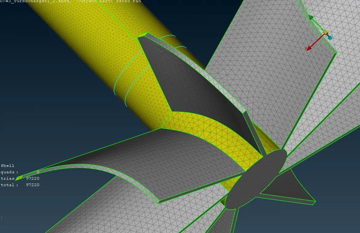
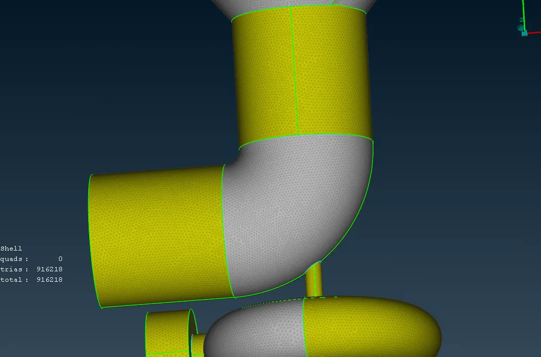
The surface mesh for the cleaned geometry was done with the given mesh parameters as:
- Blade stage-1 = 1 mm
- Blade stage-2 = 1 mm
- Impeller = 2 mm
- Shaft rotor = 1 mm
- Turbo casing = 5 mm
- Compressor casing = 5 mm
- Inlet casing cover = 5 mm
The final model with the surface mesh is shown below with the total number of tri-cells of 97220.
Volume Mesh:
- The volume mesh was created in the volume mesh module for the model following the surface mesh.
- At first, to proceed with the volume, the surface mesh is checked in the define section, showing the available unmeshed volume to be meshed.
- Except for the void/space where the volume mesh is to be created as the area of interest i.e., where the fluid flow will be considered, other detected volumes were deleted.
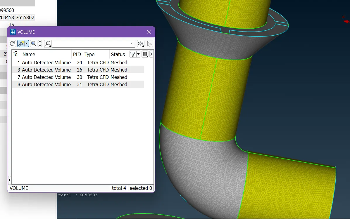
- Then, the volume cells were generated for the void regions with the Tetra-CFD type as shown below:
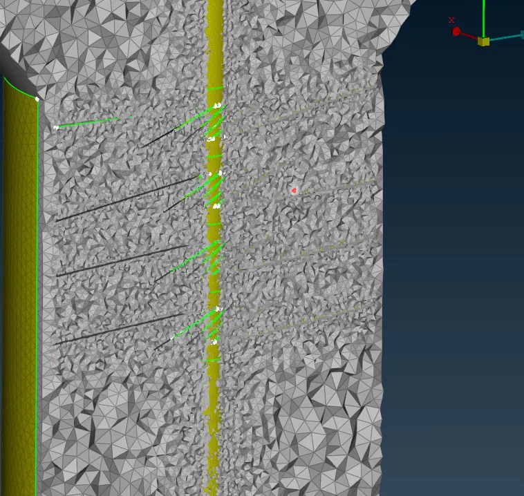
The cut section view created with NOT option of the volume cells created is shown below:
Conclusion:
- In the cut section, it is observed that the cells generated near the interface with the blade sections were small as there is a change in the mesh length for the blade sections and the turbo casing.
- The total number of volume cells created for the given turbocharger model is noted as 6.8 million (~6853235 cells).