Week 3 Challenge : CFD meshing on Turbocharger
Aim / Objective: - Perform 2D Surface mesh and thereafter execute 3D Volumetric mesh on the Turbocharger
Procedure: -
Step 1 - To Import CAD file in ANSA
- For importing the CAD Geometry go to file and click open.
- go to the directory where the cad file is present.
- select the geometry file with the .ansa extension and click open.
- After importing the geometry switch the Draw mode to PID.
- Also, enable cross Hatches and labels.
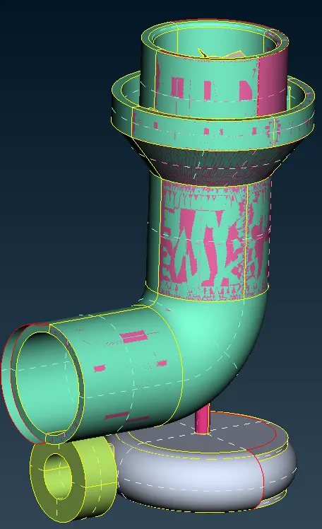
Step 2 - Geometrical Quality Check
- We can see that there are some glitches on the surface.
- These glitches indicate that there are two surfaces present over there that overlap each other.
- There may be more errors, single cons, holes, missing surfaces, overlapping surfaces, and so on in a geometry.
- Before meshing up we have to fix these errors to obtain a good mesh and a water-tight geometry.
- To perform checks, go to the checks option in the upper toolbar and select geometry in that.
- A window pops up, Select all the checks but exclude unmeshed macros because we haven't meshed the geometry yet.
- also don't select the sharp edges to check.
- After selecting the required checks click on execute.
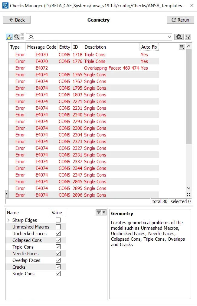
- It displays all the errors present in the geometry.
- The errors consist of Triple cons, and overlapping faces and most of them are single cons
- We need to fix these errors before moving to Meshing.
Step 3 - Topological cleanup
- First, we will delete the overlapping surface which we could see on the screen.
- select the !Not option and using the PID region method select the overlapping pink face.
- isolate this face.
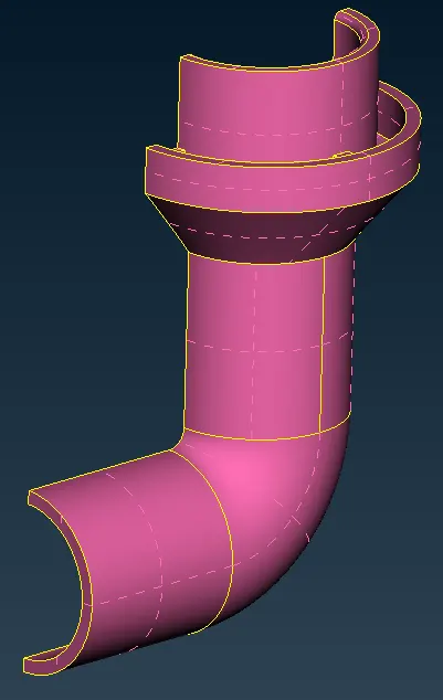
- using the delete option, delete the entire face.
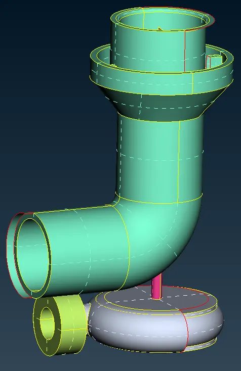
- Some part of the surface is extruded outside the geometry.
- Delete that face and we will create a new one over there.
- Click on delete and using the ENT method delete the surface.
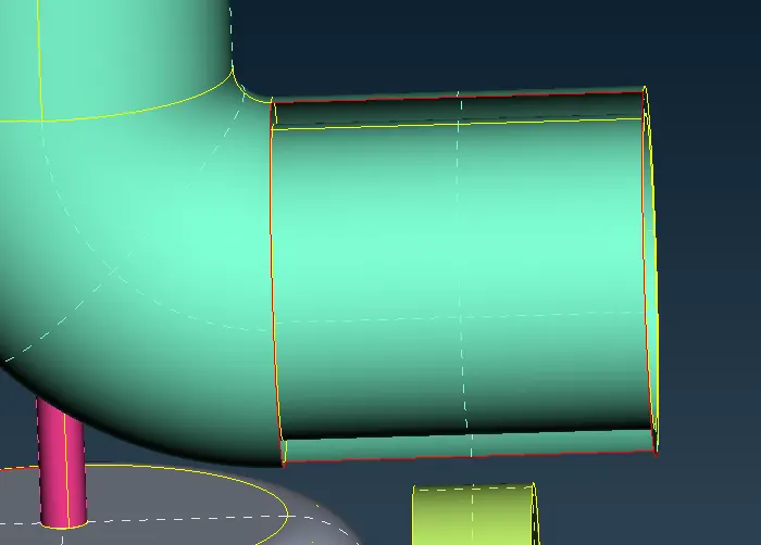
- Click on a new option under the faces section in the Topo deck.
- A window pops out, Select coons option.
- Using the Loop method select the single cons and create a new surface.
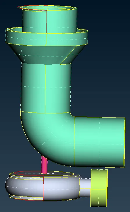
- At first the surface we had deleted because of which a void has been created which led to the generation of single cons.
- We have to fix it by creating small faces.
- Project the bottom hot points on the top single cons.
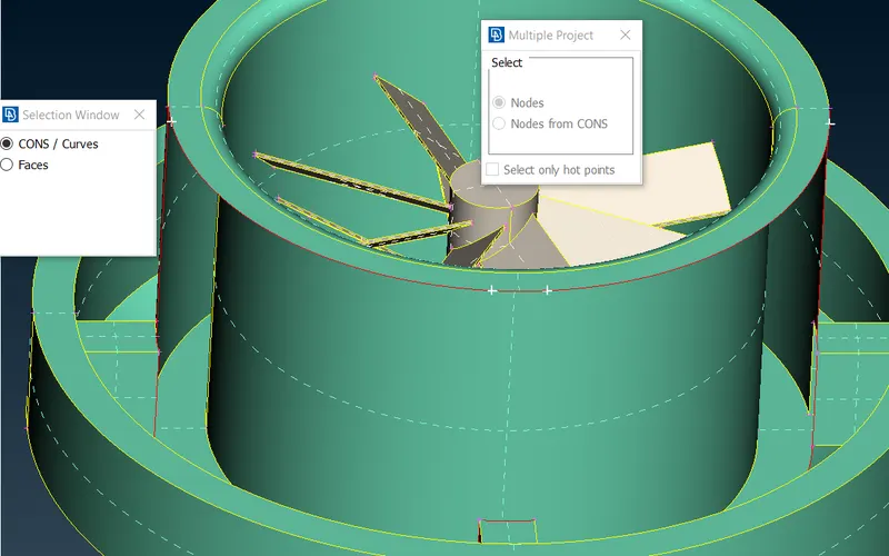
- Now using Coons option create surfaces one by one.
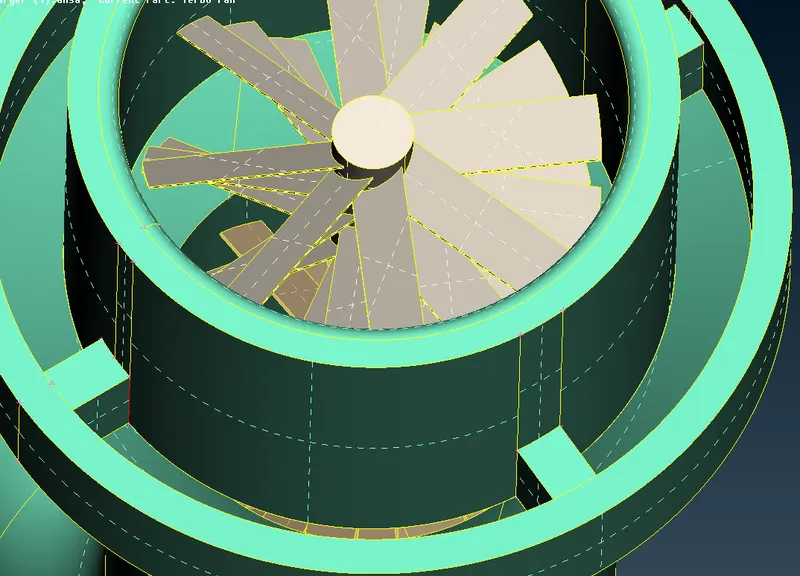
- We can see that, in there is some gap between the surface through which we can see the blades.
- We can fix these by creating surfaces using coons option to seal that passage.
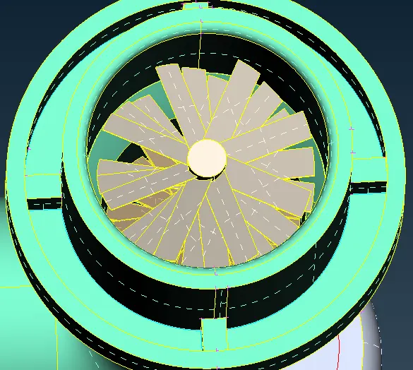
- We can see that there is a single con present which we can solve using the Topo option.
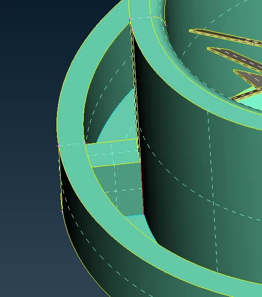
- Click on the topo option under the faces section under the topo deck.
- select the con using the box select and do a middle click to solve the error.
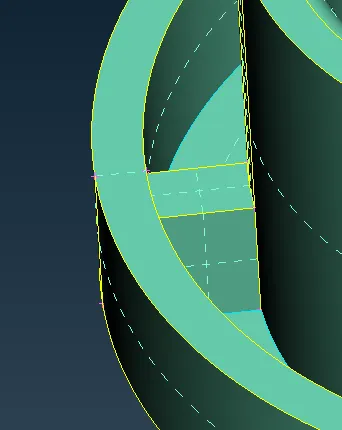
- The topo option is used to combine the Cons present which are not joined together by default.
- At the bottom, we can see we have some single cons and the geometry is broken.
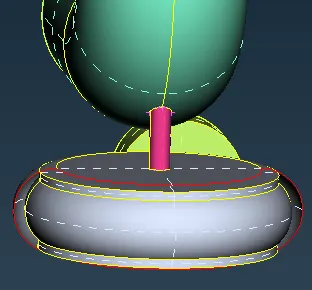
- Now here we have to create hotpoints first on the single cons and then generate the whole face part by part.
- To create the hot points click on parametric under the hotpoints section in the Topo deck.
- A window pops up, insert a 0.5 value and select the direction by clicking on the single cons in the direction we want the hotpoint to be placed.
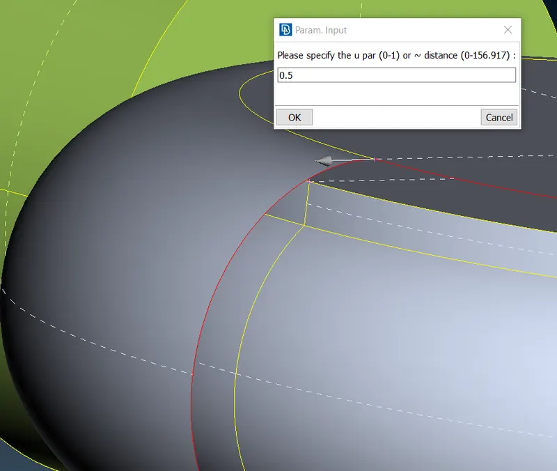
- It considers the length of the con to be 1 so by inserting a value of 0.5 it creates the Hotpoint in the middle.
- The arrow displays the direction chosen.
- Do a middle click to confirm and generate 6 more hotpoints.
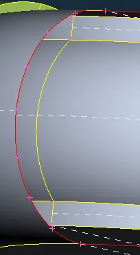
- Do the same on the other side of the geometry.
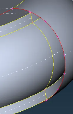
- Now create new surfaces using the new option under the faces section under the TOPO deck
- A window pops up, select the coons option, and using the ENT method create the surface.
- Click on the alternate option to choose the best surface.
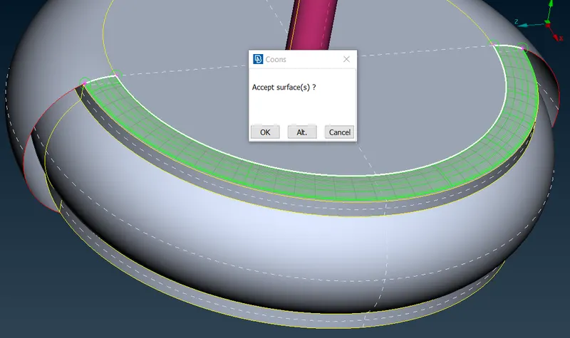
- Repeat the same for other single cons and complete the whole surface.
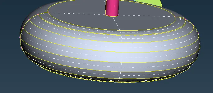
- Now, if we do a geometry check now, we can see there are some single cons present in the top geometry.
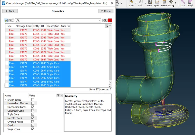
- Select all the single cons and right-click on them.
- Now select the show-only option.
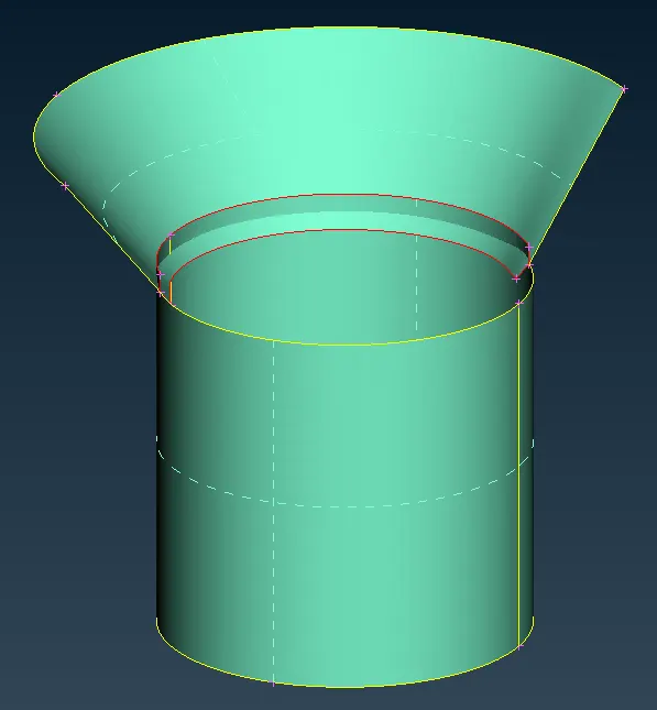
- We can see that two surfaces penetrate each other.
- So now we have to break the extra unwanted portion and delete it.
- Click on intersect option under the faces section in the TOPO deck.
- A window pops up, select the first surface and do a middle click.
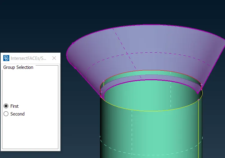
- Now select the second surface and do a middle click.
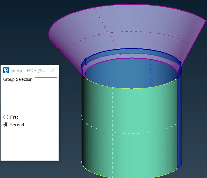
- A window pops up, click on keep, to keep all the faces.
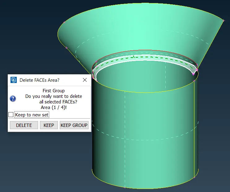
- Now, using the delete option select the unwanted surfaces.
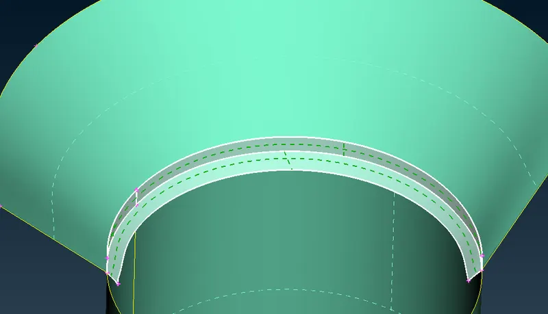
- Now do a middle click to delete the surfaces.
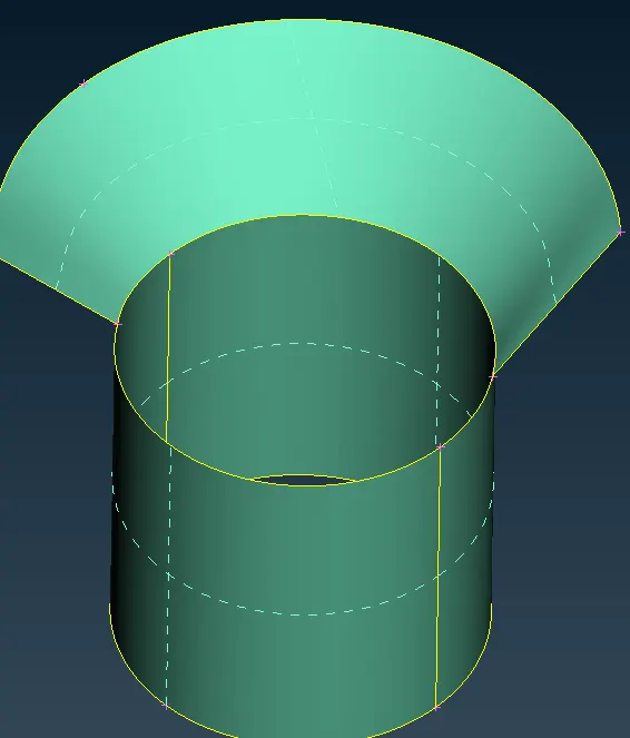
- Click on the ALL option to display all the components.
- Now we have to inspect the inside components.
- Using the Not option and PID region method hide other bodies.
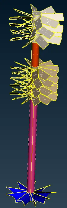
- Lock the view.
- We can see some glitches on the surface.
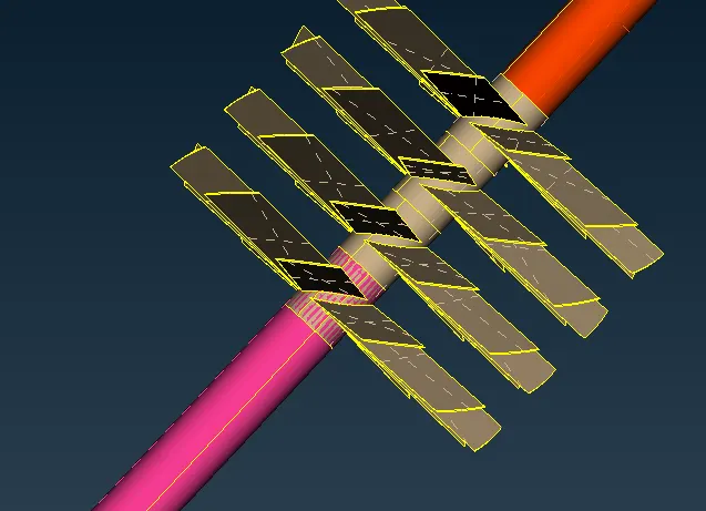
- that means there is some overlapping surface present over here.
- To delete the pink overlapped surface, we first have to separate the surface from its parent.
- To do so we will use the project option.
- Click on the project option under the Cons section in the TOPO deck.
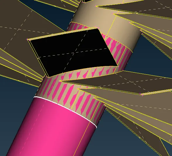
- Select the Cons and do a middle click to confirm it.
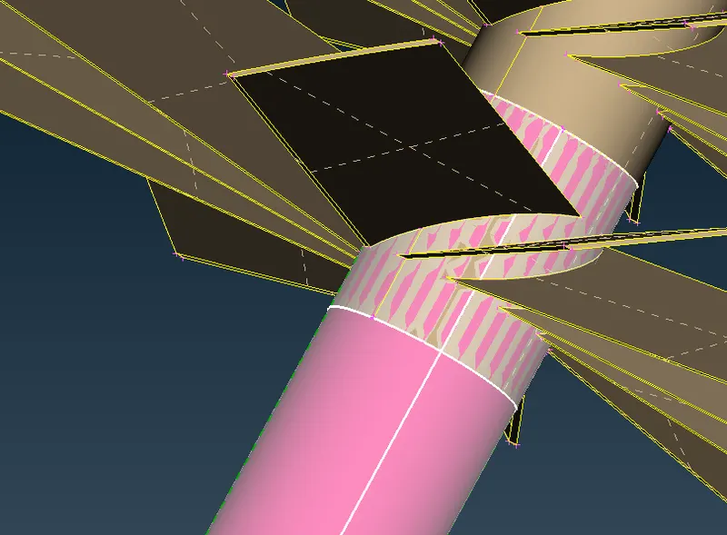
- Now select the face on which we have to project the cons and do a middle click to confirm the selection.
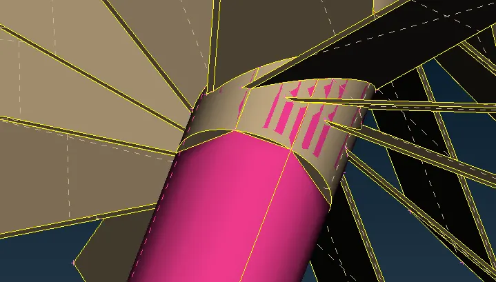
- Now we can see that the surface is separated but, the resolution of the new cons is less.
- To improve the resolution, click on the fine option under the Auxiliaries section in the TOPO deck
- Do multiple clicks on the face to improve the resolution.
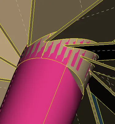
- Do the same for other surfaces.
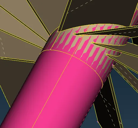
- Now, we can delete the overlapped surface using the delete option.
- Select the delete option and click on the crosshatch of the pink surface.
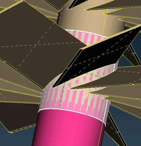
- Click middle to confirm the selection and delete the surfaces
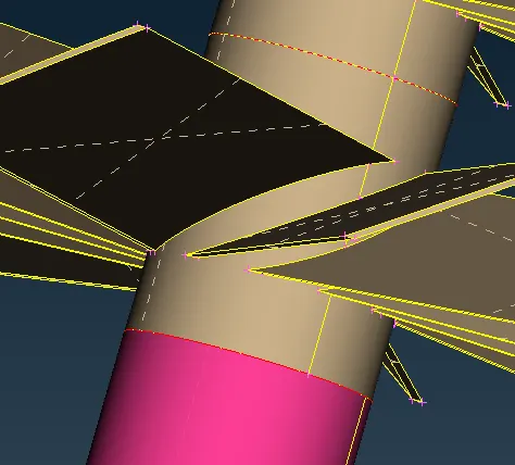
- Now, a single con is formed, and we can solve it using the TOPO option.
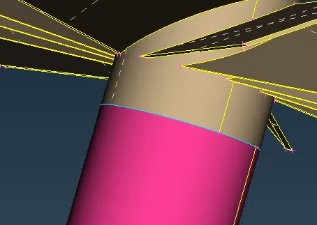
- After using the Topo option, a triple con is formed, which means there is a third surface present.
- If we hide the pink color surface, we find there is another face inside.
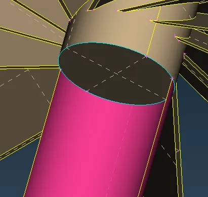
- We will delete this face since it is not required and we want a double con here.
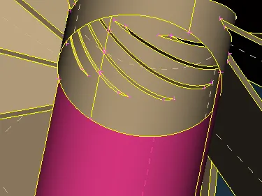
- Click on ALL.
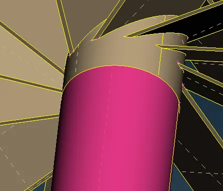
- Now we have the desired double con here
- There are many more such cases in this geometry we will have to fix those as well.
- Starting from the top, if we hide the surface, we can see there are other surfaces in it.
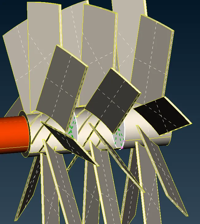
- We will delete those as well.
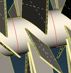
- After deleting those surfaces single cons are formed which we can fix by using the Topo option under the faces section in the TOPO deck
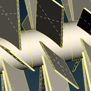
- Now again there is an overlapping surface that we can see when we hide this surface.
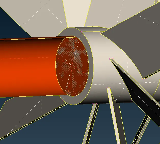
- We will delete the orange overlapping surface using the delete option.
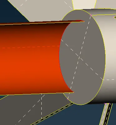
- Now we need to delete the grey surface but we want to delete only the part which is inside the cons of the orange surface.
- To do so we will project the orange surface cons onto the grey surface.
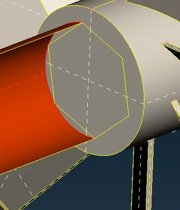
- But the projected cons have low resolution.
- We can increase the resolution using the fine command from the auxiliaries section under the TOPO deck.
- After making it fine we can delete that surface using the delete command.
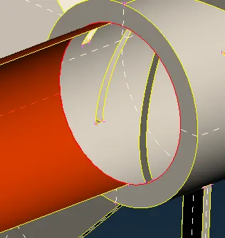
- Now we can fix the single cons using the Topo option from the faces section under the Topo deck.
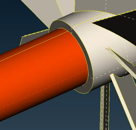
- In the other direction, we encounter the same problem which we solve using the same method.
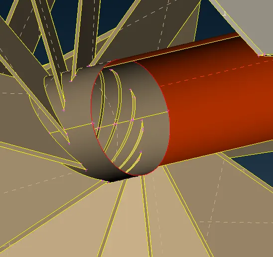
- We get rid of these single cons using the Topo option.
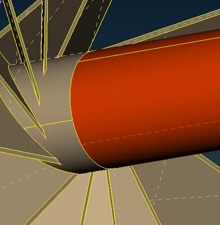
- We can see that there is another triple con present which means there is a third surface.
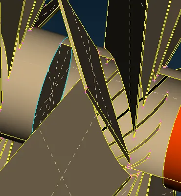
- We will delete this surface using the delete option and use the topo command to resolve the errors.
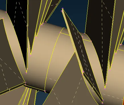
- Besides this con, if we hide the surface, we can see another surface present.
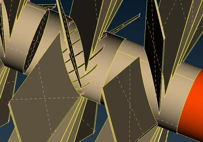
- We will delete this surface and solve the errors.
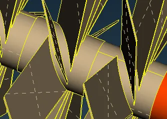
- There is con with glitch present which means there is an overlapping surface over there.
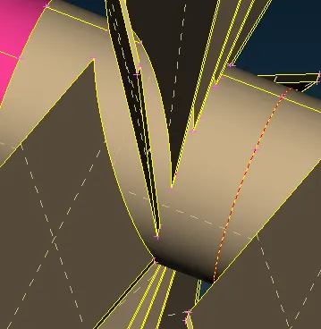
- If we hide the surface, we can see that there is a pink and grey color surface present.
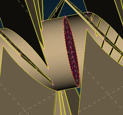
- we will delete both this surface and solve the errors.
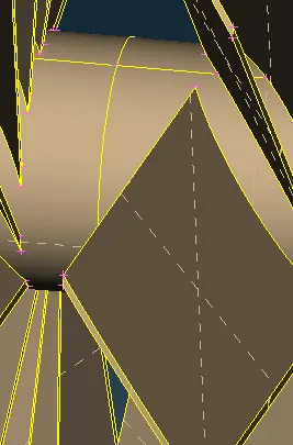
- t the bottom, we have an overlapping surface.
- we will delete the overlapping surface.
- We will perform the Topo to solve any errors.
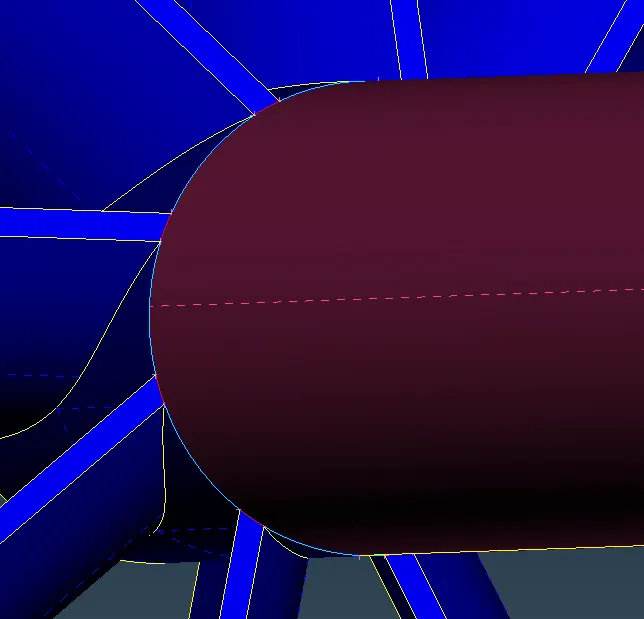
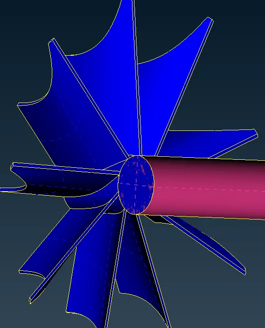
- We will also need to delete the blue surface but it is connected with its neighbor surface.
- So, we need to break the contact by creating new cons.
- we will project the pink surface Cons onto the blue surface.
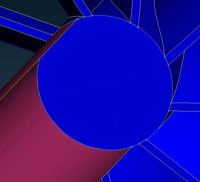
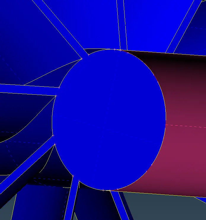
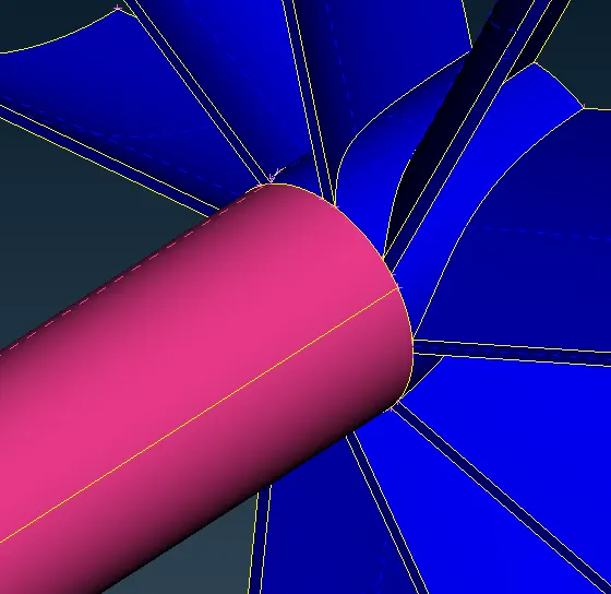
- After projecting the cons, we can see that the inner surface is disconnected from its Neighbour.
- Now we can delete it without affecting other surfaces.
- Delete the surface and perform the topo command on it to resolve any errors.
- To be sure that we have solved all errors regarding the inner components let's perform a geometry check.
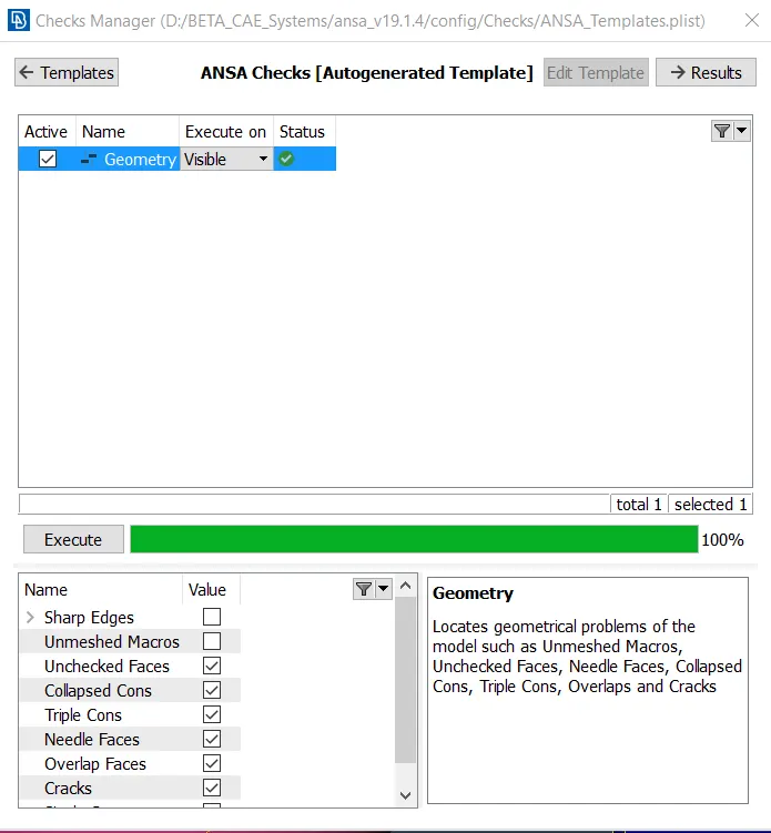
- We can see that there are no errors in this geometry.
- Now we will exit the lock mode and make all components visible.
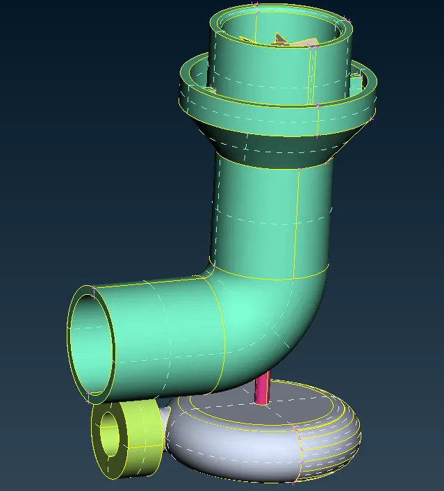
- At the bottom, if we hide these surfaces then we can see that there are overlapping surfaces present.
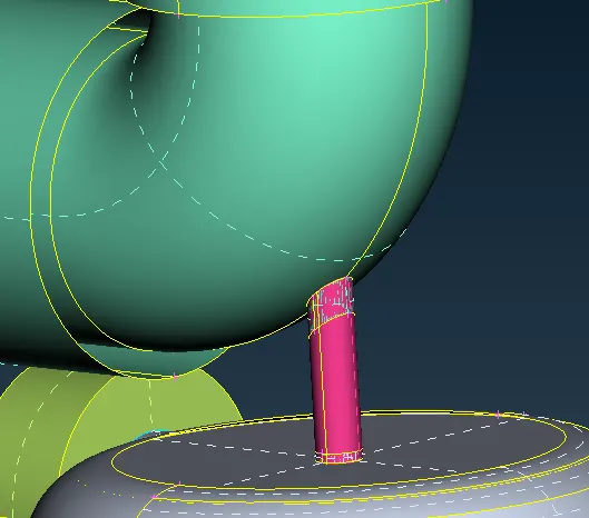
- We will delete this using the delete option.
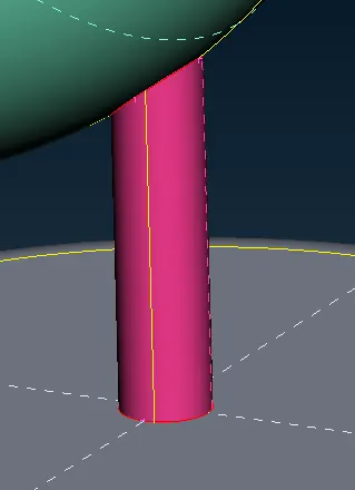
- We can see that single cons are generated here which are not solved by the Topo option as well.
- So, we have to project cons onto the pink surface and then do Topo.
- To project click on the project option under the cons section in the TOPO deck
- We select the cons precisely by turning off the shadow mode.
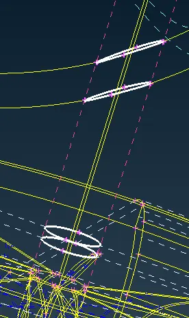
- After selecting the cons do a middle click to confirm it.
- Now select the surface.
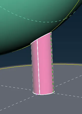
- Do a middle click to confirm it and the cons will be projected onto the pink surface.
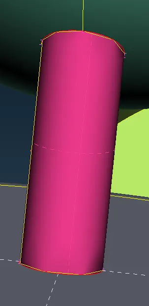
- We can see that the resolution of the new cons is low we can make it finer with the help of fine option under auxiliaries section in topo deck.
- After making it fine we will use the Topo option to solve the errors.
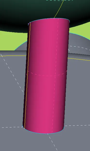
- Since these cons are used by three surfaces a triple con is created over there and is not an error.
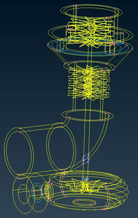
- Now if we turn off the shadow mode, we can see that there are triple cons present but we will need these triple cons as they are shared by three surfaces and we can delete any of it.
- Now we have to close any opening to make the geometry watertight.
- By clicking on new option from faces section under topo deck create a new surface using coons option.
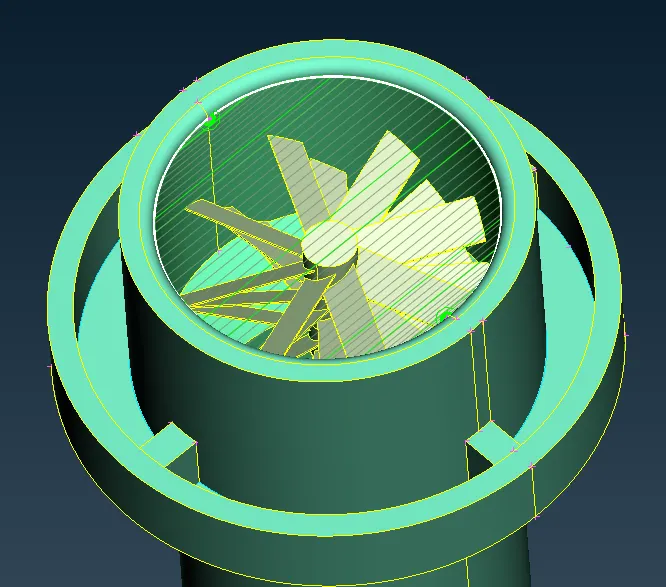
- Again, in the bottom do the same
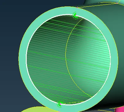
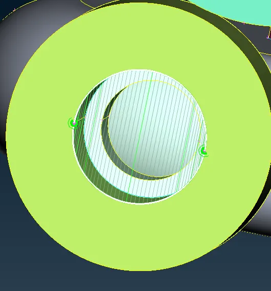
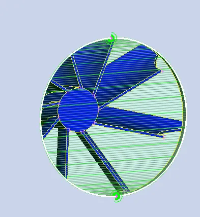
Step 4 - Assign PID
- We have to assign PID to each component in the model.
- There is an option PID manager in the top toolbar.
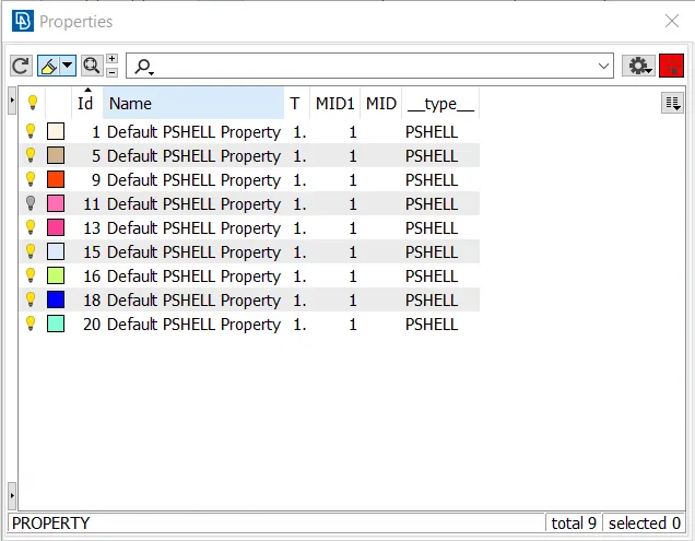
- Since the PIDs are already assigned we will have to rename them.
- Also, for the inlet and outlet, we have to create a new PID.
- To create PID, right-click in the window and click on new and select PSHELL in that again select PSHELL.
- A window pops out in that type the name of the component
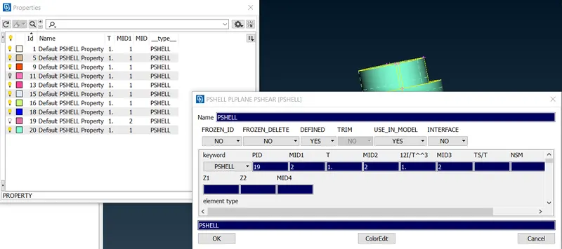
- Now create the PID for Casing Inlet, Casing Outlet, Bottom Casing Inlet, and Bottom Casing Outlet.
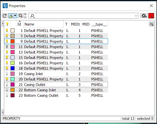
- Now we have to assign them to their respective surfaces.
- Right-click on Casing Inlet and select Apply.
- Select the casing inlet and do a middle click to confirm it.
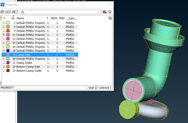
- Right-click on Casing Outlet and select Apply.
- Select the casing Outlet and do a middle click to confirm it.
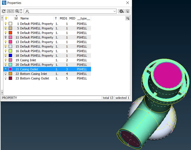
- Right-click on Bottom Casing Inlet and select Apply.
- Select the Bottom Casing inlet and do a middle click to confirm it.
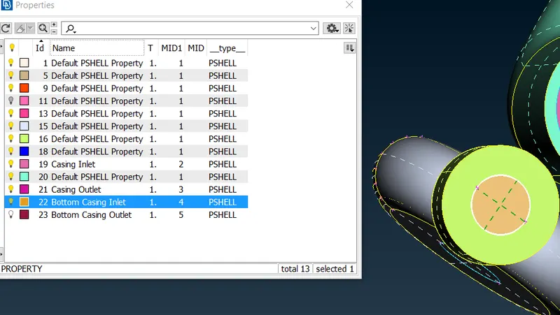
- Right-click on Bottom Casing Outlet and select Apply.
- Select the Bottom Casing Outlet and do a middle click to confirm it.
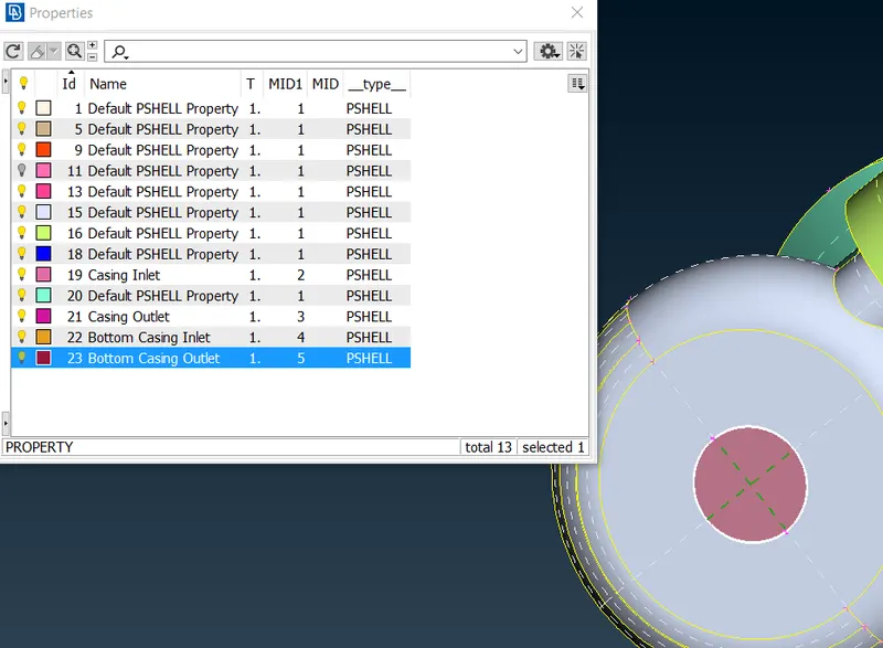
- Now we will rename the remaining PIDs as Blades Stage_1, Blades Stage_2, Shaft rotor, Turbo casing, and Inlet casing
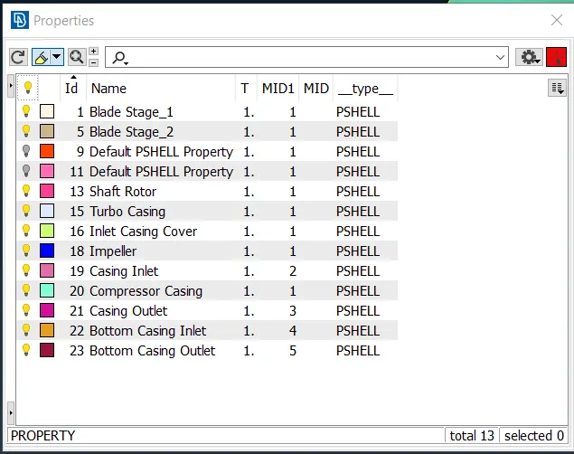
- here we can see that there are two PIDs that are not present in the geometry.
- we have to force delete these PIDs
- to force delete click on the compress option in the top toolbar.
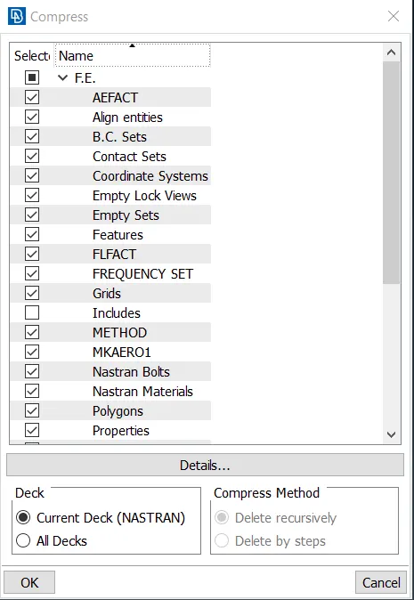
- Click on OK to delete/ compress the unwanted PIDs.
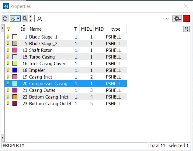
- We can see that the unwanted PIDs are gone, i.e. deleted.
- Now we are done with assigning the PIDs and will move forward to the surface meshing of the components.
Step 5 - 2D Surface Meshing
- To perform 2D surface meshing we will switch to the Mesh deck.
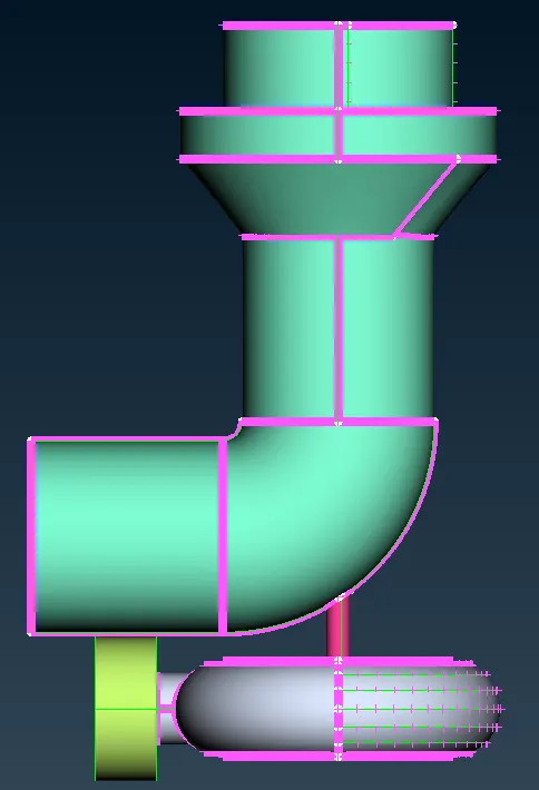
- We will have to mesh each component individually with different target lengths as the size of each component differs and we want to capture the geometry very well.
- We will first mesh the Turbo casing, compressor casing, and inlet casing cover as well as their inlets and outlets with 5mm as the target length.
- We are meshing these components with 5mm as they are large enough to have 5 mm mesh and 5mm mesh will be able to capture this geometry effectively.
- As the mesh length is 5mm for these elements we will mesh them together.
- We will keep only the Turbo casing, compressor casing, inlet casing cover, and their inlets and outlets on our screen and hide all other entities using the PID manager.
- To hide the PID click on the bulb symbol. When the bulb is glowing, it means that the entity is visible and when it is off it means that it is hidden.
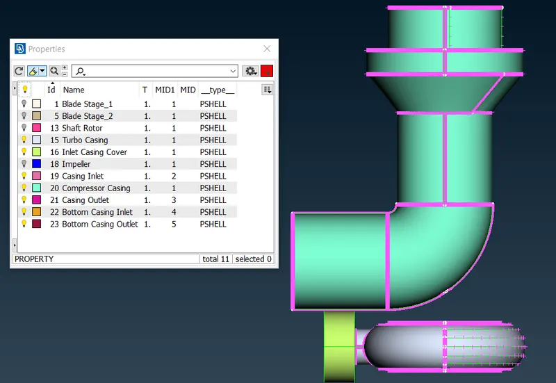
- Open the quality criteria by clicking on the option in the upper toolbar.
- Enter the min length as 3 and max length as 7.
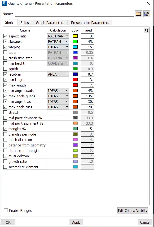
- Click on OK and open the mesh parameters from the upper toolbar.
- Select the general mesh of Tria elements of 1st order and insert the target length as 5, minimum target length as 3, and maximum target length as 7.
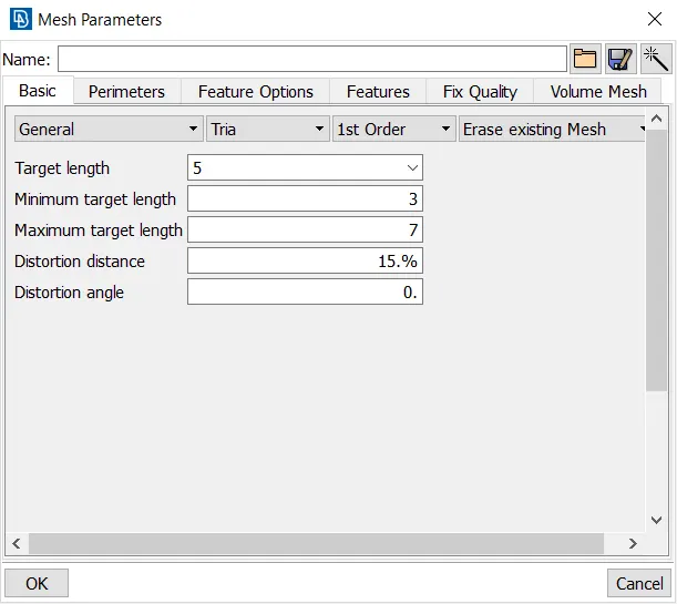
- Click on Ok.
- Now click on the length option in the Perimeter section under the Mesh deck.
- A window pops up, in that choose the Perimeters option and select all the visible entities using box select.
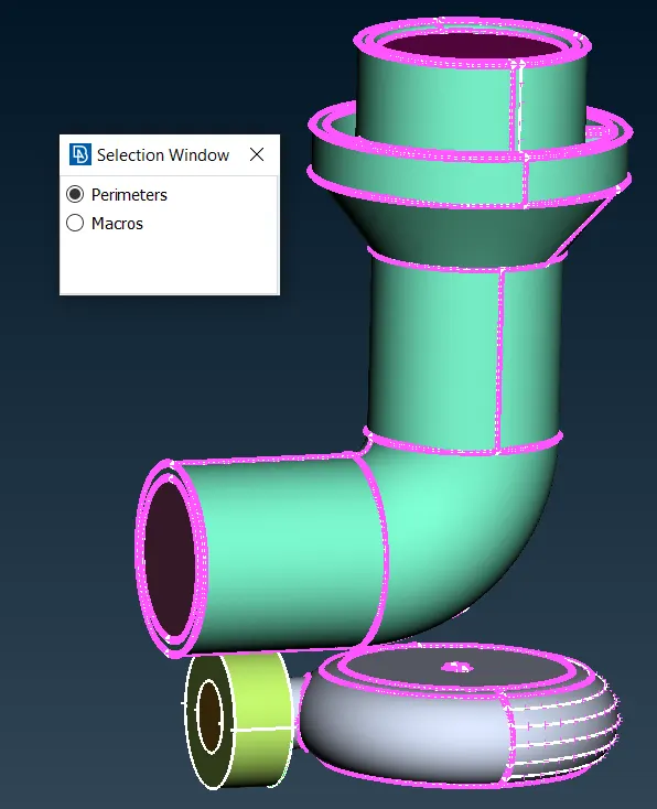
- Do a middle click to confirm the selection.
- Another window pops in that insert the length as 5.
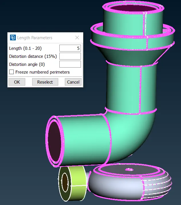
- Click on OK.
- Now select the macros option in the window.
- Select all the entities on the screen using the box select.
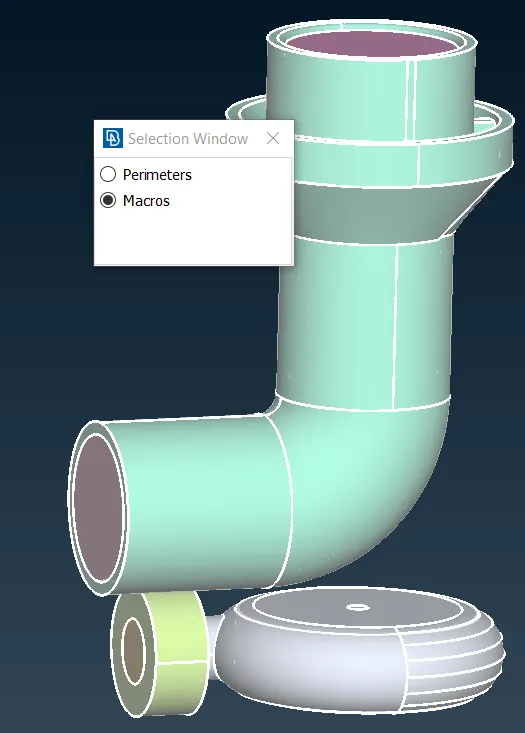
- Do a middle click to confirm the selection.
- Now a new window pops up, insert the length as 5.
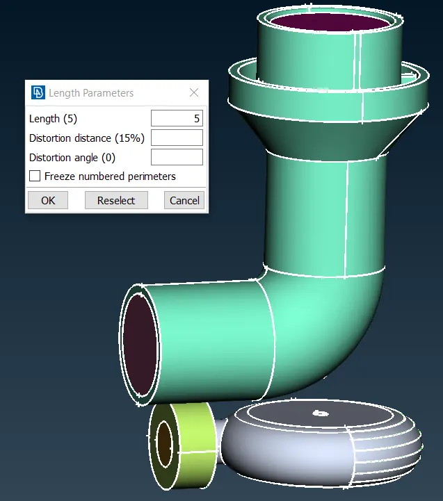
- click on Ok.
- now click spot mesh under the mesh generation section in the Mesh deck.
- elect all the faces using the box select.
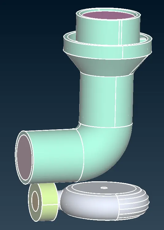
- Do a middle click to confirm the selection and generate the mesh on these faces.
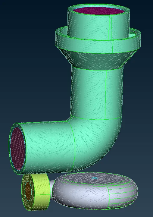
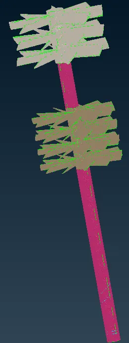
- Now we will mesh the Blade stage-1, Blade stage-2, and the Shaft rotor.
- Since these are small in size, we will mesh them with a 1mm mesh length, as a 1mm mesh length will be able to capture this geometry effectively.
- Hide all other PIDs and only enable the Blade stage-1, Blade stage-2, and the shaft rotor in the PID manager.
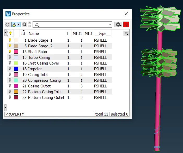
- Now open the quality criteria from the upper toolbar
- Insert the min length as 0.5 and the max length as 2
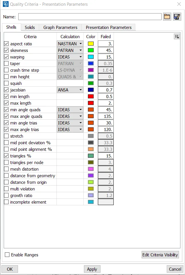
- Click on OK and open the mesh parameters from the upper toolbar.
- Select the general mesh of Tria elements of 1st order and insert the target length as 1, minimum target length as 0.5, and maximum target length as 2.
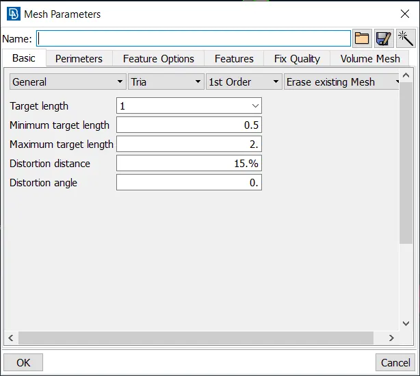
- Click on Ok.
- Now click on the length option in the Perimeter section under the Mesh deck.
- A window pops up, in that choose the Perimeters option and select all the visible entities using box select.
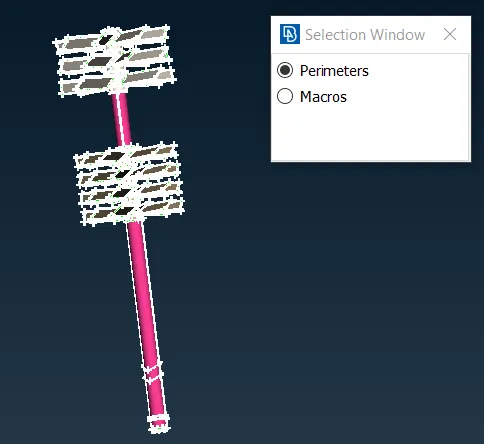
- Do a middle click to confirm the selection.
- Another window pops, in that insert the length as 1.
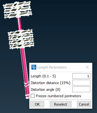
- Click on OK.
- Now select the macros option in the window.
- Select all the entities on the screen using the box select.
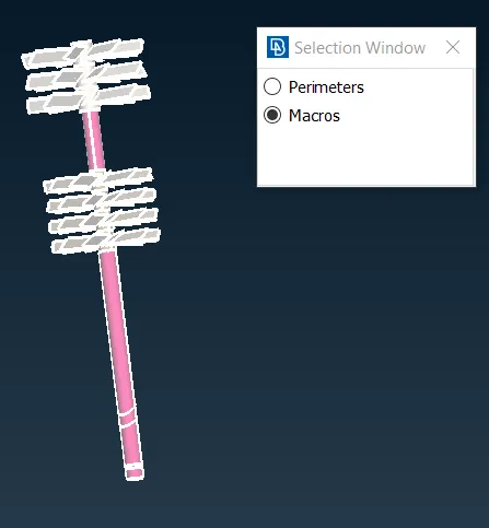
- Do a middle click to confirm the selection.
- Now a new window pops up, insert the length as 1.
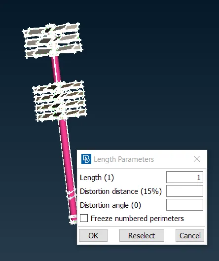
- Click on Ok.
- Now click spot mesh under the mesh generation section in the Mesh deck.
- Select all the faces using the box select.
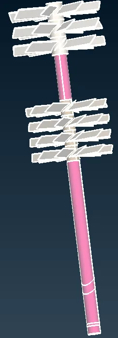
- Do a middle click to confirm the selection and generate the mesh on these faces.
- Now we will mesh the remaining component which is the impeller.
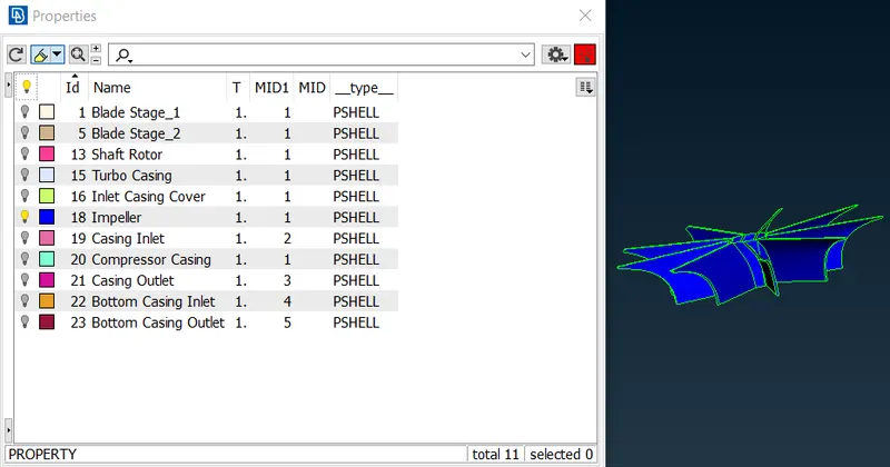
- Since it is also small in size, we will mesh it with a 2mm mesh length, as a 2mm mesh length will be able to capture this geometry effectively.
- Hide all other PIDs and only enable the Impeller in the PID manager.
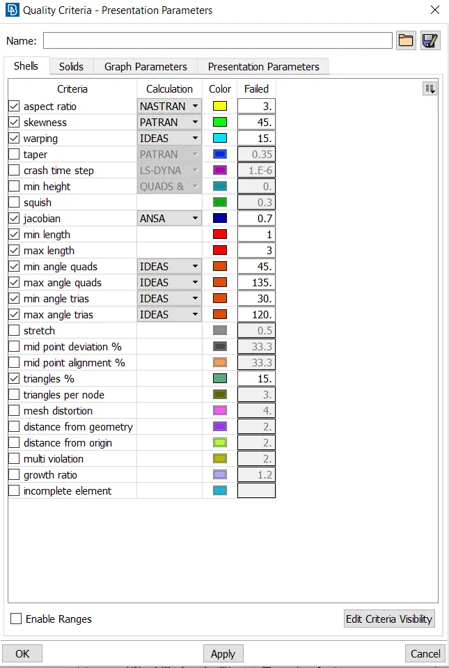
- Now open the quality criteria from the upper toolbar
- Insert the min length as 1 and the max length as 3
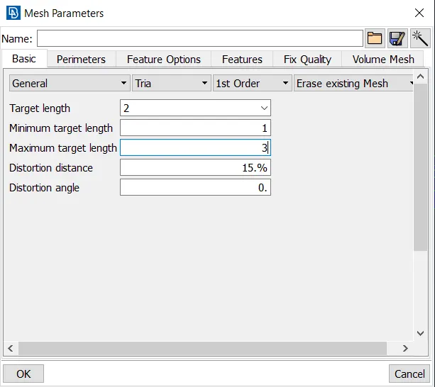
- Click on OK and open the mesh parameters from the upper toolbar.
- Select the general mesh of Tria elements of 1st order and insert the target length as 2, minimum target length as 1, and maximum target length as 3.
- Click on Ok.
- Now click on the length option in the Perimeter section under the Mesh deck.
- A window pops up, in that choose the Perimeters option and select all the visible entities using box select.
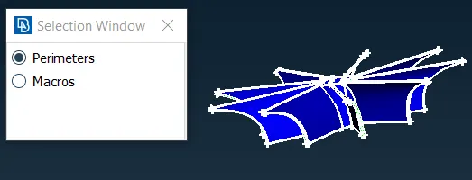
- Do a middle click to confirm the selection.
- another window pops in that insert the length as 2.
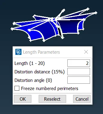
- Click on OK.
- Now select the macros option in the window.
- select all the entities on the screen using the box select.
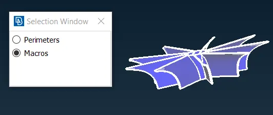
- Do a middle click to confirm the selection.
- Now a new window pops up, insert the length as 2.
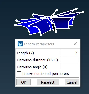
- Click on Ok.
- Now click spot mesh under the mesh generation section in the Mesh deck.
- Select all the faces using the box select.
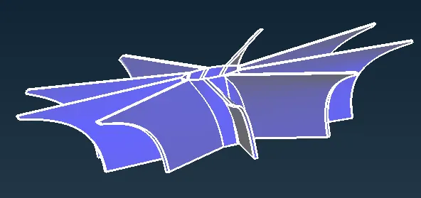
- Do a middle click to confirm the selection and generate the mesh on these faces.
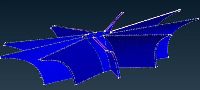
- Make the shaft rotor visible using the PID manager.
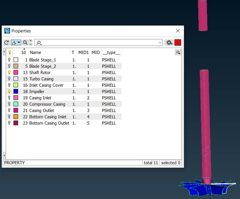
- We can see that the mesh is erased at the shaft near the impeller.
- This is because the mesh length of 2mm and 1mm are meeting at a common edge, as it is the transform from 2mm to 1mm.
- We have to mesh that part again with a 1mm mesh length.
- We will insert the min length as 0.5 and the max length as 2 in the quality criteria.
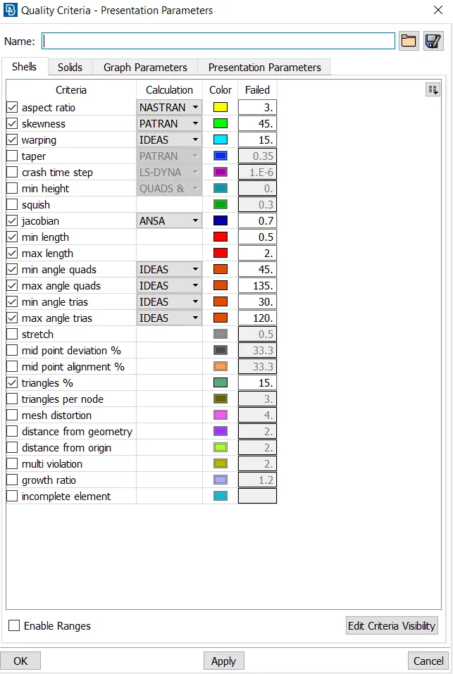
- Click on OK and open the mesh parameters from the upper toolbar.
- Select the general mesh of Tria elements of 1st order and insert the target length as 1, minimum target length as 0.5, and maximum target length as 2.
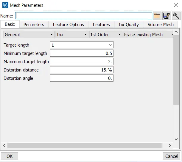
- Click on OK.
- Now click on length under the perimeter section in the mesh deck.
- A window popup in that select the perimeters option and select the face.
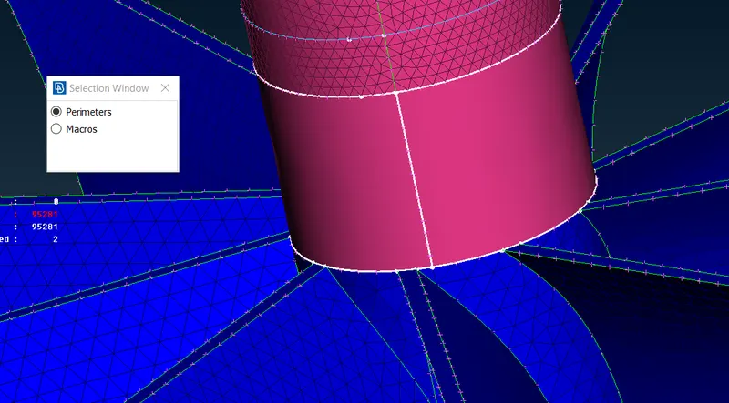
- Do a middle click to confirm the selection and a window will pop up.
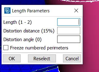
- In that, we can see that the length is (1-2) mentioned we will keep it as it is and close it.
- Now select the macros option and select the face.
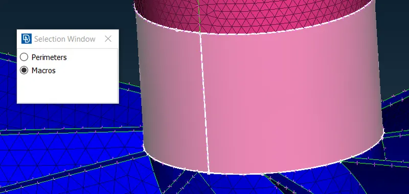
- Do a middle click to confirm the selection and another window will be displayed.
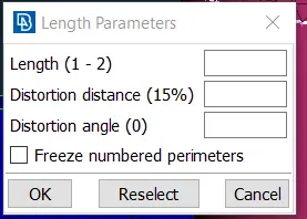
- We can see that the length is (1-2) mentioned we will keep it as it is and close the window.
- Click on spot mesh under the mesh generation section in the Mesh deck.
- Select the face to mesh
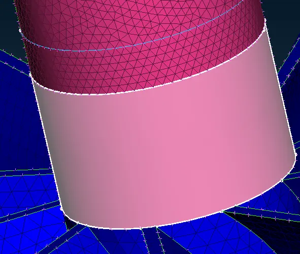
- Do a middle click to confirm the selection and generate the mesh.
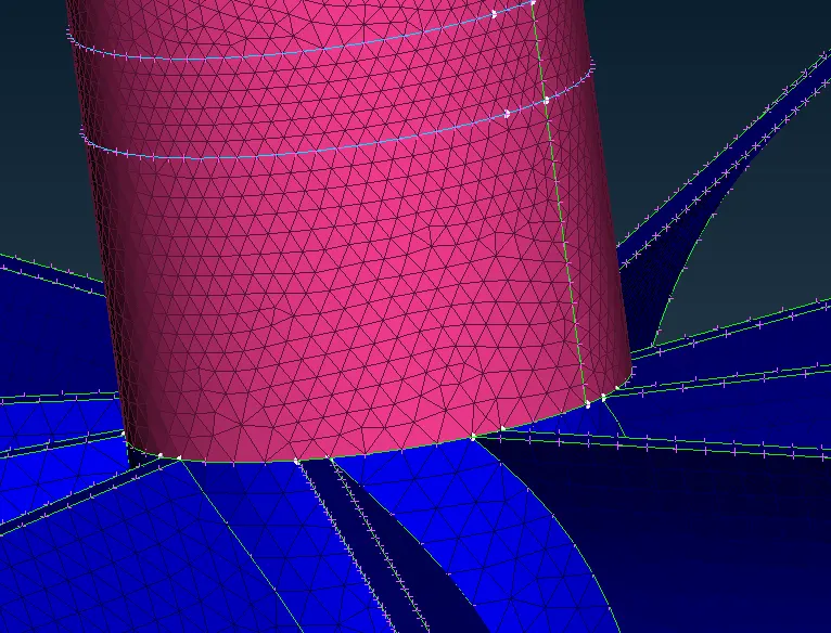
- The mesh is generated successfully and is transitioned from 2 mm to 1mm.
- Make all other entities visible using the ALL option.
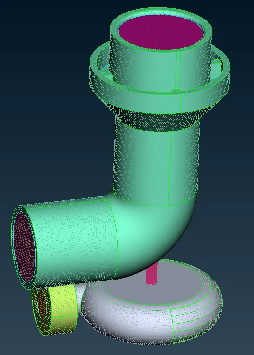
- We can see that the mesh is erased of some faces of the turbo and compressor casing.
- This is due to the same reason as seen above.
- We will try the same method as above and resolve this problem.
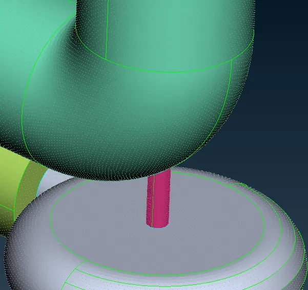
- We have successfully transitioned the mesh.
- But we can still see that there are unmeshed areas.
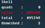
- If we right-click on unmeshed and select the show only option then we can see the unmeshed areas or faces
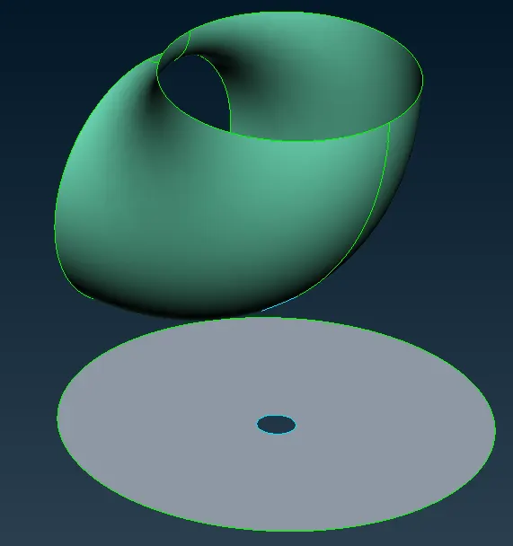
- We will mesh them using spot mesh as we did earlier.
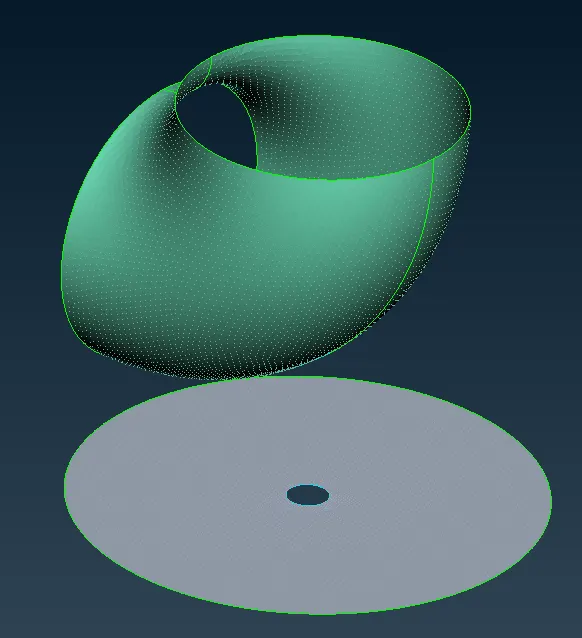
- Now, if we make all entities visible, we can see that the unmeshed areas are zero.
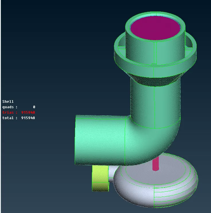
- At the mesh transitioning region, we can isolate that area to have better mesh transition.
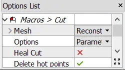
- Click on the cut option under the macros section in the Mesh deck.
- In the options list, select reconstruct mesh and parametric cut.
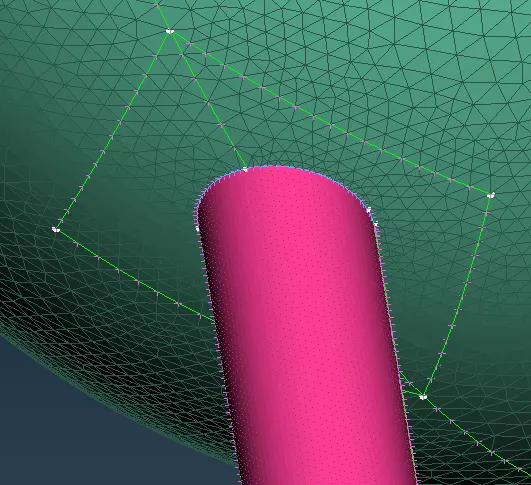
- Now we can cut the surface by selecting any two nodes to create a con.
- We can create the cut at a random location and use whatever shape we want.
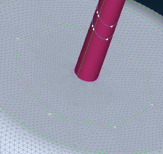
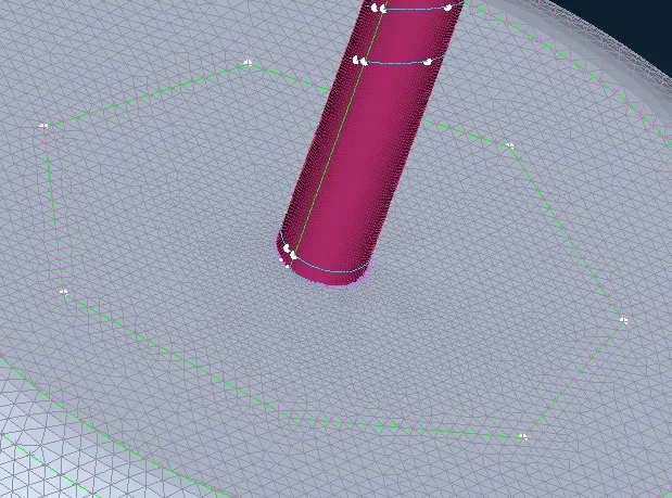
- The mesh in that area is more refined now.
- We will do the same for other surfaces.
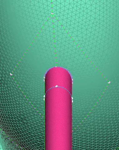
- The above image is the inner surface of the compressor casing.
- The above image is the surface of the turbo casing.
- The above image is the inner surface of the Turbo casing.
- make all the entities visible by clicking on the ALL option.
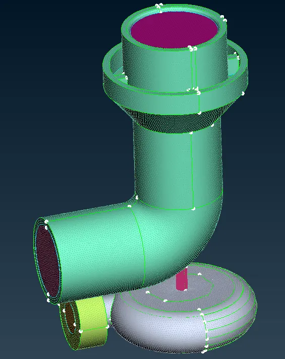
- We have successfully completed the 2D meshing of the Turbocharger.
- Now we will move forward to the volumetric meshing.
Step 6 - volumetric meshing.
- To perform volumetric meshing, we will switch to a volume Mesh deck.
- we first have to define the volume for volumetric meshing.
- To do so long press on the define option which is under the volumes section in the Volume mesh deck and select the auto-detect option.
- A window pops up, in that choose work from the whole db.
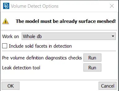
- Click on OK.
- The software auto-detect the volumes.
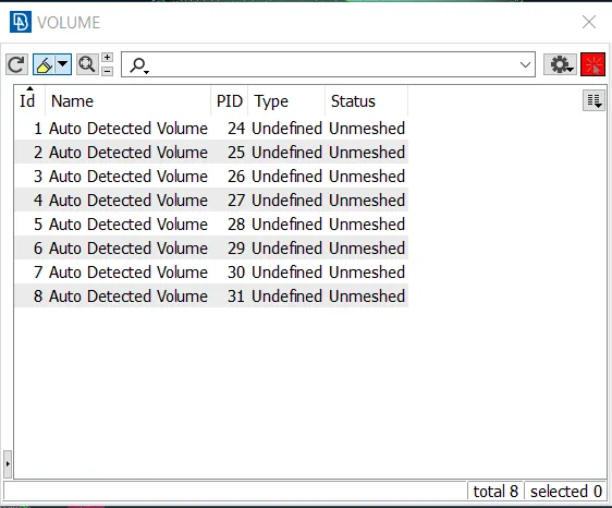
- Now we won't need all these volumes. we will delete the volumes which have a thickness or through which the fluid is not going to flow.
- We have to keep only those volumes through which fluid is going to flow.
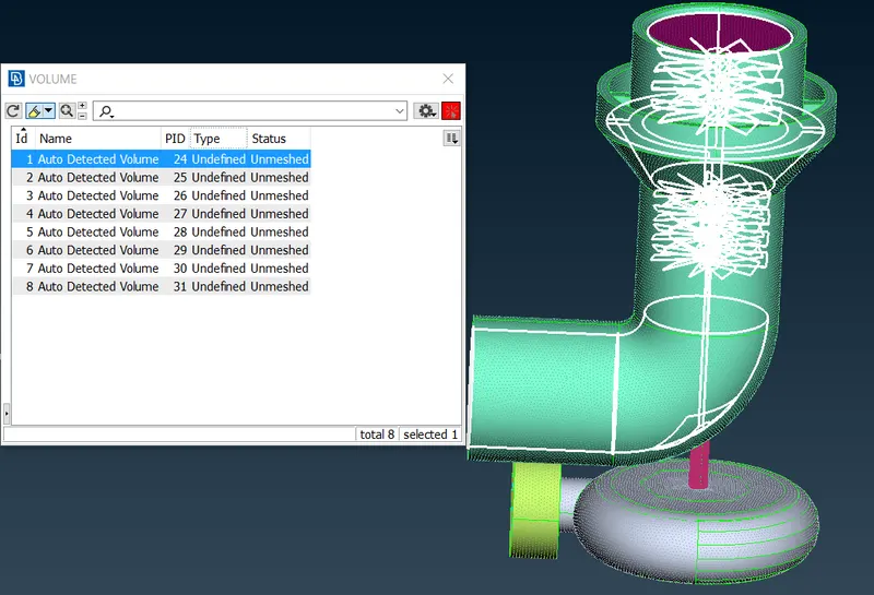
- By clicking on the volume, it highlights the selected volume in the geometry.
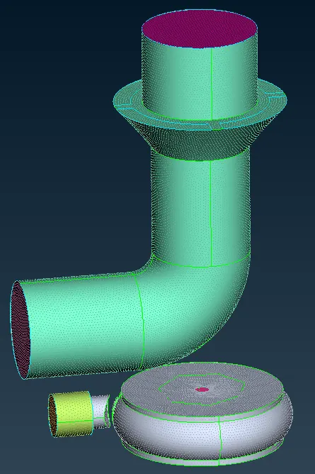
- The first volume is the inner volume of the compressor through which the fluid is going to flow or will be present so we will be needing this volume and we won't delete it.
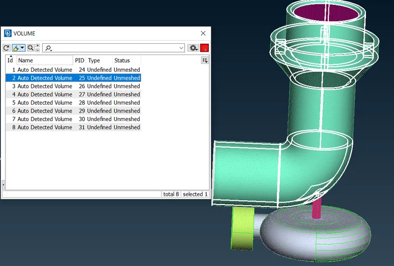
- The second volume had a thickness and there won't be any fluid present in it so we will delete this volume.
- To delete the volume right click on the volume and click on delete
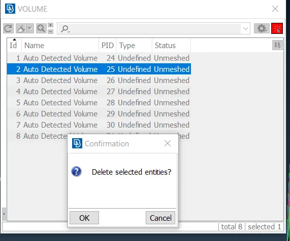
- It asks to confirm, so click on OK.
- Now that volume is deleted.
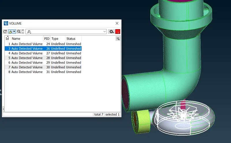
- Moving forward to the third volume, since it is the inner volume of the turbo casing, fluid will be present in it, so we won't delete it.
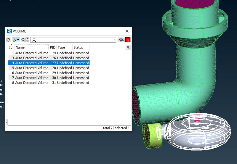
- The fourth volume has a thickness and there won't is any fluid present in it so we will delete it.
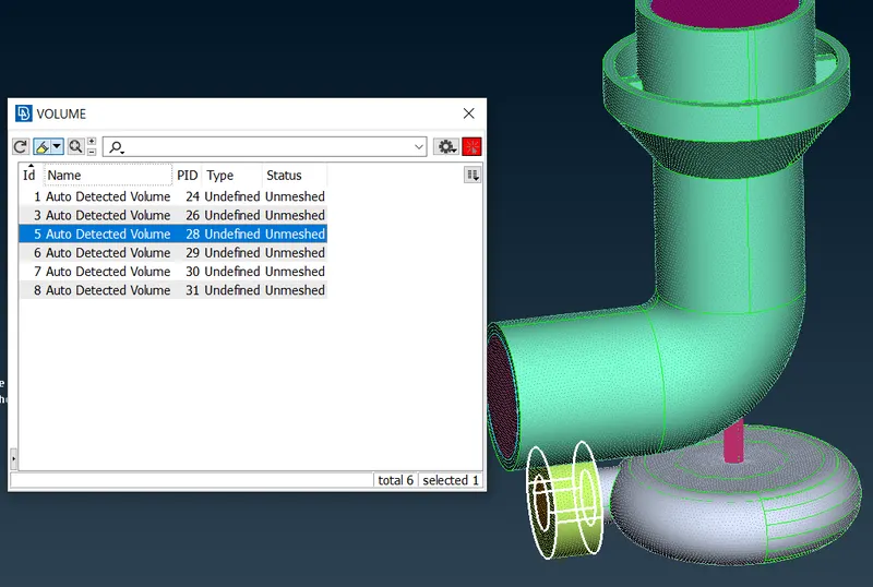
- Even the fifth volume has a thickness and won't have any fluid movement so we will also delete it.
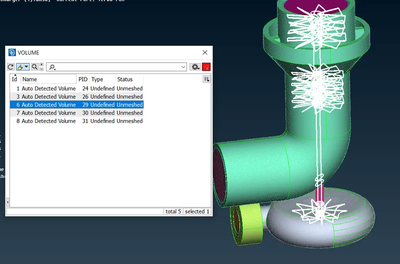
- The sixth volume has the same case, so we will delete it as well.
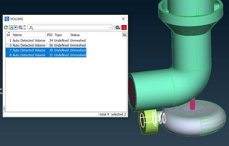
- Fluids will flow through volumes seven and eight so we will keep them.
- Select all these volumes, right-click on them and click on the show only to display only these volumes.
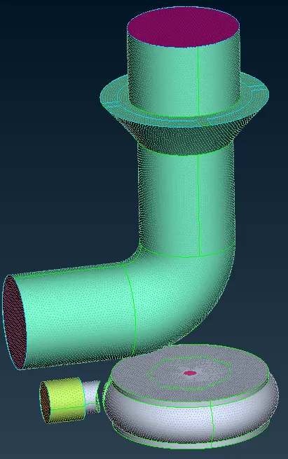
- Now we will perform volumetric meshing on these volumes.
- since volumetric meshing is an intensive task it takes more time, so we will mesh each volume individually instead of doing it in one go.
- To do volumetric meshing right click on the volume and click on Remesh.
- A window pops up, in that selects mesh type as tetra CFD.
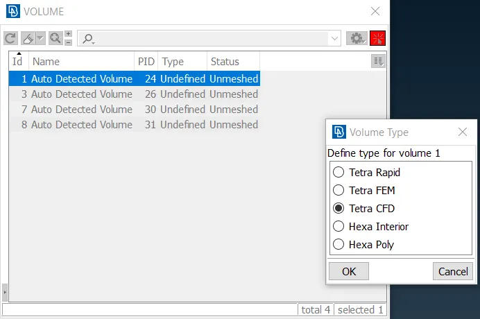
- Click on Ok to start the meshing.
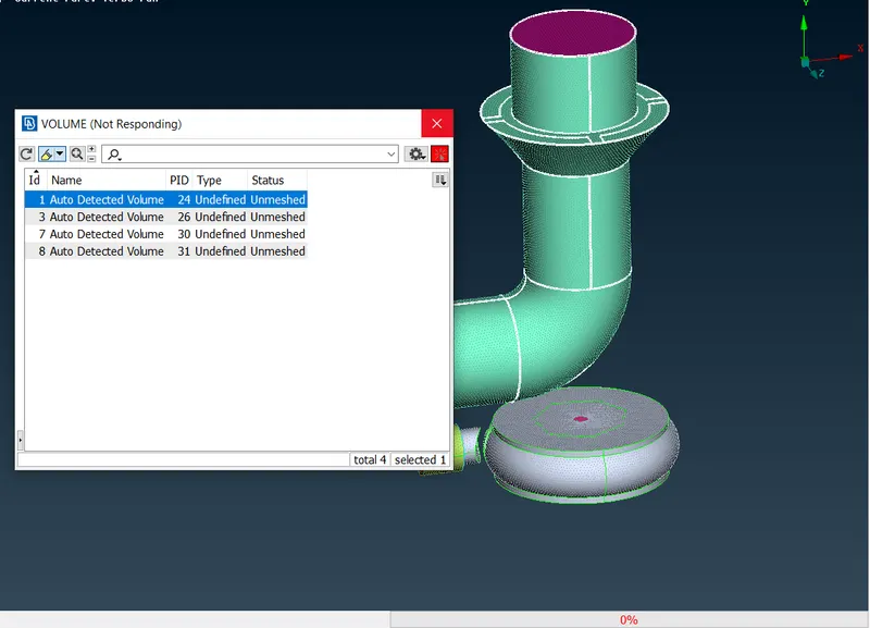
- It will take some time and we can monitor the progress in the progress bar
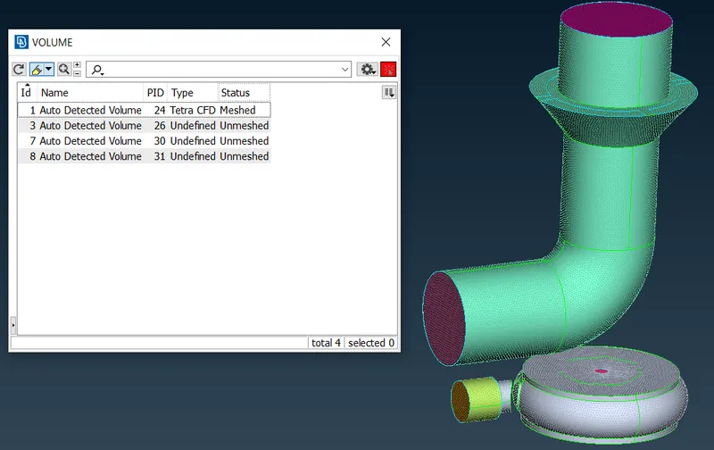
- After meshing the status of the volume changed from unmeshed to meshed and the type is changed from undefined to Tetra CFD.
- Now we will do the same for all other volumes.
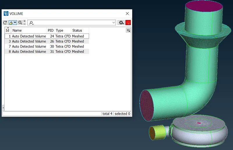
- We have successfully completed the volumetric meshing of the Turbocharger.
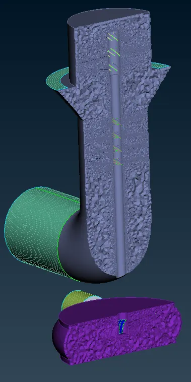
- We can also view the cross-section of the geometry using the not option, in order to view the tetra elements.
Learning Outcome: -
- practiced checking for errors in geometry using geometry checks and solving these errors.
- practiced creating new surfaces using the Existing surface option, fitted option, coons' option, and also using the Fill Hole command.
- got to know about finding single cons by disabling triple cons, double cons, and crosshatches.
- Learned about switching to wireframe mode, PID mode, ENT mode, and PID region mode, and using these for smooth operations.
- learned and practiced making geometry watertight.
- Learned about assigning and renaming the PIDs in PID manager
- learned about deleting the surfaces and overlapping surfaces.
- learned to make cons finer, and project the cons.
- Learned and practiced the use of the Topo option
- learned to make mesh transition from two different lengths effectively.
- learned to isolate the mesh to make it better.
- learned and practiced volumetric meshing, defining volumes, and deleting volumes.
- learned to use the not command to view the cross-section of the volumetric mesh.
- learned the use of viewing options such as geometry, FE-mode, and Volume.
Result: -
- After the successful 2D surface meshing of the turbocharger with Tria elements, we get 916336 elements.
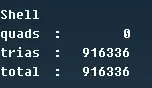
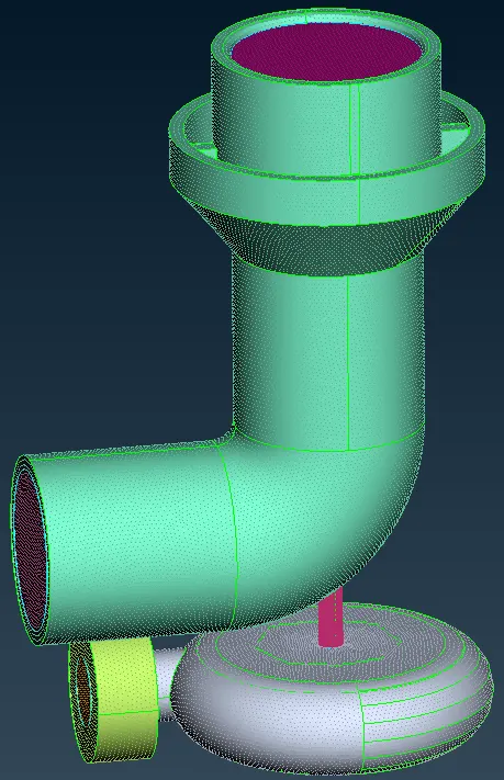
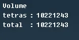
- After the successful Volumetric meshing of the Turbo Charger with Tetra elements, we get 10221243 elements.
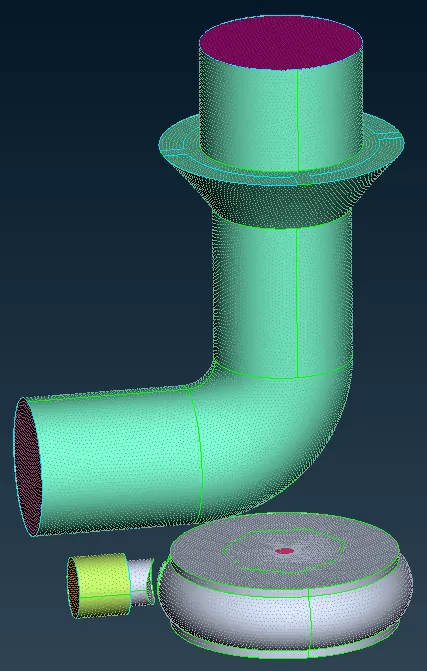
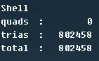
- In the volumetric meshing process, some volumes are deleted so the number of Tria elements from surface meshing is reduced to 802458 elements.
Conclusion: -
- Geometry has to be cleaned perfectly in order to have good meshing results.
- different mesh lengths are used for different components in order to capture the geometry efficiently and without any errors.
- The contact region of different mesh lengths gives errors that have to be solved by giving mesh ranges.
- After successful 2d surface meshing, volumetric meshing can be performed.
- volumes have to be defined for volumetric meshing
- the thickness volumes had to be deleted for volumetric meshing.
- The number of Tria elements of 2d surface mesh is reduced after volumetric meshing because the thickness volumes are deleted.
- CFD meshing is executed successfully.
https://drive.google.com/file/d/1pX31koc6vpeCxuTa1c32sVd5g6n5iHam/view?usp=sharing