Week 2 Challenge : Surface meshing on a Pressure valve
Aim / Objective: - Perform 2D meshing on the surface of a pressure valve for three separate cases by maintaining the target lengths of 1 mm, 3 mm, and 5 mm.
Procedure: -
Step 1 - To Import CAD file in ANSA
- For importing the CAD Geometry go to file and click open.
- go to the directory where the cad file is present.
- select the geometry file with the .ansa extension and click open.
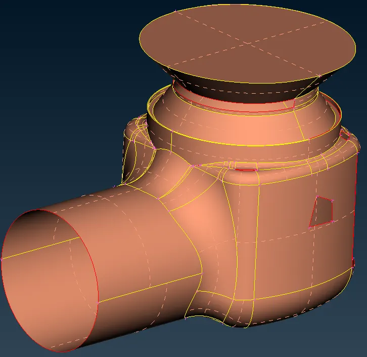
- After importing the geometry switch the Draw mode to PID.
- Also, enable cross Hatches and labels.
Step 2 - Geometrical Quality Check
- There may be errors, single cons, holes, missing surfaces, and so on in a geometry.
- Before meshing up we have to fix these errors to obtain a good mesh and a water-tight geometry.
- To perform checks, go to the checks option in the upper toolbar and select geometry in that.
- A window pops up, selects all the checks but exclude unmeshed macros because we haven't meshed the geometry yet.
- also don't select the sharp edges to check.
- After selecting the required checks click on execute.
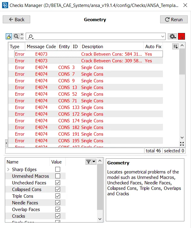
- It displays all the errors present in the geometry.
- most of these errors are Single cons and cracks.
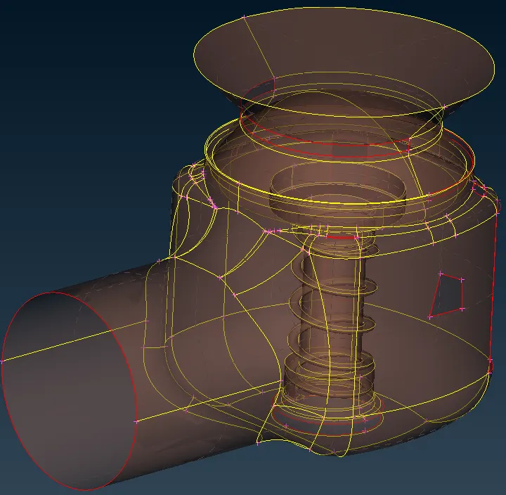
- Single cons are Cons that are shared by only one surface.
- They are represented by the red line.
- Single cons and cracks also represent that the geometry is open.
- so, we need to patch this up to create a water-tight geometry.
Step 3 - Topological cleanup
- First, we have to fix all the single cons and close the geometry.
- For patching the surfaces, we will be dealing with the Faces and Surfaces sections.
- To create a new surface, click on the new option in the Faces section under the Topo deck.
- A window pops out in which we have different algorithms to create a surface.
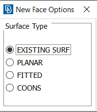
- The algorithms are Existing surface, Planar, Fitted, and Coons.
- The existing Surface option is used when we want the surface on an existing surface.
- The planar option is used when the surface is in a flat plane.
- The fitted option is used when the surface is non-planar
- The Coons option is the best option to create a surface, it perfectly captures the geometry and creates the surface.
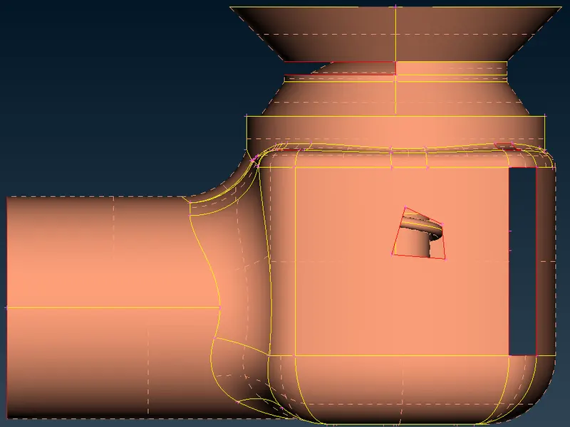
- Patch this surface with the existing surface option
- Select cons using the Loop methods
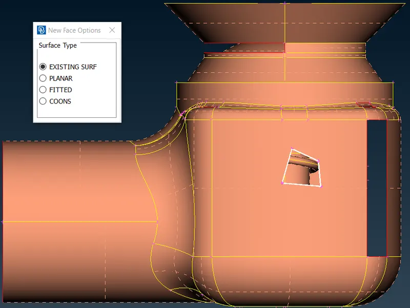
- In the loop method, all the single cons which are connected are selected with a single click.
- do a middle click to confirm the selection.
- now select the surface by clicking on the cross hatch of that surface

- The new surface is created and the single cons are turned into double cons which are represented by a yellow line.
- Now there is a rectangular hole, to patch this we will use the fitted option.
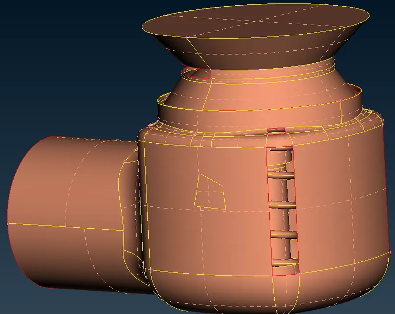
- select the fitted option in the window and using the loop method select the single cons.
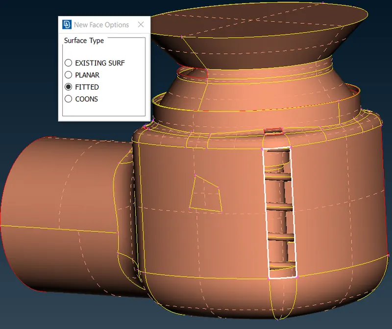
- Do a middle click to confirm the selection.
- a window will pop up in which it will ask to confirm the surface or we can choose an alternate surface.
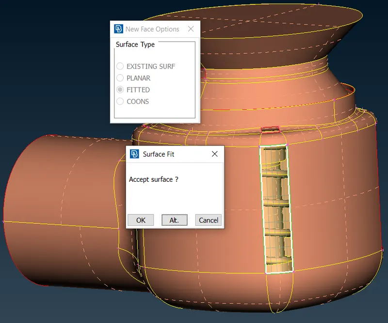
- Click on OK to generate the surface.
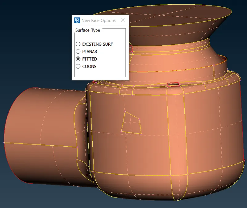
- On the other side of geometry, we can see that other single cons keep geometry open.
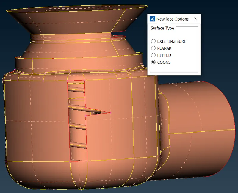
- To patch this, we will use the Coons option
- In the window now select the coons option
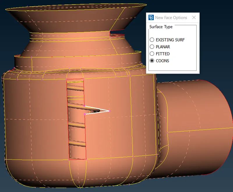
- using the Ent method, select only these two single cons and do a middle click to confirm the selection.
- a window will pop up in which it will ask to confirm the surface or we can choose an alternate surface.
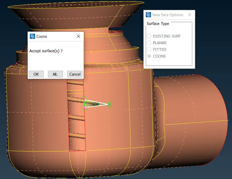
- Click on OK to generate the surface.
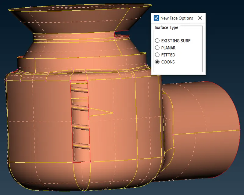
- Now using the loop method select the remaining rectangle and patch it up.
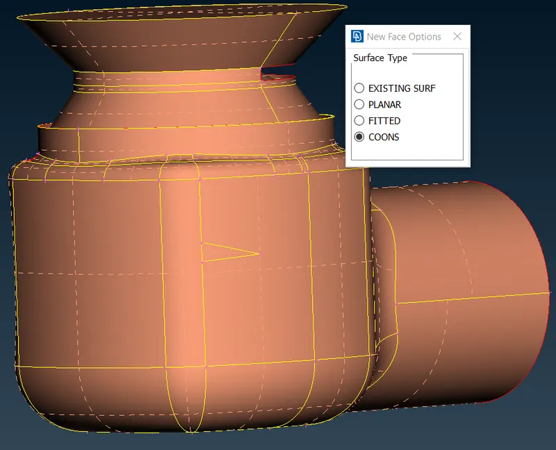
- We did this process separately because selecting all the single cons, in this case, doesn't generate the desired surface.
- Also, the length of two single cons should be approximately the same to generate a good surface.
- we can see there are some cracks in this geometry
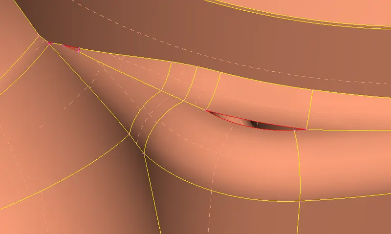
- We can also patch these cracks up using fill hole options
- Click on the Fill hole option in the cons section under Topo Deck
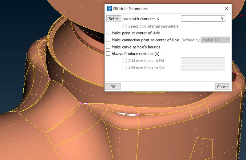
- we can select multiple holes at once and click on okay or do a middle click to generate a surface there.
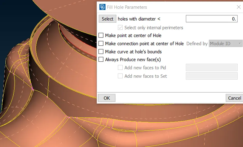
- The remaining single cons can be fixed with the coons option.
- there are still some single cons at the bottom.
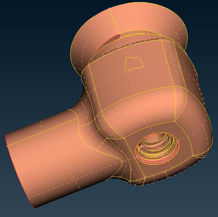
- As these two single cons are circular and near to each other, the surface generated is not as desired.
- So, we have to use the ENT method to generate a surface here i.e. to solve the error part by part.
- If it is difficult to see the single cons we can turn off triple cons, double cons, and crosshatches and switch to wireframe mode by pressing CTRL + Shift or by deactivating shadow mode.
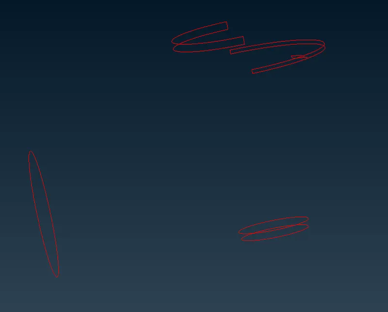
- using Coons option and ENT mode select the cons with approximately the same lengths
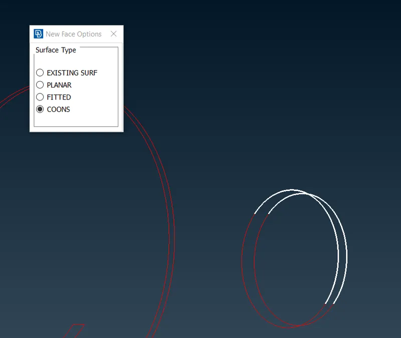
- and generate the surface.

- and repeat the same for the remaining cons using the loop method.
- There are some single cons present at the neck of the valve.
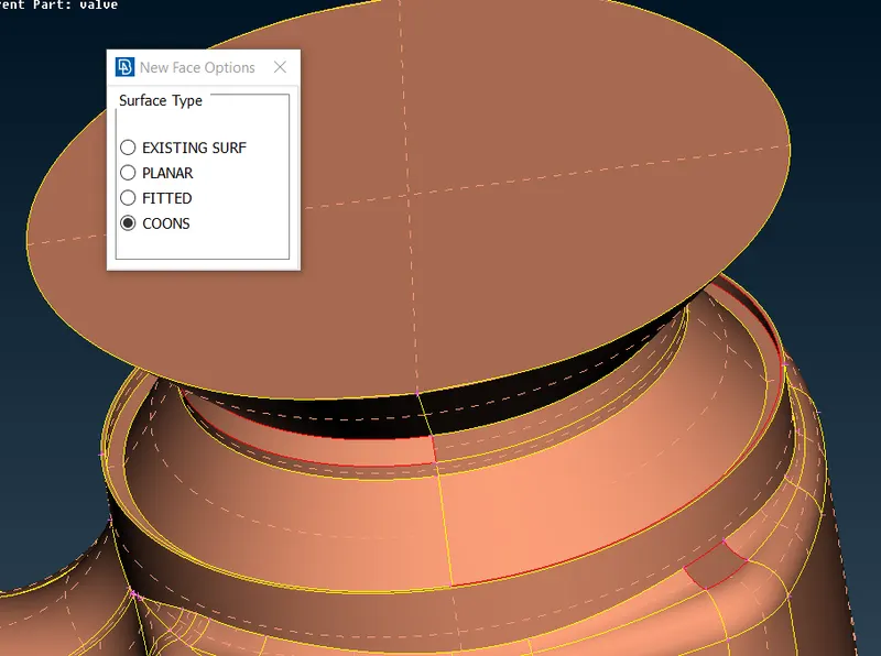
- we can similarly fix these using coons option.
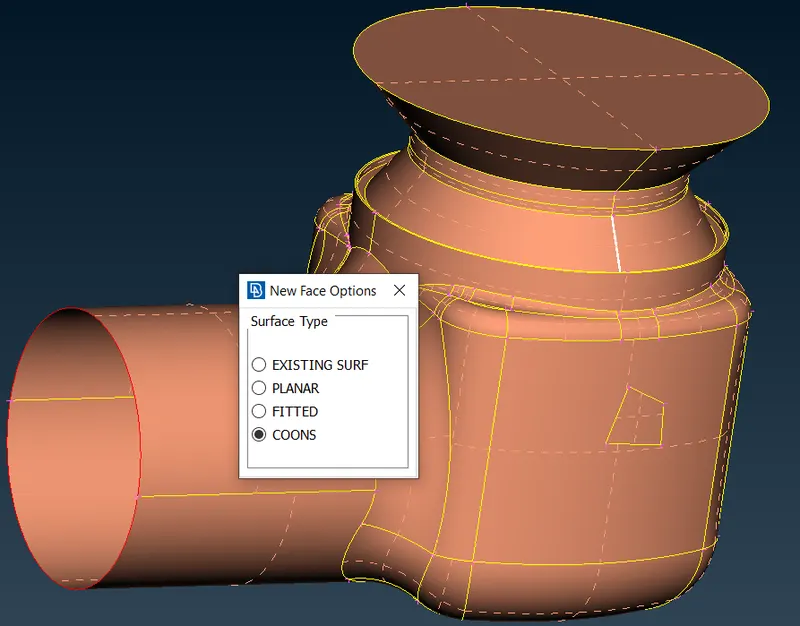
- now if we switch to wireframe mode, we can see that we have one single con which we can fix using the coons option and loop method directly since we have to seal the geometry.
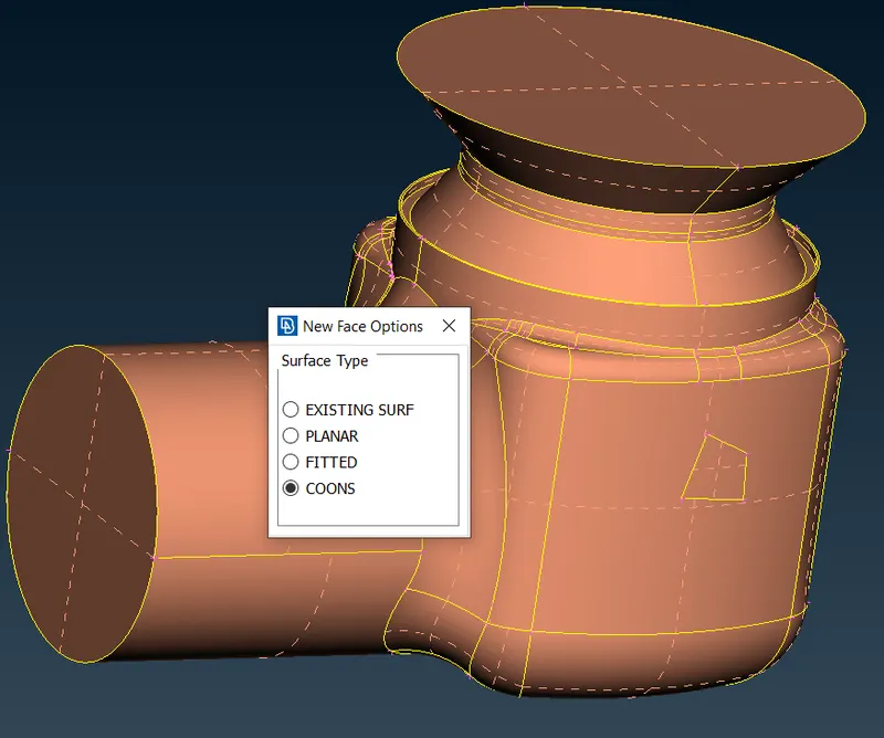
- Now if we run the geometry check it doesn't display any errors.
- but if we look at the bottom, we have a hole that we have to patch because we want the geometry to be watertight.
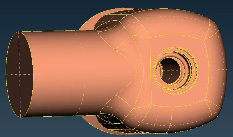
- using coons option, we can generate a surface over there.
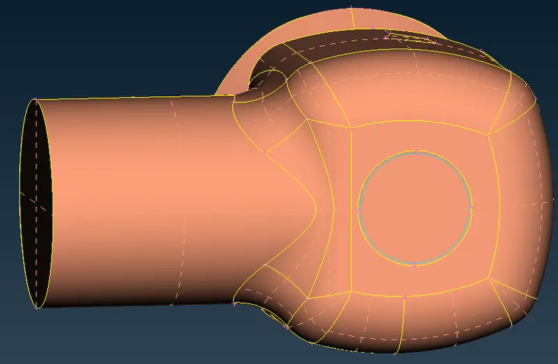
- Now we see that a triple con is created over there which is represented by cyan color.
- Triple cons are created when the same cons/edge is shared by three surfaces
- And if we run the geometry check, it displays the triple cons as an error
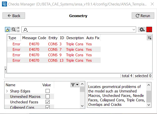
- But it is just a warning to let us know that a triple cons is present in geometry.
- Double cons are expected in geometry and are not considered errors.
- Now before we move forward, we have to eliminate/delete the cons which are very close together or which are unwanted.
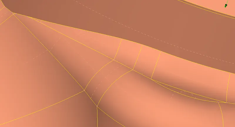
- we delete these cons because while meshing if the space between these cons is less than the target length then it won't generate the appropriate mesh.
- We can also measure the distance between the cons using the measure tool.
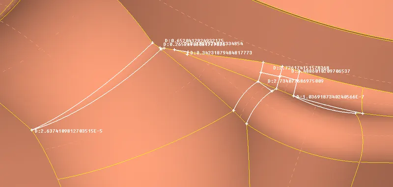
- so, we will need the space between the cons to be greater than the mesh length.
- To delete the cons we will use the cut option.
- Click on the cut option in the Faces section under the Topo Deck.
- Now right click on the cons which are nearer to each other or are unwanted.
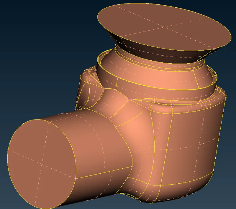
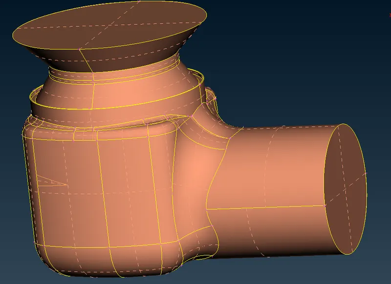
Step 4 - Assign PID (Property Id)
- Whenever we are using ANSA make sure we are in PID mode.
- whatever elements/surfaces we see are in the PID mode.
- We have to assign PID to each component in the model
- There is an option PID manager in the top toolbar
- To create a new PID open the PID manager.
- right-click in the window and click on new and select PSHELL in that again select PSHELL.
- a window pops out in that type the name of the component
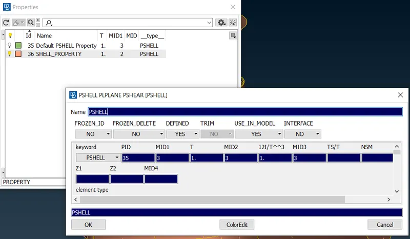
- now create the PID for Inlet, Outlet, Body, Base surface, Spring, Valve head, column.
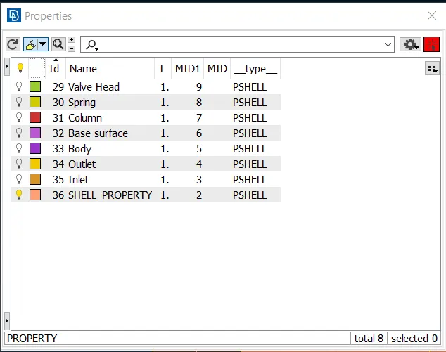
- We can also change the color of PID by double-clicking on the color box and selecting the required color.
- To apply the Inlet PID to the element right-click on the PID and choose apply
- Now select the inlet surface by clicking on the cross hatch and do a middle click to confirm it.
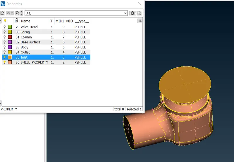
- The same can be done for Outlet PID.
- To assign the Body PID, make the inlet and outlet PID invisible by clicking on the bulb
- now change the selection method to the PID region and click on the outer casing.
- It selects the body and won't select the components inside the body.
- Do a middle click to confirm the selection.
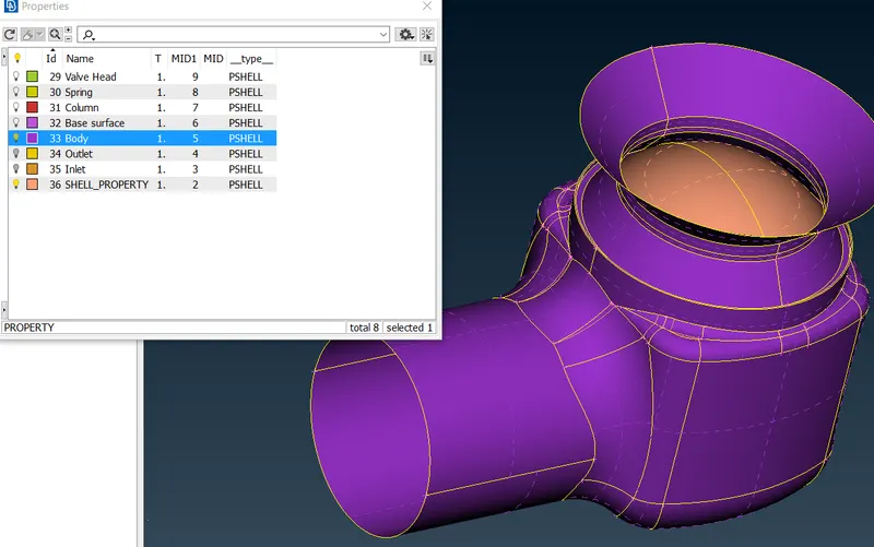
- Assign the Base surface PID to the base surface in the same way.
- Hide the Body and Base Surface.
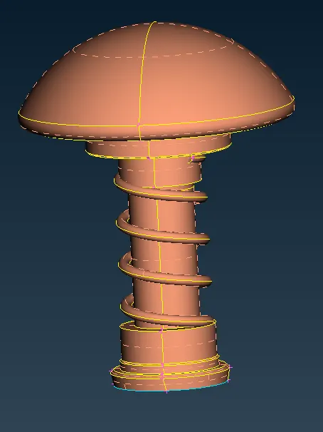
- Now assign the Spring PID to Spring using the PID region selection method.
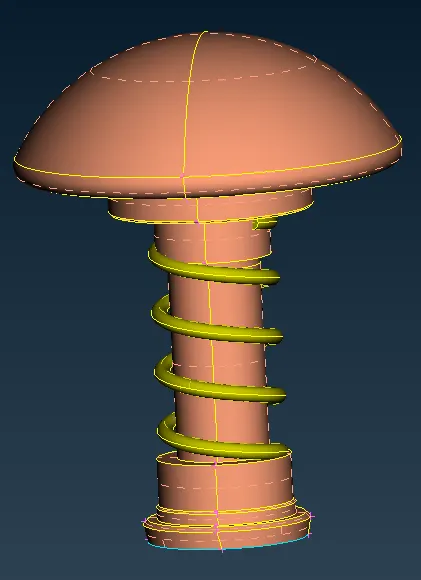
- hide the Spring PID and Lock the View.
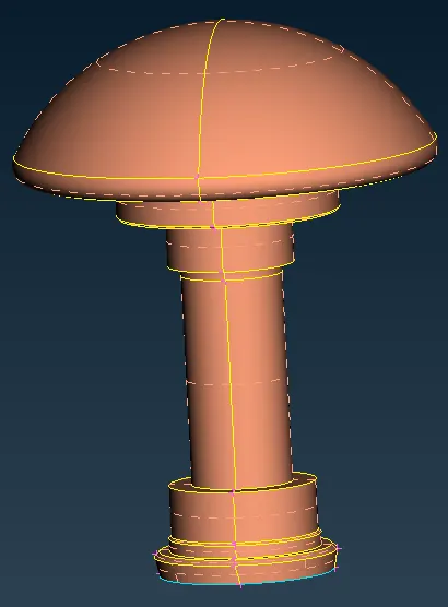
- To assign the Valve Head PID we can select the valve head using the ENT method
- But it is difficult to do that using the ENT method so we will use the PID region selection method.
- For that, we first have to disconnect the Valve head from the column by using the NOT Boolean option
- using the NOT tool to hide this small surface that connects the valve head to the column.
- now assign the Valve head PID to the valve head.
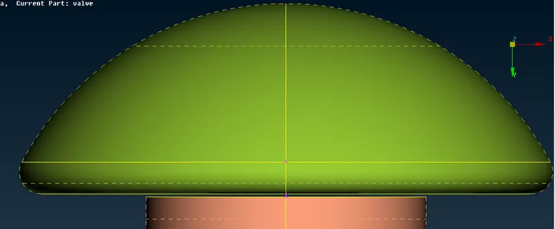
- Click on All to bring back all the entities in the Lock mode.
- Hide the Valve head and assign the Column PID to the remaining entities.
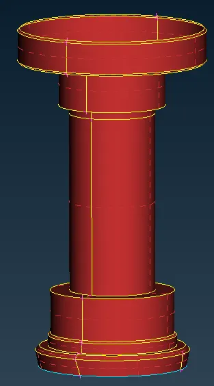
- deactivate Lock mode and make all the entities Visible.
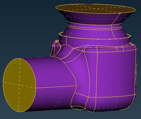
- now we have successfully assigned the PID to respective entities.
Step 5 - Initiate Meshing
Case 1 - Meshing with 1mm target Length.
- Switch to Mesh deck from Topo Deck
- Click on the Mesh Parameter option in the top toolbar
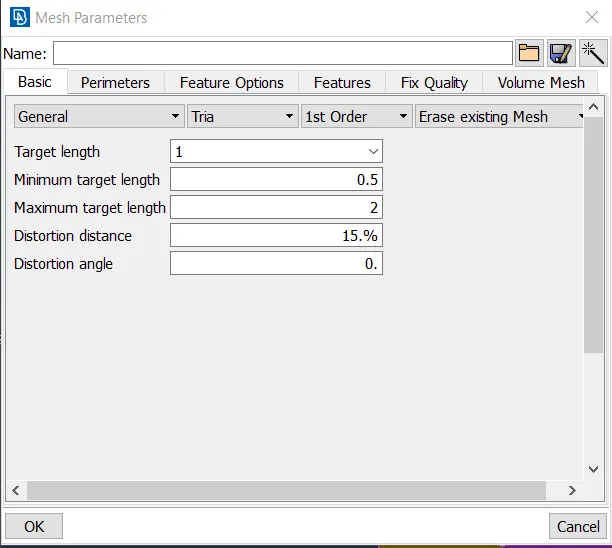
- A window pops up, select general mesh, Tria element of 1st order.
- set target length as 1mm, minimum target length as 0.5mm, maximum target length as 2mm and click on OK.
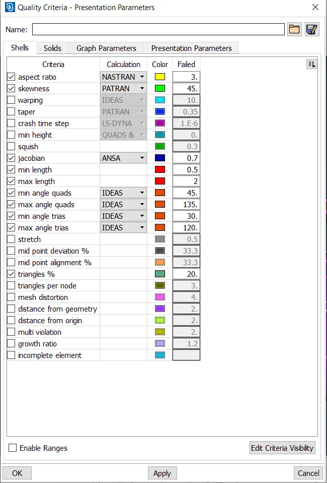
- Click on Quality criteria and enable aspect ratio, skewness, Jacobian, min length, max length, min angle quad, max angle quad, min angle Tria, max angle Tria, triangles %.
- set the min length as 0.5 and max length as 2, and click on OK.
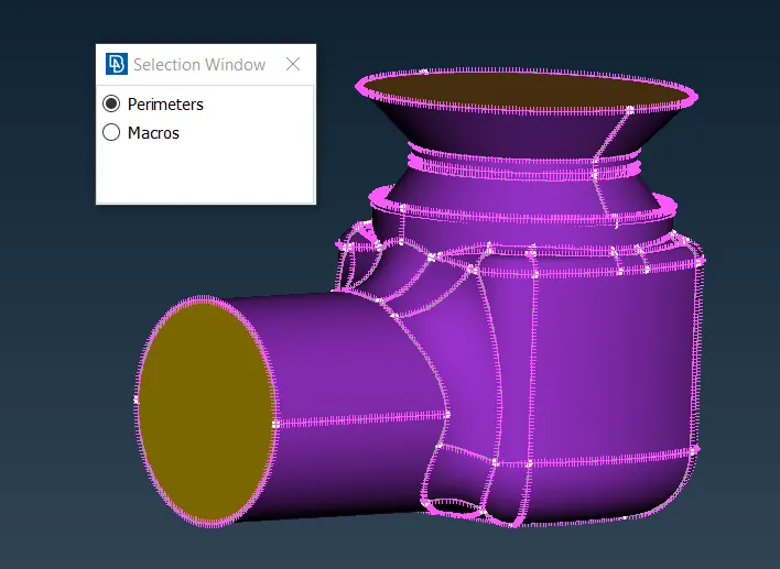
- click on length in perimeter section under mesh deck.
- a window pops up, select the perimeter option, and using the box select the entire geometry, do a middle click to confirm the selection.
- another window pops up in that enter the length as 1 and click OK.
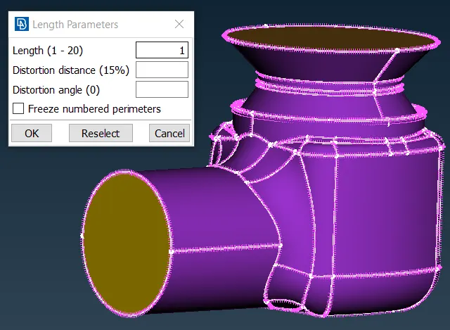
- Now select the macros option and select the geometry using box selection, do a middle click to confirm the selection.
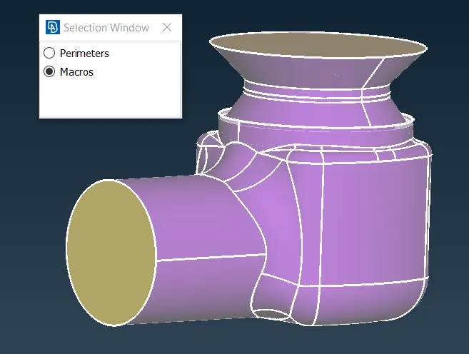
- in the window enter the length as 1 and click okay
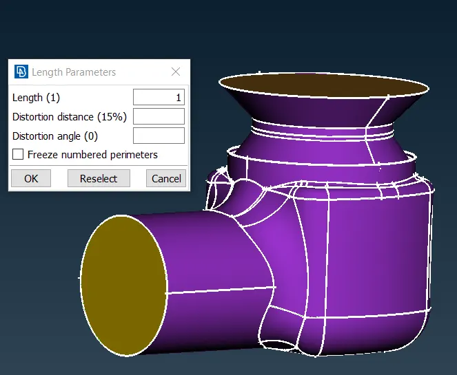
- now select the spot mesh option in the mesh generation section under the mesh deck.
- select and hold the spot mesh option to see the drop-down option.
- From the drop-down options select the visible option.
- By selecting visible we don't have to manually select the surfaces to mesh instead this option will mesh everything visible on the screen.
- The mesh is completed.
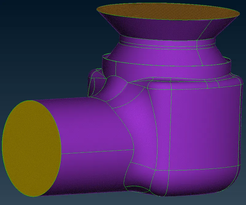
- We can cross-check the mesh length using the measure tool.
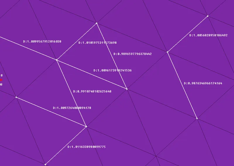
- by using the measure tool, we find that the element length is approximately equal to 1mm.
Case 2 - Meshing with 3mm target length
- Switch to Mesh deck from Topo Deck
- Click on the Mesh Parameter option in the top toolbar
- A window pops up, select general mesh, Tria element of 1st order.
- set target length as 3mm, minimum target length as 2.5mm, maximum target length as 3.5mm and click on OK.

- Click on Quality criteria and enable aspect ratio, skewness, Jacobian, min length, max length, min angle quad, max angle quad, min angle Tria, max angle Tria, triangles %.
- set the min length as 2.5 and max length as 3.5, and click on OK.
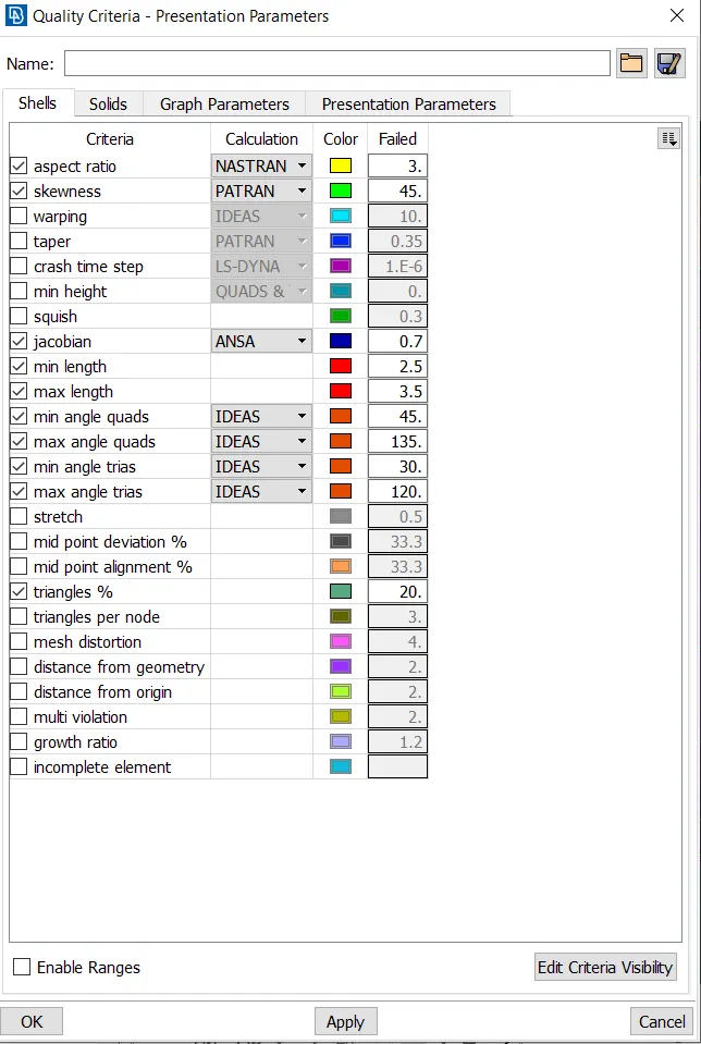
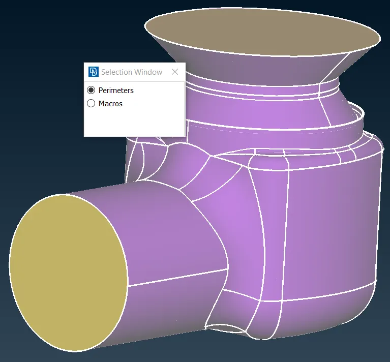
- click on length in perimeter section under mesh deck.
- a window pops up, select the perimeter option, and using the box select the entire geometry, do a middle click to confirm the selection.
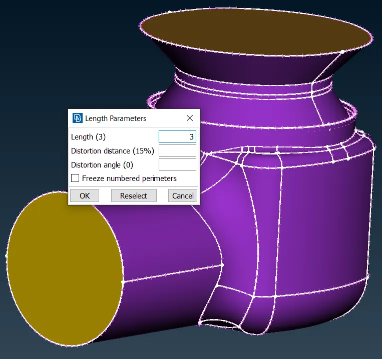
- Another window pops up in that enter the length as 3 and click OK
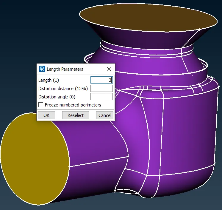
- Now select the macros option and select the geometry using box selection, do a middle click to confirm the selection.
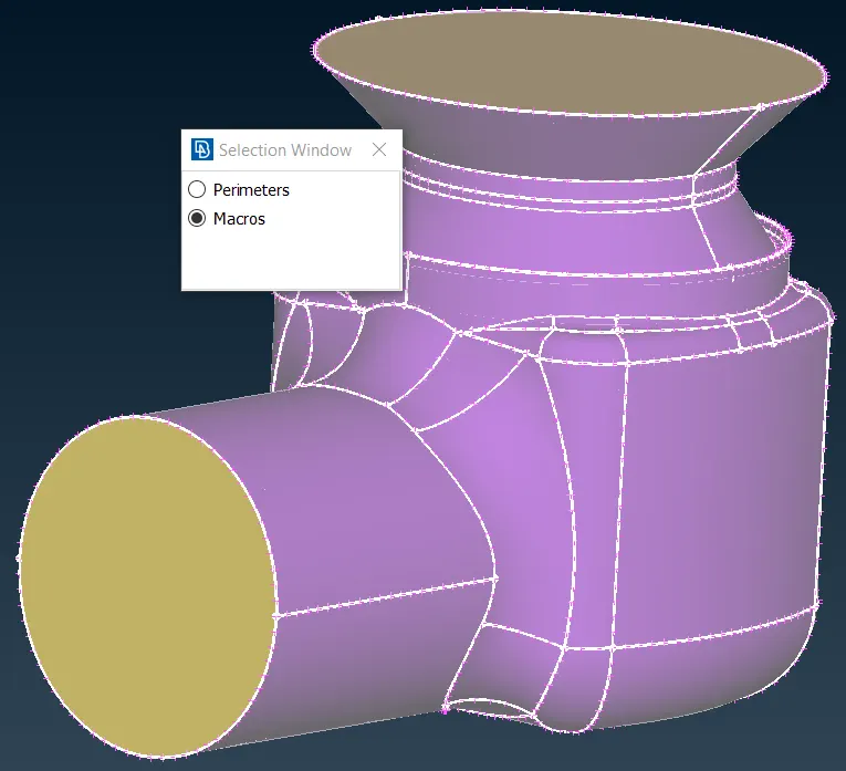
- in the window enter the length as 3 and click okay
- now select the spot mesh option in the mesh generation section under the mesh deck.
- select and hold the spot mesh option to see the drop-down option.
- From the drop-down options select the visible option.
- By selecting visible we don't have to manually select the surfaces to mesh instead this option will mesh everything visible on the screen.
- The mesh is completed.
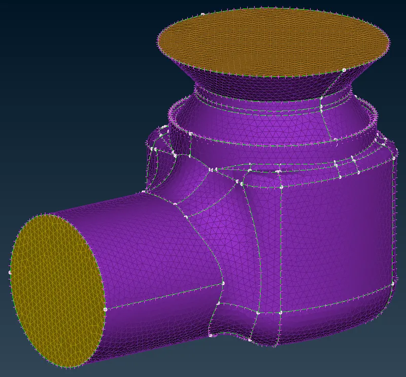
- We can cross-check the mesh length using the measure tool.
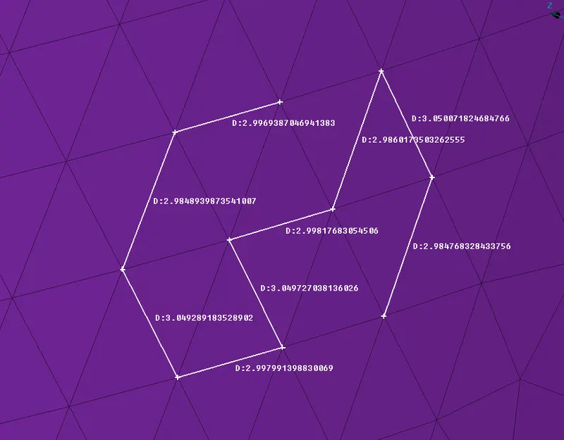
- by using the measure tool, we find that the element length is approximately equal to 3mm.
Case 3 - Meshing with 5mm target length
- Switch to Mesh deck from Topo Deck
- Click on the Mesh Parameter option in the top toolbar
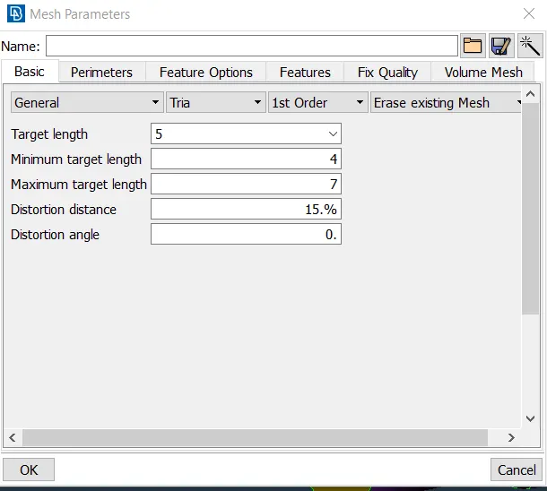
- A window pops up, select general mesh, Tria element of 1st order.
- set target length as 5mm, minimum target length as 4mm, maximum target length as 7mm and click on OK.
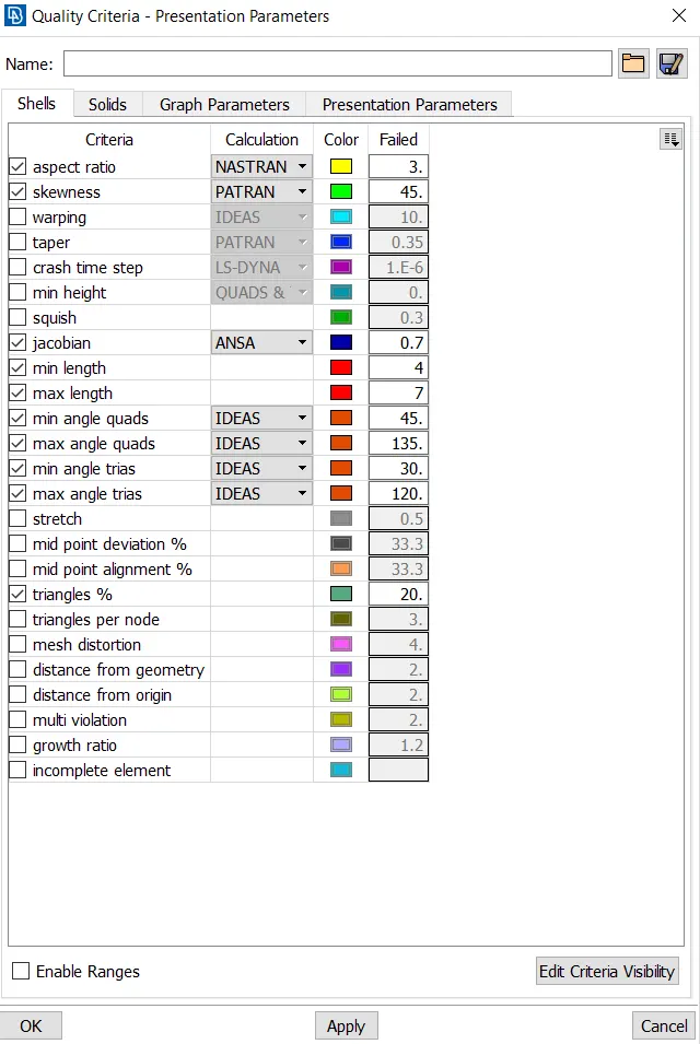
- Click on Quality criteria and enable aspect ratio, skewness, Jacobian, min length, max length, min angle quad, max angle quad, min angle Tria, max angle Tria, triangles %.
- set the min length as 4 and max length as 7, and click on OK.
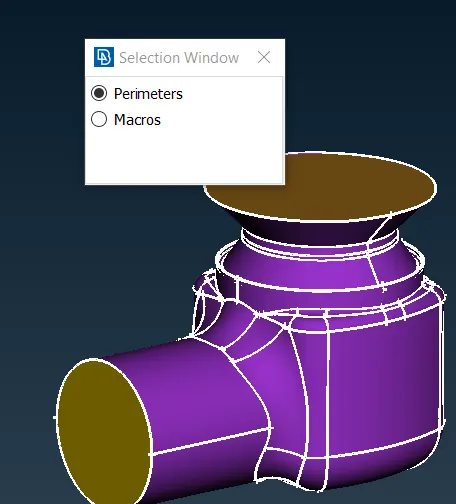
- click on length in perimeter section under mesh deck.
- a window pops up, select the perimeter option, and using the box select the entire geometry, do a middle click to confirm the selection.
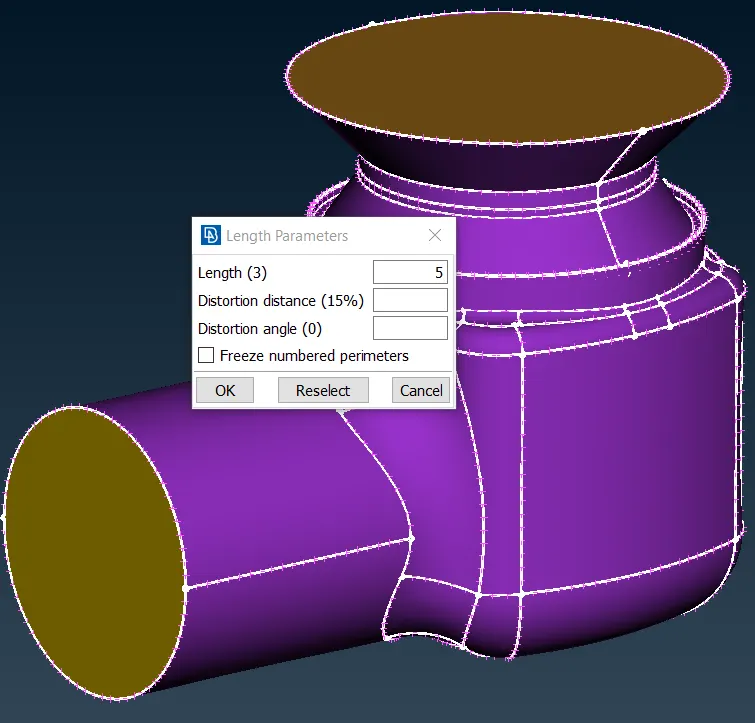
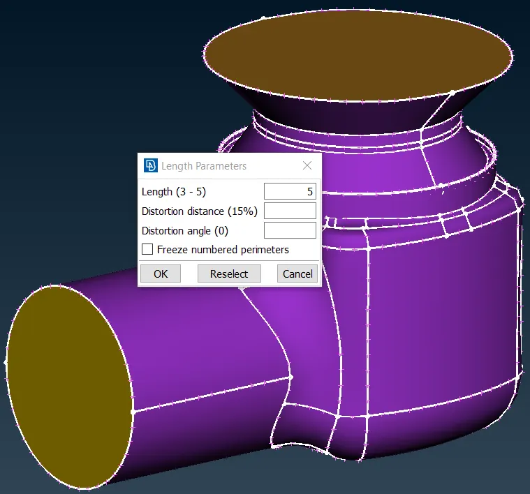
- Another window pops up in that enter the length as 5 and click OK
- Now select the macros option and select the geometry using box selection, do a middle click to confirm the selection.
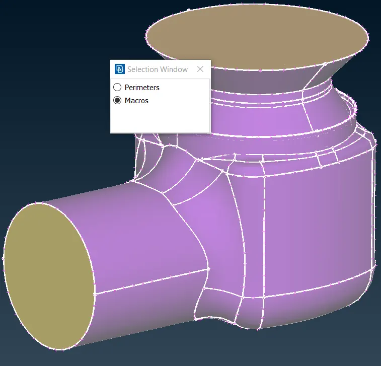
- in the window enter the length as 5 and click okay
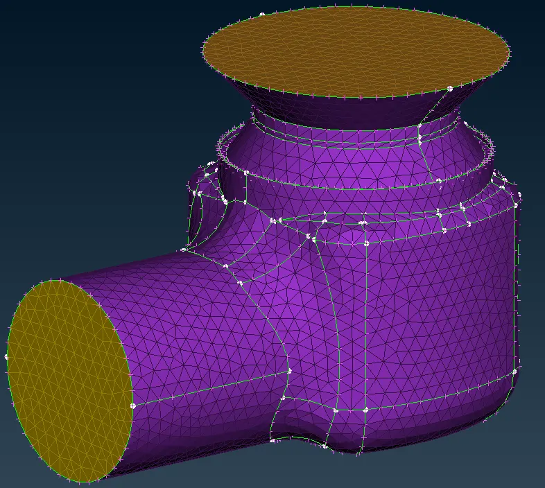
- now select the spot mesh option in the mesh generation section under the mesh deck.
- select and hold the spot mesh option to see the drop-down option.
- From the drop-down options select the visible option.
- By selecting visible we don't have to manually select the surfaces to mesh instead this option will mesh everything visible on the screen.
- The mesh is completed.
- We can cross-check the mesh length using the measure tool.
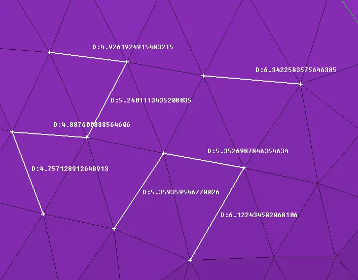
- by using the measure tool, we find that the element length is approximately equal to 5mm.
Learning Outcome: -
- I learned to check for errors in geometry using geometry checks and solve these errors.
- Learned to create new surfaces using the Existing surface option, fitted option, coons option, and also using the Fill Hole command.
- practiced deleting cons and learned the effect of closely packed cons on meshing quality.
- got to know about finding single cons by disabling triple cons, double cons, and crosshatches.
- Learned about switching to wireframe mode, PID mode, ENT mode, and PID region mode, and using these for smooth operations.
- learned and practiced making geometry watertight.
- Learned about the effects of different target lengths and how it affects the meshing quality of the geometry
Result: -
Case 1 - 1mm target length
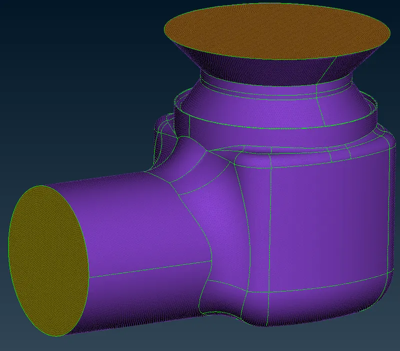
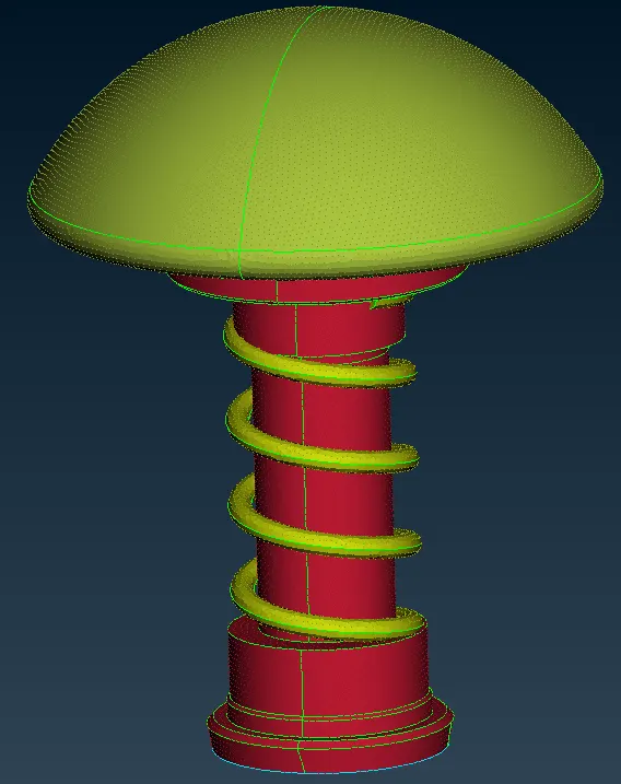
- 1mm mesh successfully captures the geometry without degrading the quality or shape of the surface.
- All the entities Inlet, Outlet, Body, base surface, column, spring, and valve head are meshed perfectly.
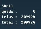
- After successful meshing of the pressure valve with the Target element length of 1mm and element type as Tria, we got 209926 Tria elements.
Case 2 - 3mm target length
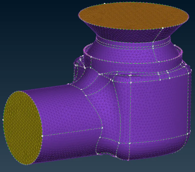
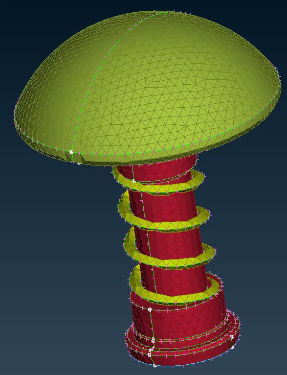
- 3 mm mesh is able to capture large geometry such as the inlet, outlet, body, and base surface.
- It is even able to mesh the column properly but when it comes to small surfaces like the spring and valve head it doesn't perform well.
- It makes the surface quality of the spring decrease it even changes the shape of the spring slightly.
- The valve head is meshed properly but at its edge, the surface quality decreases also some elements are pressed inside which reduces the effectiveness of this mesh.
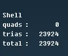
- After successful meshing of the pressure valve with the Target element length of 3mm and element type as Tria, we got 23928 Tria elements.
Case 3 - 5mm target length
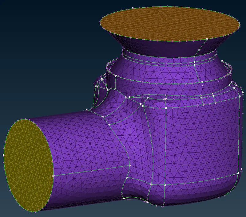
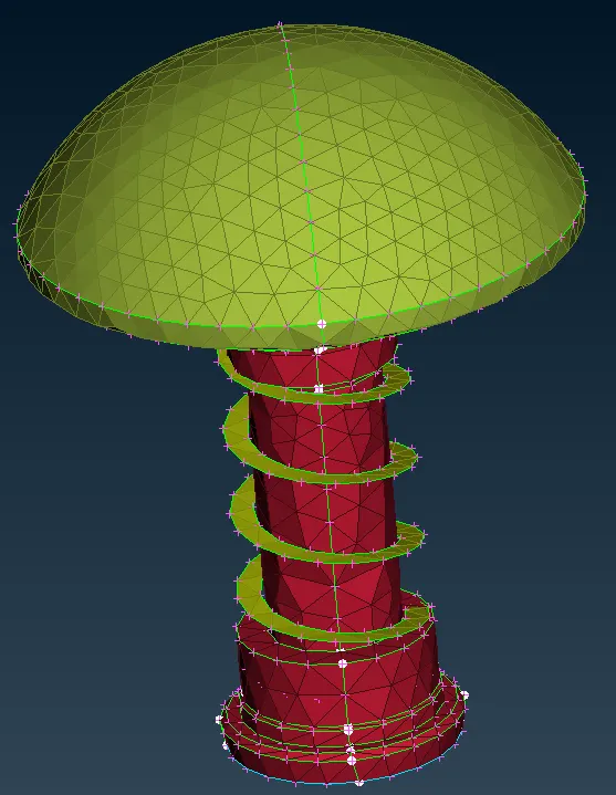
- 5mm mesh size meshes the surface with very large elements and is not able to capture small surfaces.
- large surfaces on the body, inlet, and outlet are captured very well to some extent but the valve head is somewhat distorted.
- Even the spring has lost its shape and we can say the meshing has failed in the spring
- This is due to the element length being smaller than the mesh length.
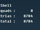
- After successful meshing of the pressure valve with the Target element length of 5mm and element type as Tria, we got 8784 Tria elements.
Conclusion: -
- 1mm target length captures small surfaces very well whereas 3mm and 5mm target lengths degrade the surface quality and shape.
- For meshing the large surfaces 3mm target length is good.
- For meshing very large surfaces 5mm target length will be a good choice.
- For meshing small surfaces 1mm target length is excellent.
- As the target length is increased the number of Tria elements decreases and vice versa.
- Also, as the target length is increased the file size decreases.
- To capture small surfaces efficiently, we should use small Target lengths.