Project 1 : CFD Meshing for Tesla Cyber Truck
Aim / Objective: - To carry out the Topological Clean-up and perform a CFD Meshing for the Tesla Cyber Truck.
Procedure: -
Step 1 - To Import CAD file in ANSA
- For importing the CAD Geometry go to file and click open.
- Go to the directory where the cad file is present.
- select the geometry file with the .ansa extension and click open.
- After importing the geometry enable cross Hatches and labels.
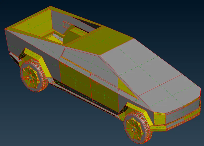
Step 2 - Geometrical Quality Check
- There may be more errors, single cons, holes, missing surfaces, overlapping surfaces, and so on in geometry.
- Before meshing up we have to fix these errors to obtain a good mesh and a water-tight geometry.
- To perform checks, go to the checks option in the upper toolbar and select geometry in that.
- A window pops up, select all the checks but exclude unmeshed macros because we haven't meshed the geometry yet.
- Also don't select the sharp edges to check.
- After selecting the required checks click on execute.
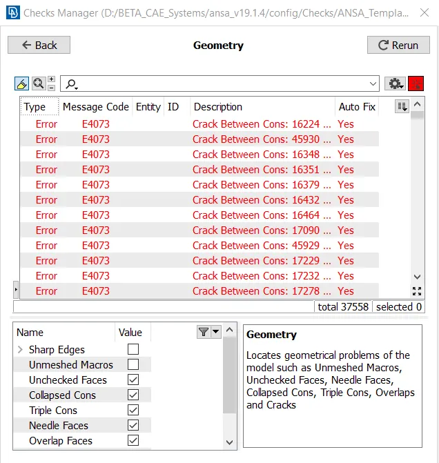
- We can see that the model has many errors such as single cons, cracks, and so on.
- We can also press ctrl + shift to view the geometry in wireframe mode.
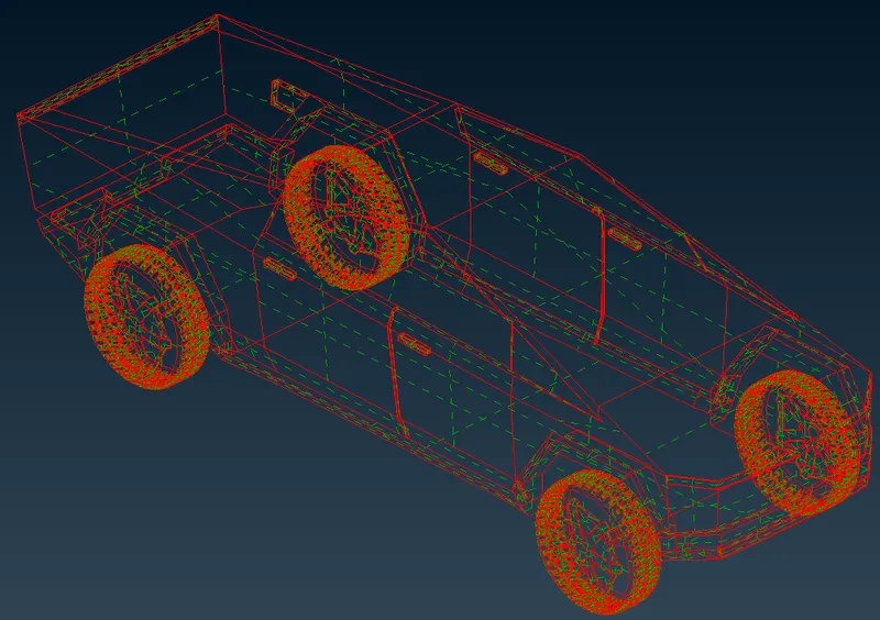
- We can see that the single cons and some missing surfaces are present, we have to resolve these errors to move forward towards meshing.
Step 3 - Topological cleanup
- In topo cleanup, we will solve all the errors and prepare the geometry for meshing.
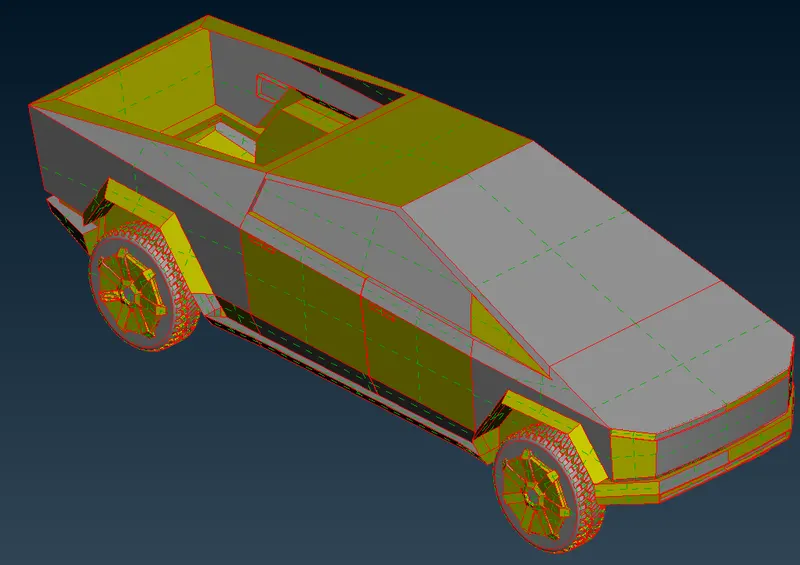
- We will run the topo option, which will solve some single cons.
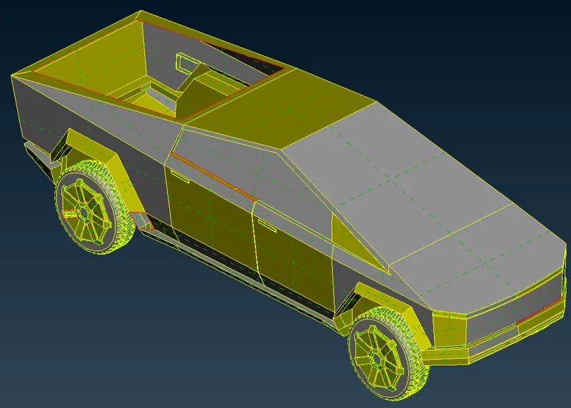
- Some elements of geometry are out of shape i.e. They are irregular. because of which we cannot select the proper elements for further operations on it.
- We can fix them using the fine option from the auxiliaries section under the topo deck, but it will take a lot of time.
- So instead, we will be using another method.
- Go to mesh deck and click on length under the perimeters section.
- A window pops up, select the perimeter option, and select the whole geometry.
- Do a middle click to confirm the selection.
- Enter the length as 1 and click on OK.
- Return to topo deck.
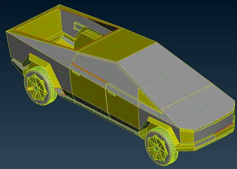
- Since geometry is symmetrical, we can delete half of it and only work on the other half.
- After solving all the errors, we can again have the other half by using the copy option.
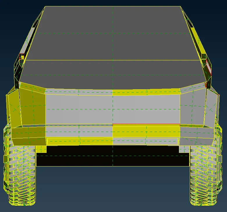
- We can't select the exact half of the geometry to delete because there are no double cons present which separate the surfaces in half.
- So, we will create the cons using the Cut option such that the geometry is divided exactly in half.
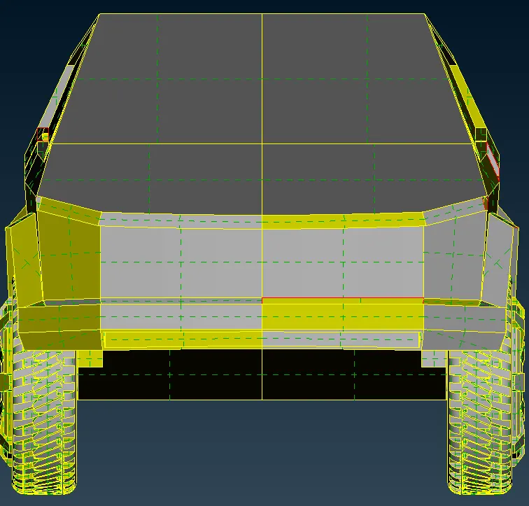
- We have created the double cons which separate the geometry in exact half.
- Now, to delete the half portion, click on the delete option and select the right half of the geometry as that portion has more errors.
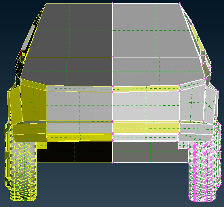
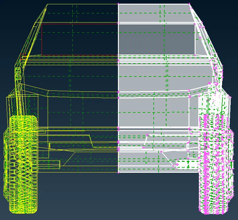
- Do a middle click to confirm the selection.
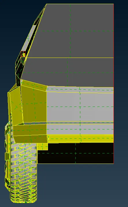
- Now we will work on this geometry to solve all the errors.
- We will fix all the missing surfaces first, this will also solve some single cons.
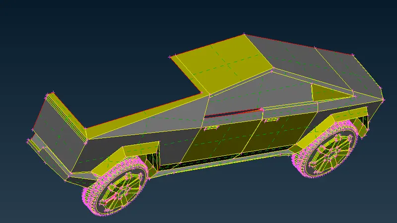
- Here we can see that some surfaces are missing; we will create new surfaces here using the coons option.
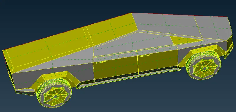
- We have fixed these missing surfaces using the coons option
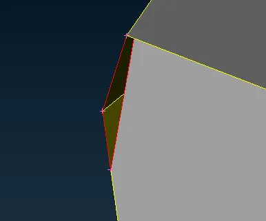
- We have one more missing surface which we will fix by deleting some surfaces and creating new surfaces here.
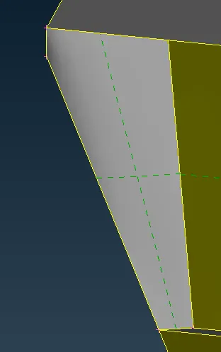
- We want to create a single volume for the whole geometry, so we have to merge every volume into one.
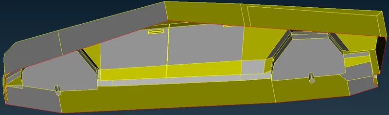
- We see that the shaft connects the wheels to the body.
- We will merge the volume of the shaft with the body and thereby also merge the volume of the wheels too.
- We will do this by deleting the extra surfaces and fixing any errors in the shaft which we come across in the process.
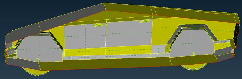
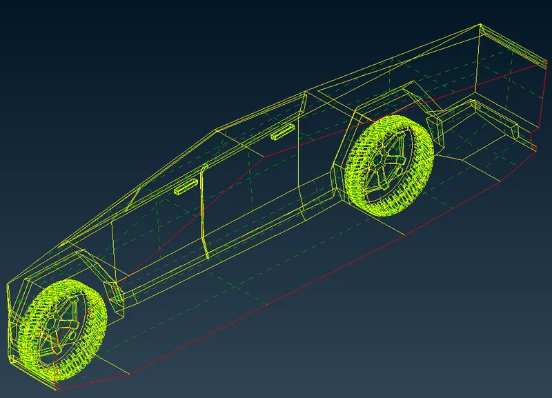
- We have merged and connected the volume of the tires, shaft, and body and now we have a single volume.
- We will run the geometry check and see whether we have any errors left.
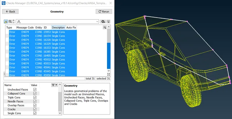
- We can see that the only errors we have are the single cons which are formed due to the deletion of the half symmetric part of the geometry.
- These errors will be fixed once the whole geometry is created i.e. When we make it symmetric again, we will ignore these errors for now.
- With this, we have completed the topo clean-up of the model.
Step 4 - Assigning PIDs
- Now we will assign the PIDs to the respective elements
- To assign PIDs, open the PID manager.
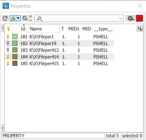
- We can see that there are already some PIDs assigned.
- We will create new PIDs named Body, Lights, Rims and Tires, windows, vault cover, and Shaft.
- To create a new PID right-click in the windows, go to New and then PShell, and click on PShell.
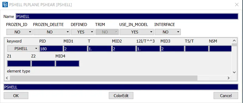
- Insert the Name as Body and click okay.
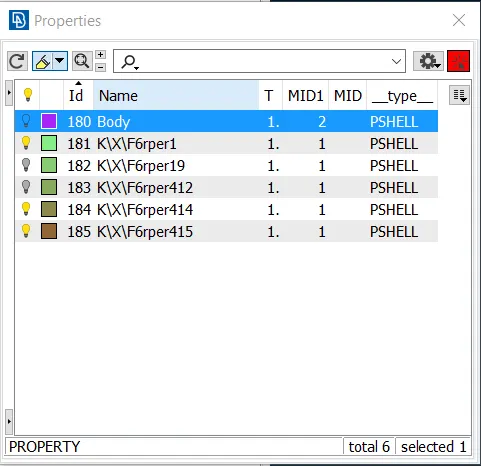
- A new PID by the name Body is created.
- In the same way, we will create all the other PIDs.
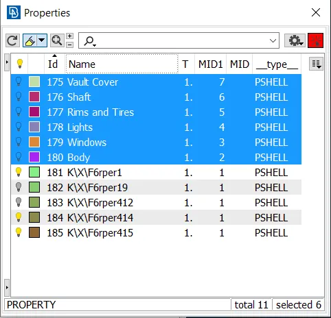
- Now we will assign them to the respective entities.
- We will first assign the windows PID.
- To assign we will Isolate the windows.
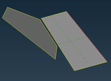
- In the property window right click on Windows PID and click on Apply
- Select the Windows entity and do a middle click to confirm the selection.
- Now we have successfully applied the Windows PID.
- In the same way, we will apply all other PIDs to their respective entities.
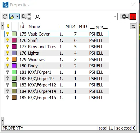
- After applying the PIDs, we have to make sure that we have not left any elements.
- We will select all the remaining PIDs and see whether we have any elements left.
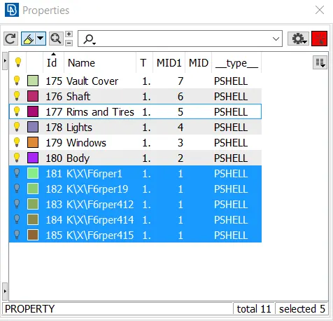
- Select all the remaining PIDs, right-click, and select show only.
- Press the F9 button to fit the geometry to the screen.
- We can see that there are no elements left out.
- We will delete these unnecessary PIDs now.
- Open the Compress option, and a window will pop.
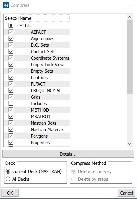
- Click on Okay, it will compress/ delete all the remaining PIDs which are not needed.
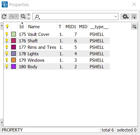
- We have successfully assigned the PIDs.
- Now we will move to the meshing process.
Step 5 - Checking the quality criteria before meshing
- Before we move to mesh, we have to decide the target length and make sure that the geometry meets the quality criteria so that the mesh developed is good.
- We will first deal with the Body PID.
- Isolate the body PID using the OR command and PID selection method.
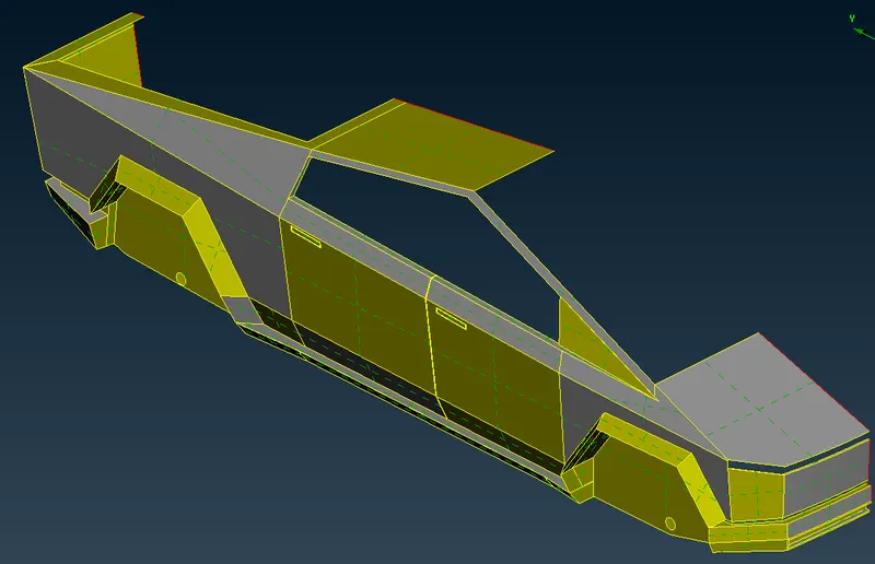
- Using the Cut option we will delete any cons which are too close to each other and are not necessary, also we can create new surfaces to improve the old ones.
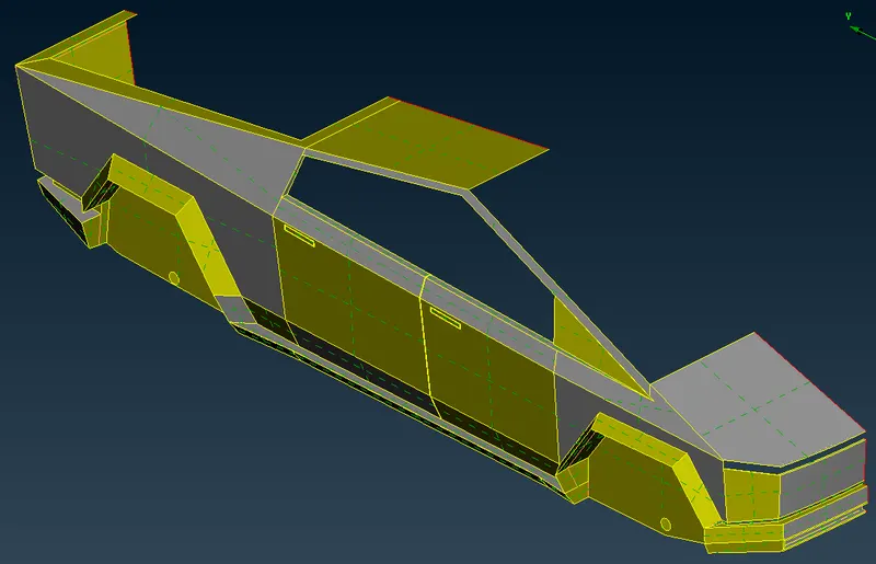
- We have deleted some cons, surfaces and have created new surfaces to simplify the geometry for meshing.
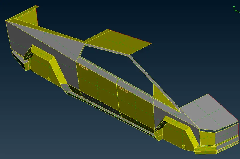
- Using the Measure tool we will measure the distance between the cons and nodes so that we will get to know the least dimension in the geometry.
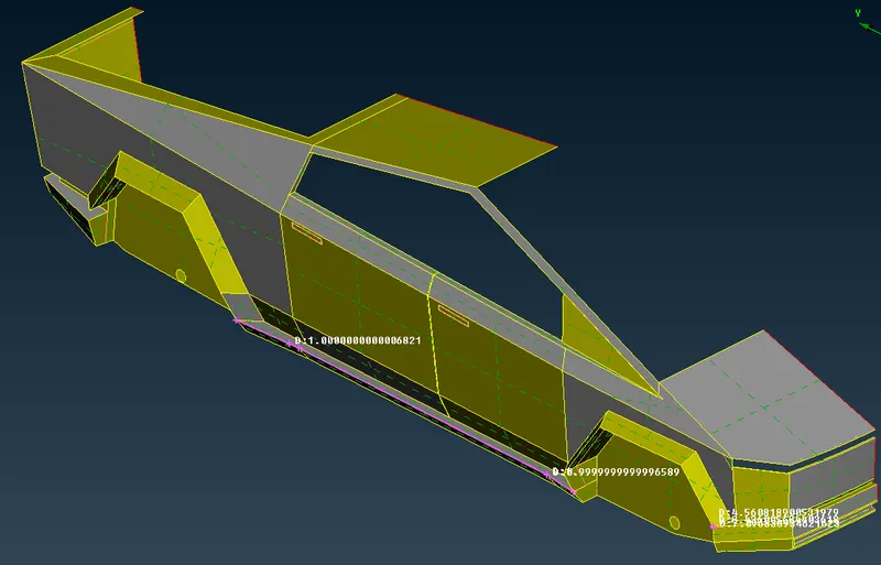
- After going through the dimensions, we will set the target length as 3mm, minimum length as 1mm, and maximum length as 5mm for the Body PID.
- Now we will inspect the Lights and determine the target length for the lights.
- We will isolate the Lights using the PID manager.
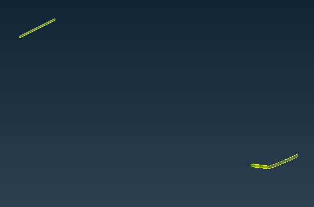
- Using the Measure tool, we will measure the distance between the cons and nodes so that we will get to know the least dimension in the geometry.
- After going through the measurement, we have decided to have a target length of 4mm, a minimum length of 2mm, and a maximum length of 5mm for the Lights PID
- We will isolate Windows for inspection.
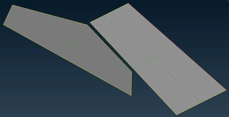
- Using the Measure tool, we will measure the distance between the cons and nodes so that we will get to know the least dimension in the geometry.
- After going through the measurement, we have decided to have a target length of 2mm, a minimum length of 1mm, and a maximum length of 3mm for the windows PID
- Now we will inspect the Vault Cover.
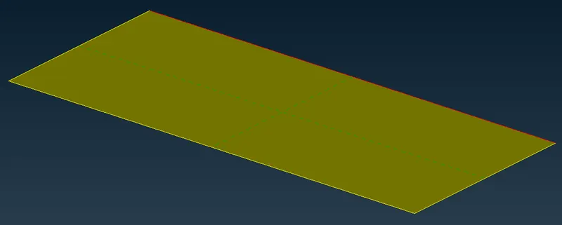
- After going through the measurement, we have decided to have a target length of 4mm, a minimum length of 2mm, and a maximum length of 5mm for the Vault Cover PID
- Now the only remaining PIDs are the Rims and Tires, and shaft.
- We will isolate the rims and tyres PID and Shaft PID.
- Since the shaft element is small, we will inspect it with the rims and tyres PID.
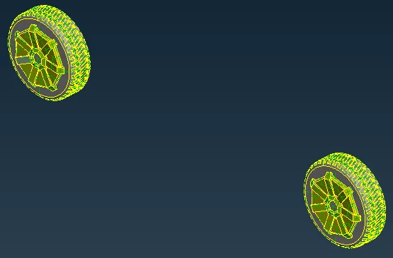
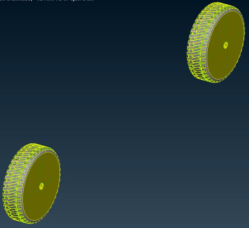
- using the Cut option, we will delete any cons which are too close to each other and are not necessary, also we can create new surfaces to improve the old ones.
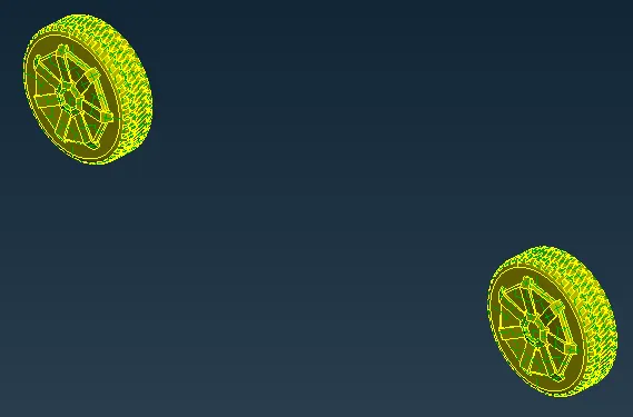
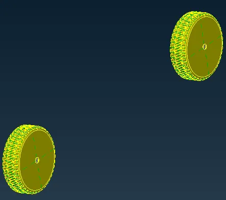
- Using the Measure tool we will measure the distance between the cons and nodes so that we will get to know the least dimension in the geometry.
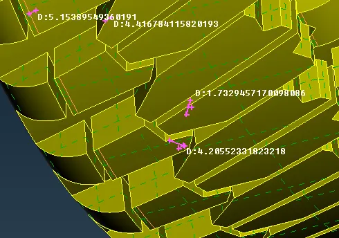
- After going through the measurement, we have decided to have a target length of 2mm, a minimum length of 1mm, and a maximum length of 3mm for the Rims and tires PID, and Shaft PID.
- Now we will move forward to Meshing.
Step 6 - 2D surface meshing
- For meshing, we will switch to a mesh deck and change the decks to OpenFOAM.
- Also, change the view to PID.
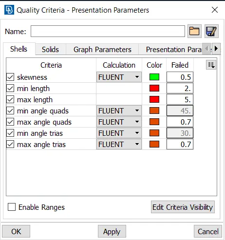
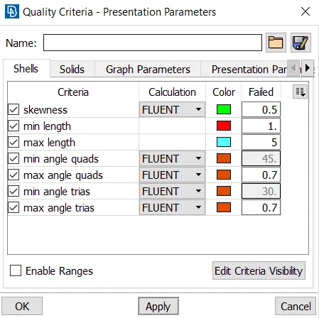
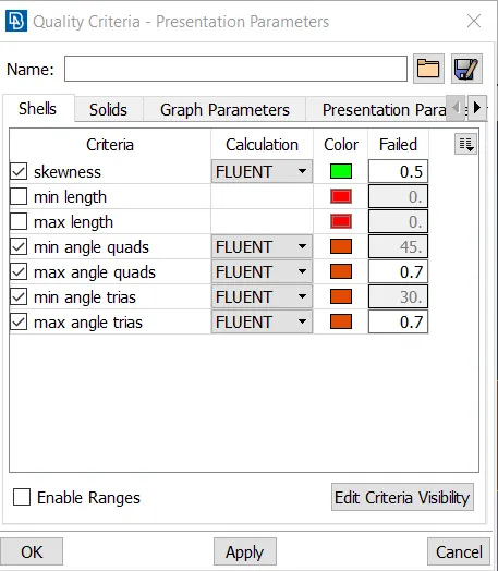
- Open the quality criteria parameters and set the parameters as below.
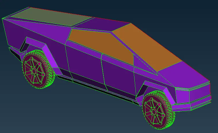
- We will turn off the shadow mode and enable the hidden mode.
- In the hidden mode, we can see the color codes of the quality criteria on the screen as well when we are done meshing, so we can fix any errors or the elements which don't come in the quality criteria.
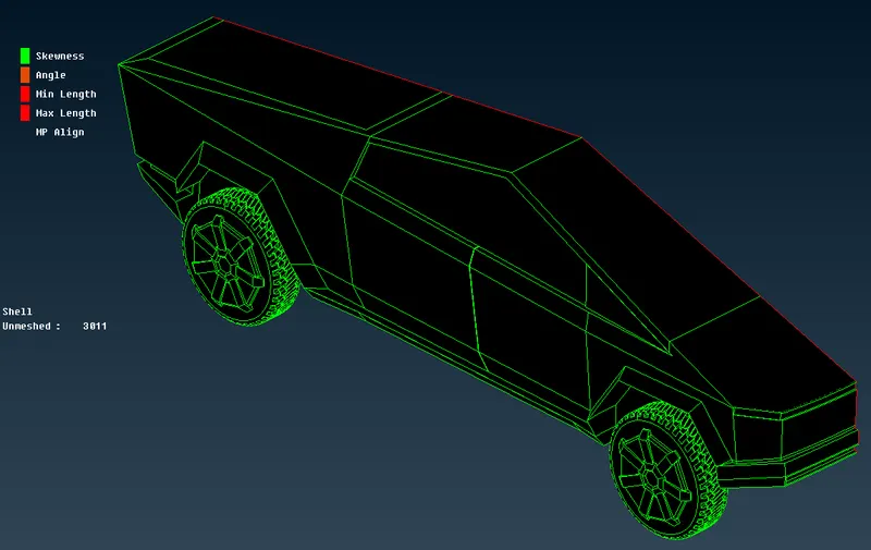
- Now we will start the meshing of the Lights.
- Isolate the Lights PID.
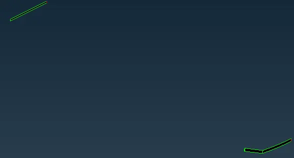
- Set the minimum length as 2mm and the max length as 5mm in the quality criteria parameters.
- In the mesh, parameter select Tria elements of 1st order and set the target length as 4mm, minimum length as 2, and max length as 5.
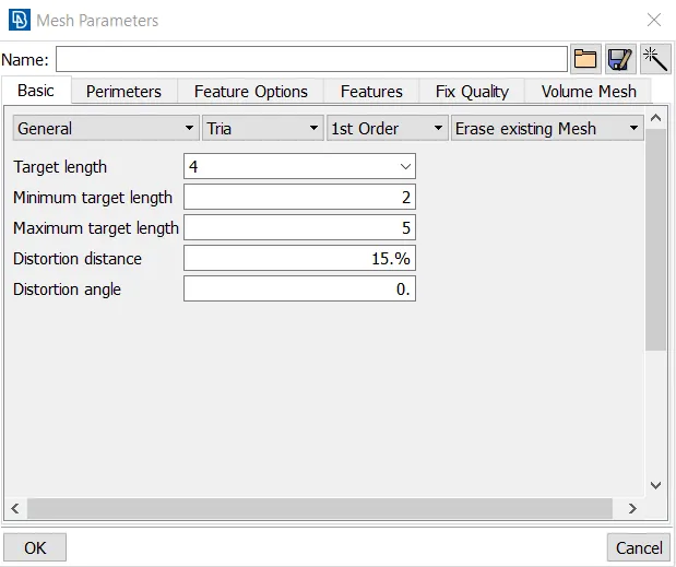
- Now click on the length option from the perimeter section under the Mesh deck.
- A window pops up,
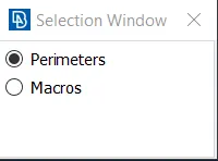
- Select the perimeter option and select the whole logo geometry using box select and do a middle click to confirm the selection.
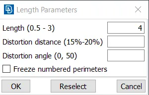
- Enter the length as 4 and click on okay.
- Now select the macros option and select the whole logo geometry, do a middle click to confirm the selection.
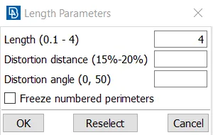
- Enter the length as 4 and click on okay.
- Click on spot mesh from the mesh generation section under the mesh deck.
- Select the whole geometry and do a middle click to generate the mesh.
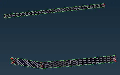
- We can see that there are about 137 elements that don't pass the quality criteria.
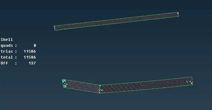
- To solve this, we will use the reconstruct option.
- Click on reconstruct option from the shell mesh section under the mesh deck and select the visible option so that all the elements on the screen are selected
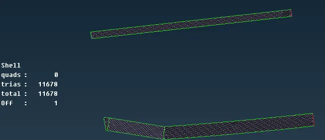
- Now we have only 1 Off element, we will solve it using the move option under the grids section in the mesh deck.
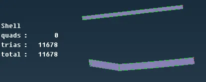
- We can see that all the Off elements are solved, and with this the meshing of the Lights is complete.
- We will mesh the vault Cover.
- Isolate the Vault Cover PID.
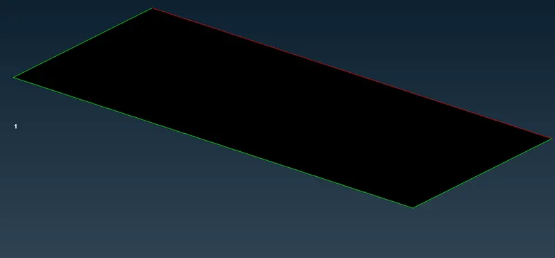
- Since the target length is the same as that of the Lights we won't have to change the quality and mesh parameters
- Now click on the length option under the perimeters section in topo deck.
- A window pops,
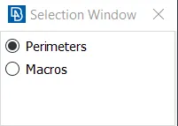
- Select the perimeters option, select the whole geometry and do a middle click to confirm.
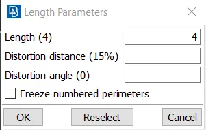
- Enter the length as 4 and click on okay.
- Select the macros option and select the whole geometry, do a middle click to confirm it.
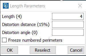
- Enter the length as 4 and click on okay.
- Now click on spot mesh and click on visible from the drop-down option to mesh the geometry.
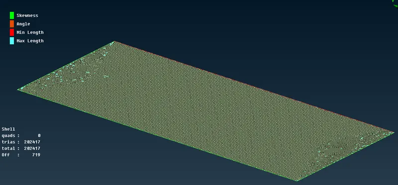
- We can see that there are about 719 off elements.
- We can use the reconstruct option here.
- Click on reconstruct option under the shell mesh section in the mesh deck.
- And select the visible option from the drop-down options to reconstruct the mesh.
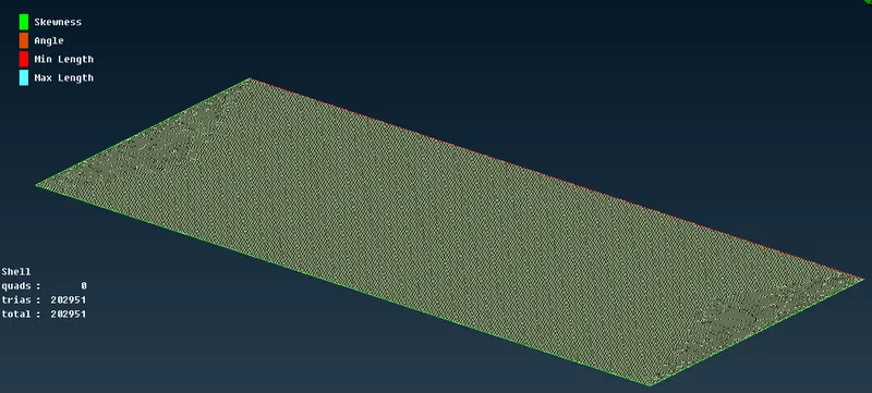
- We can see that all the Off elements are solved, and with this the meshing of the vault cover is complete.
- We will mesh the windows now.
- Isolate the windows PID.
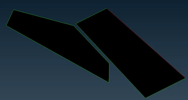
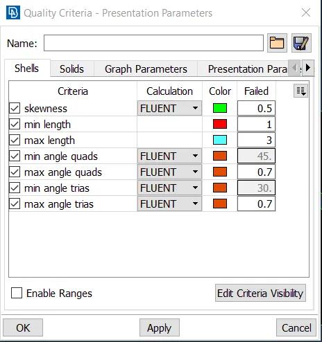
- Open the quality criteria and set the minimum length as 1mm and max length as 3mm
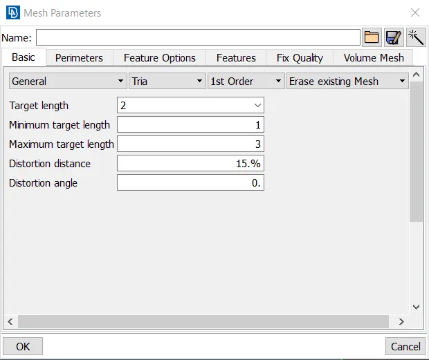
- In the mesh parameters select the trial elements of 1st order, set the target length as 2mm, min length as 1, and max length as 3.
- Click on the length option under the perimeters section in the mesh deck.
- A window pops up,
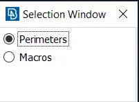
- Choose the perimeters option and select the whole geometry, do a middle click to confirm the selection.
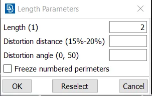
- Enter the length as 2mm and click on okay.
- Now choose the macros option and select the whole geometry, do a middle click to confirm the selection.
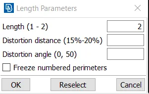
- Enter the length as 2mm and click on okay.
- Click on the spot mesh option under the mesh generation section in the mesh deck.
- Select the visible option to mesh the geometry.
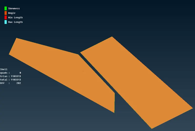
- We can see that there are about 282 off elements.
- We can fix this by using the reconstruct option.
- Click on the reconstruct option under the shell mesh and select the visible option to reconstruct the mesh.
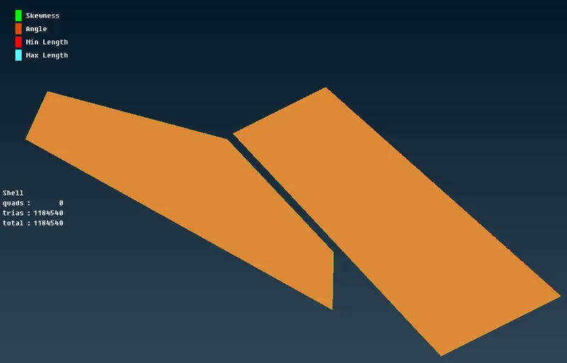
- All the off elements are fixed now.
- We will mesh the Rims and tyres along with the shaft.
- Isolate the rims and tyres PID and also the shaft PID.
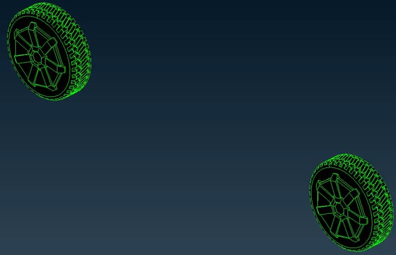
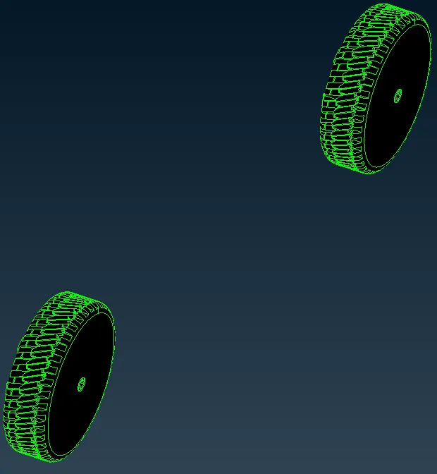
- The shaft element is small, so we will mesh it together with the rims and tires.
- Since the target length, the minimum and maximum length are the same as that of the window PID we won't have to change that.
- Click on the length option under the perimeters section in the Mesh Deck.
- A window pops up.
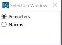
- Choose Perimeters and select the whole geometry, and do a middle click to confirm the selection.
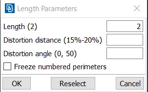
- Enter the lengths as 2 and click okay.
- Now choose Macros and select the whole geometry, and do a middle click to confirm the selection.
- Enter the length as 2 and click on okay.
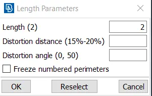
- Click on the spot mesh option under the mesh generation section in the mesh deck.
- Select the visible option to mesh the geometry.
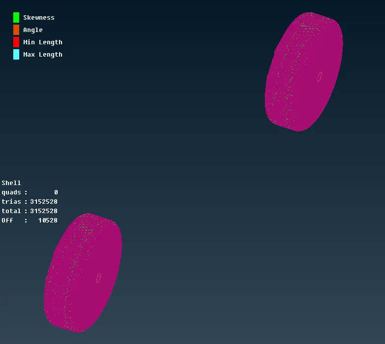
- We can see that there are a lot of off elements.
- We will fix these by using the reconstruct option.
- Click on reconstruct option in the shell mesh section in the mesh deck.
- Select the visible option to reconstruct the mesh.
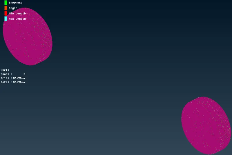
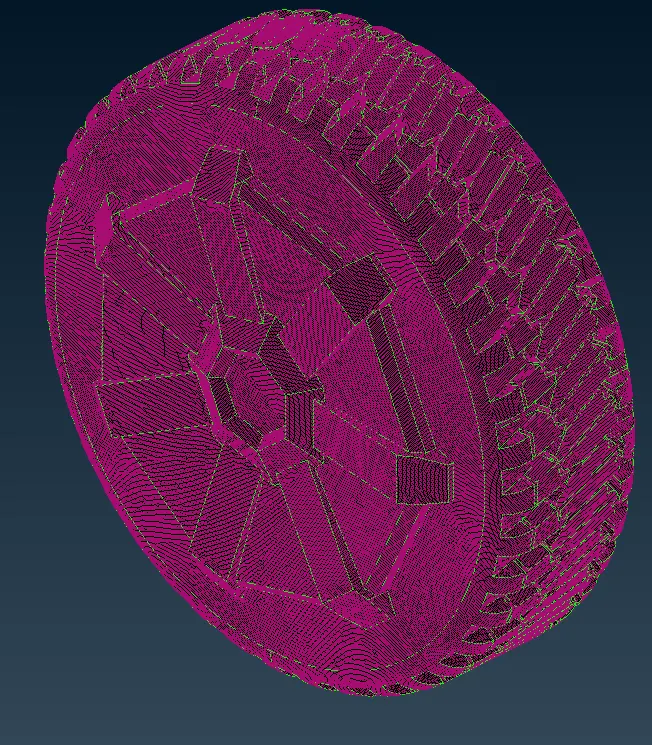
- After using the reconstruct option multiple times and using mesh editing tools we successfully reduced the off elements in the Rims and Tyres PID to zero and also in the Shaft PID.
- We will mesh the Body now.
- Isolate the body PID.
- Open the quality criteria and set the minimum length as 1mm and max length as 5mm.
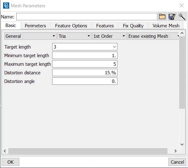
- Now open the mesh parameters.
- Select the Tria elements of 1st order, set the target length to 3mm, the minimum length as 1mm, and the max length to 5mm
- Click on the length option under the perimeters section in the mesh deck.
- A window pops up,

- Choose the perimeter option and select the whole geometry but exclude the cons which are shared by other PIDs
- Make all other PIDs visible by clicking on the ALL option, and do a middle click to confirm the selection.
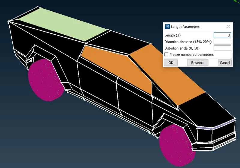
- Enter the length as 3mm and click on okay.
- Click on the spot mesh option under the mesh generation section in the mesh deck.
- Select the body and do a middle click to start the meshing.
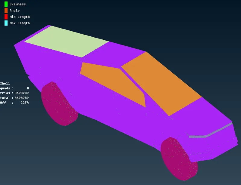
- We can see that there are a lot of off elements.
- We will fix these by using the reconstruct option.
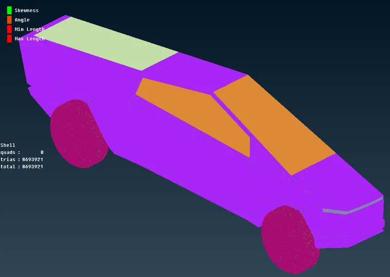
- We have fixed all the Off elements.
- With these, we have finished with the 2D meshing of the geometry.
Step 7 - Completing the geometry.
- We have only half the geometry of the Tesla Cyber Truck, so we have to create the other half to complete the geometry.
- Switch to the top view.
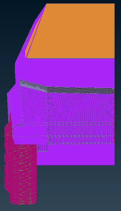
- Since the Tesla Cyber Truck model is symmetric that is why we deleted the other half of the geometry and worked on the half geometry only.
- Now we will copy this half geometry and paste it.
- Click on the drop-down arrow on the transform option.
- Choose copy, and select the whole geometry.
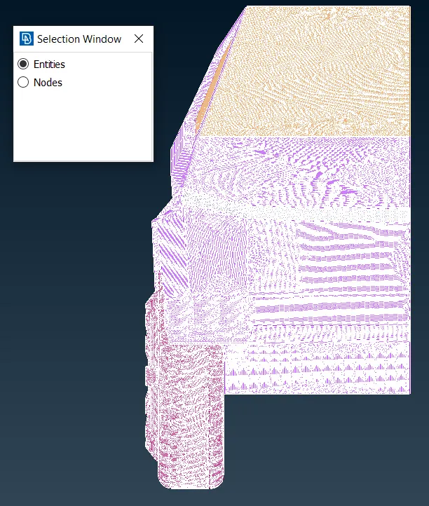
- Do a middle click to confirm the selection.
- A window pops up.
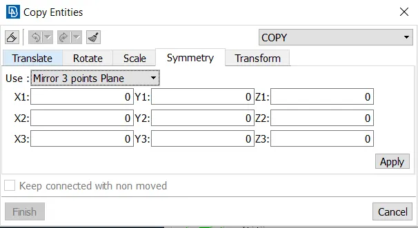
- Go to symmetry, and in the use section select mirror 3-point plane.
- In this, we have to select 3 points to define the plane.
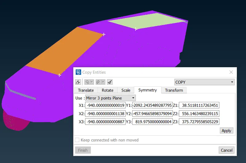
- After selecting the 3 points do a middle click to confirm the selection.
- A new window pops up.
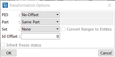
- In the PID section choose the No offset option since we don't want any offset between the geometry.
- Also, in the part section keep it the same part, so that it will have the same PIDs.
- click on okay to copy the geometry.
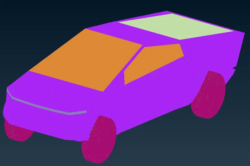
- The geometry is now completed.
Step 8 - Creating a wind tunnel.
- For aerodynamic analysis or CFD flow analysis over the Tesla Cyber Truck, we need a wind tunnel.
- So, we will create a virtual wind tunnel in the software.
- To create the wind tunnel, we will switch to topo deck.
- First, we need to measure the length of the tesla Cyber Truck, we will measure the length of the tesla Cyber Truck using the measure tool.
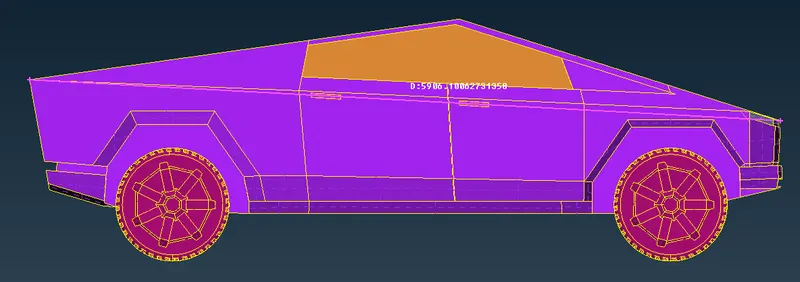
- We can see that the length of the Tesla Cyber truck is 5906.1006 which we can round off to 5910.
- We will switch to ENT viewing mode
- Before we start creating the surface we have to define/ create some points, which will later act as nodes for creating cons, and then surface
- We will create a point in the middle of the bottom surface.
- To create the point, click on the relative option under the points section in the topo deck.
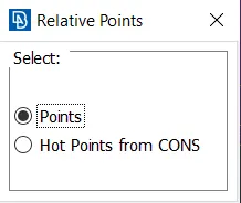
- A window pops in that select Points, and place the point in the geometry.
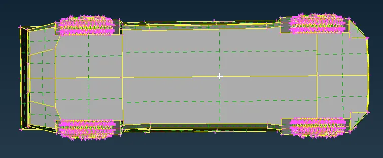
- Do a middle click to confirm the point location. a window will pop.
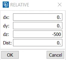
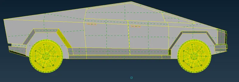
- We want to place the point below the geometry such that the wheels won't touch the surface of the wind tunnel.
- Since our area of interest lies above the geometry, we will keep less gap between the bottom surface and the geometry.
- To place the point below the geometry we will insert the value in the z-axis coordinate.
- In the dz insert the value as -500. here minus sign indicates that we have to place the point below the geometry.
- Now the next point will be in front of the Truck.
- The distance from the Truck to the point is expected to be 4 times the length of the car.
- For that, we have to measure the length from the center to the front of the Tesla Cyber Truck and then add it.
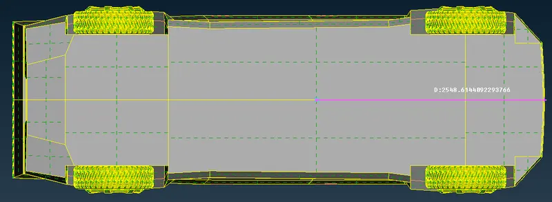
- From the center to the front of the Truck is 2548.6144 which can be rounded off to 2550.
- So, the total will be 2550 + (4 x 5910) = 26190
- Using the same method, we will place a point at a distance of 26190 from the previous point.
- Only this time the value will be inserted in the dy and it will be negative.

- Now we have to place a point in the rear of the Tesla Cyber Truck.
- The distance from the rear of the Truck to the rear point will be 6 times the length of the car.
- But we also have to add the distance from the center of the Truck to the rear of the Truck.
- We will measure this using the measure tool.
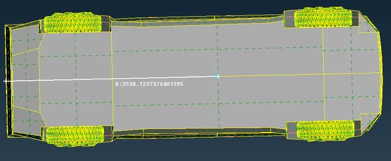
- The distance from the center of the Tesla Cyber Truck to the rear of the Tesla Cyber Truck is 3538.1237 which can be rounded to 3540.
- So, the total will be 3540 + (6 x 5910) = 39000
- We will use the same method to place the rear point at a distance of 39000 from the previous point.
- This time we will enter the value in dy and the value will be positive.

- Now we have to create points on the side of the geometry.
- The side distance is equal to the length of the Tesla Cyber Truck.

- Now we will create the bottom surface, but for that, we must create curves first.
- We will use the create option in the curves section to create curves.
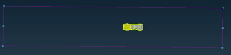
- Now that we have created the curves we will use the Fitted option to create the surface.
- While creating the surface it asks for the PID.
- Since we have not created the PID for the wind tunnel we have to create a new one.
- We will create a new PID with the name BaseSurface Tunnel.
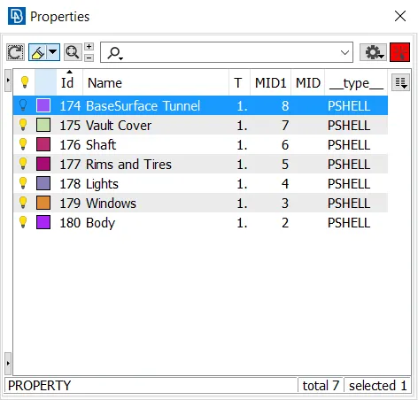
- We will assign it to the newly created surface.

- Now we will offset the bottom surface to the top to create the top surface.
- For that, we will measure the distance from the bottom surface to the roof of the Tesla Cyber Truck first.
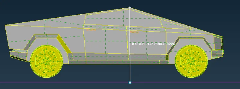
- We can see that the distance from the bottom surface to the roof is 2031.1469 which can be rounded off to 2032.
- So, the top surface will be 3 times the length of the Tesla Cyber Truck from the roof of the car.
- That is 2032 + (3 x 5910) = 19762
- To offset the surface, click on offset in the faces section under the topo deck.
- Select the surface and do a middle click to confirm the selection.
- A window pops up, enter the offset distance as 19762 and click on okay.
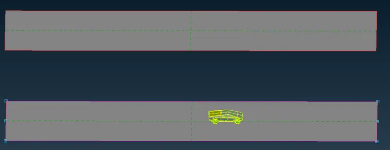
- Now that we have created the top surface, we won't need the points and the curves so we will delete those.
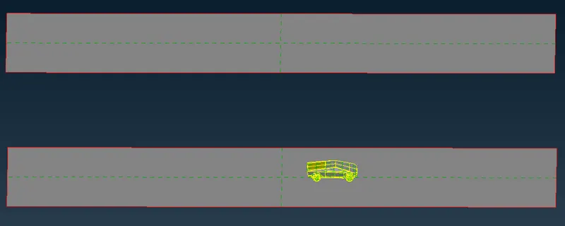
- Now we will create the side surfaces using the Fitted option.
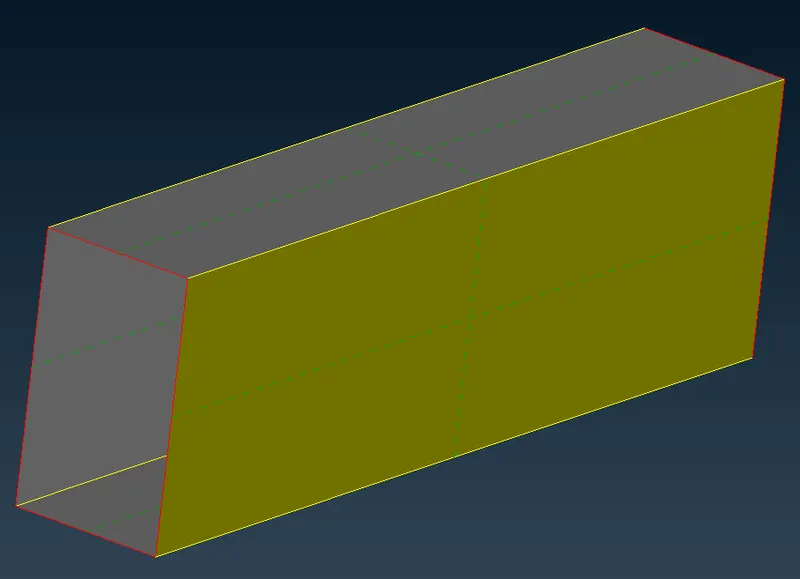
- In the same way, we will create the front and rear surface
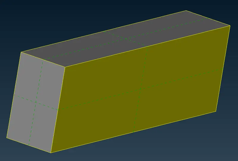
- Now we have to assign PID to the wind tunnel surfaces.
- We will create a total of 4 new PIDs named FrontFace Tunnel, RearFace Tunnel, SideFace Tunnel, and TopFace Tunnel.
- we will apply it to the respective surfaces.
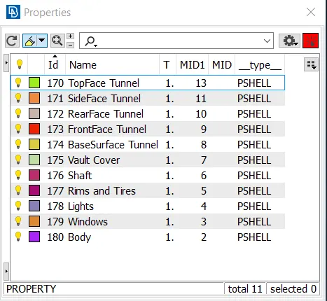
Step 9 - Meshing the wind tunnel.
- We will switch to a mesh deck to mesh the geometry and change the viewing mode to PID.
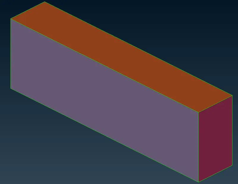
- We will need finer mesh near the car whereas we can have a coarse mesh away from the car.
- For now, we will disable the min length and max length in the quality criteria.
- click on the length option under the perimeter section in the mesh deck.
- in the window choose perimeter and select the top face.
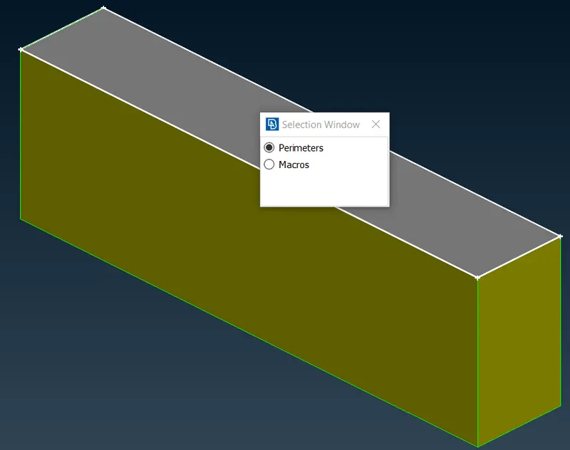
- Do a middle click to confirm.
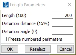
- Enter the length as 200 and click on okay.
- Do the same for the macros as well.
- Now choose the perimeter option and select the bottom face.
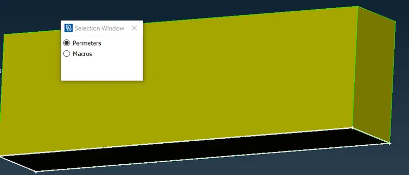
- do a middle click to confirm the selection.
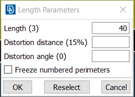
- Enter the length as 40 and click on okay.
- Do the same with the macros option.
- We have to give varying mesh lengths.
- For that click on the spacing option under the perimeters section in the mesh deck.
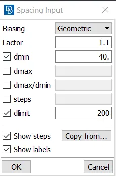
- In the windows, select the biasing as a geometric, factor as 1.1, the dmin as 40, and dlimit as 200.
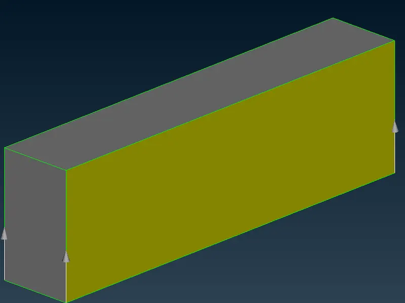
- Select the cons such that the arrow is pointed towards the top surface.
- Click on okay to confirm the selection
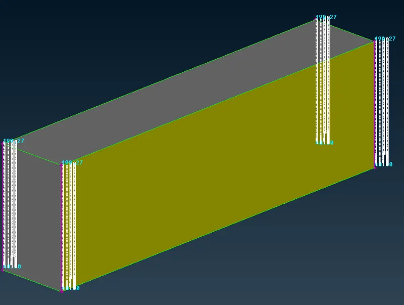
- Now we can go forward and create the mesh.
- We will isolate the base surface.
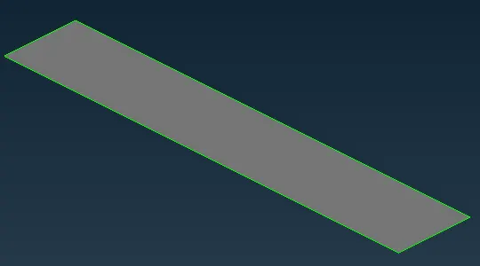
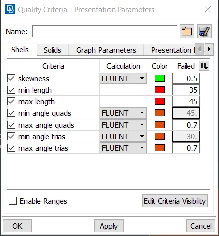
- In the quality, the criteria give the min length as 35 and the max length as 45.
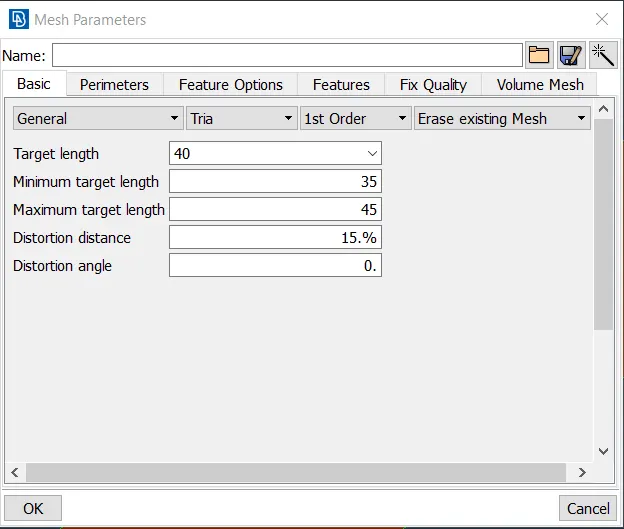
- In the mesh parameters, give the target length as 40, the min length as 35, and the max length as 45.
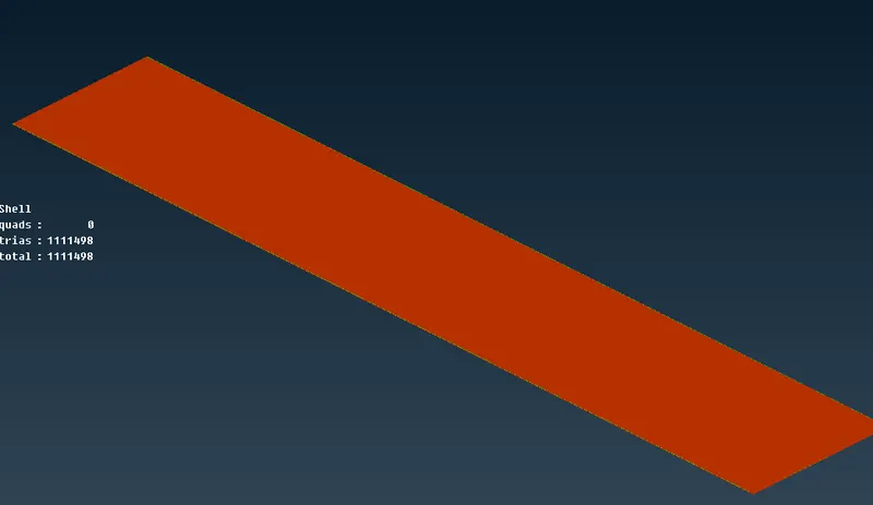
- Now click on spot mesh in the mesh generation section under the mesh deck.
- Click on visible to mesh the base surface.
- Now we will isolate the top surface.
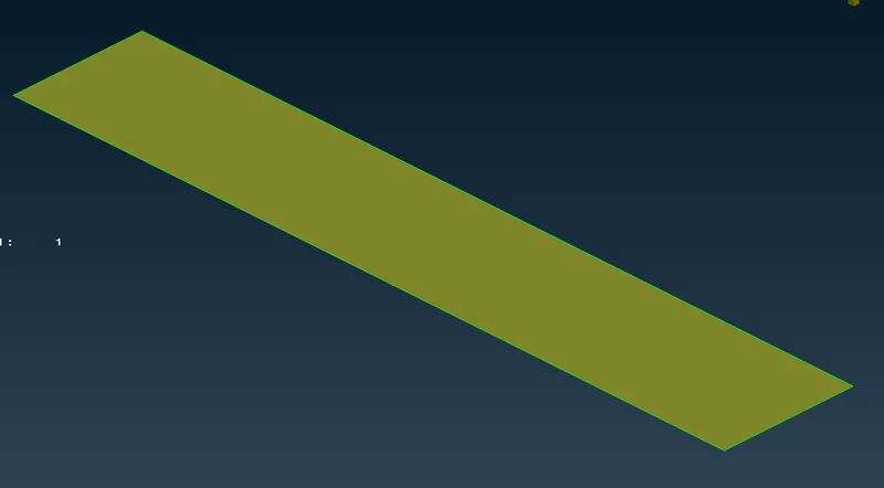
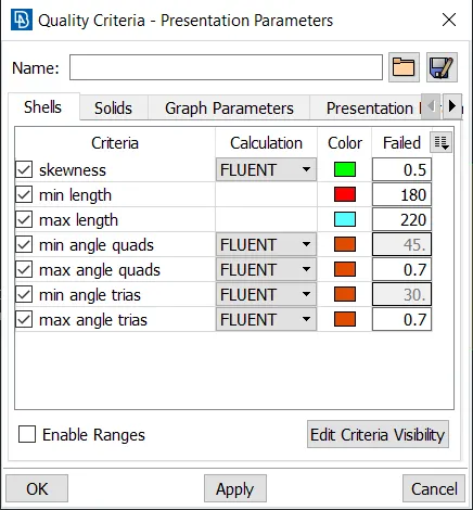
- In the quality, criteria insert the min length as 180 and the max length as 220.
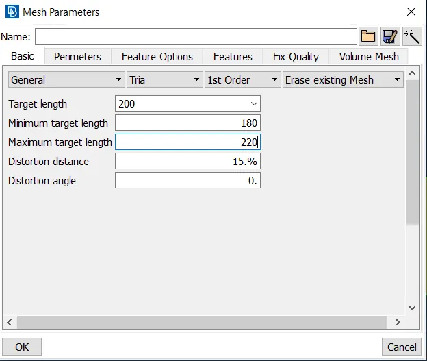
- In the mesh, parameters insert the target length as 120, min length as 100, and max length as 140
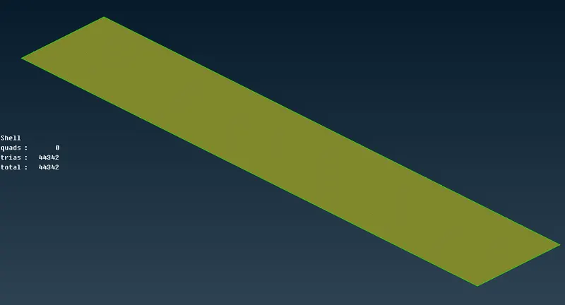
- Now using the spot mesh option to mesh the top surface.
- Now make the wind tunnel visible.
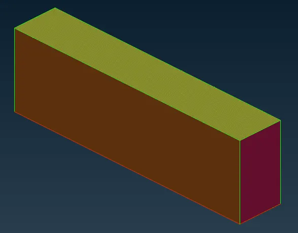
- In the mesh, parameters change the target length to local.
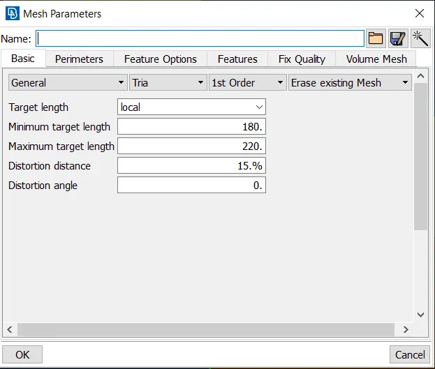
- Now we will mesh the remaining surfaces one by one.
- First, we will mesh the rear face surface by using the spot mesh.
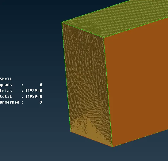
- Now we will do the same to the front face surface.
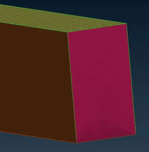
- We will mesh the side faces now.
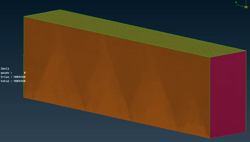
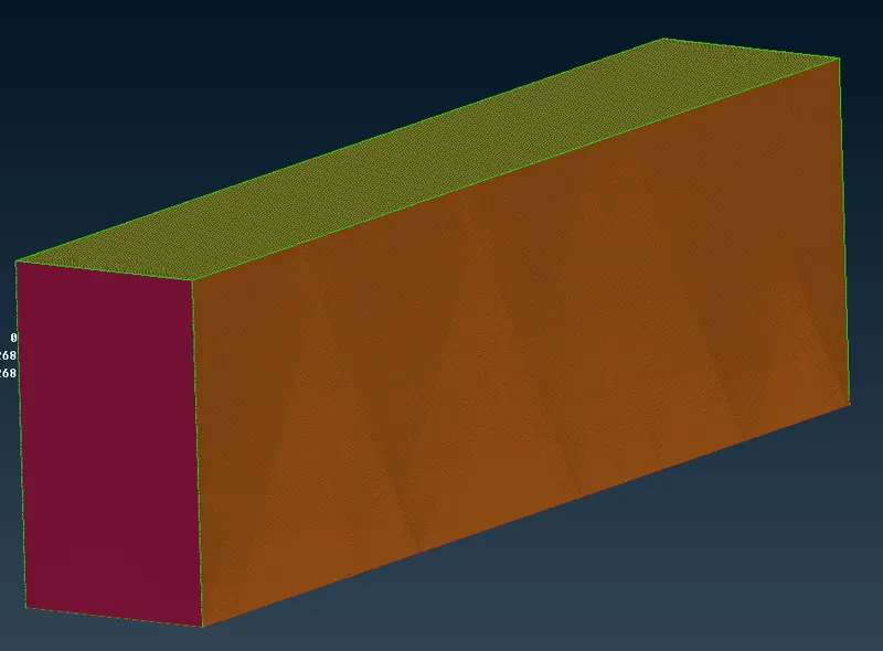
- now we are done with the surface meshing.
Step 10 - Volumetric meshing.
- To perform volumetric mesh, we will switch to the Volume mesh deck.
- First, we have to define all the volumes.
- To do so click on the Define option under the volume section in the volume mesh deck and select Auto Detect.
- A window pops,
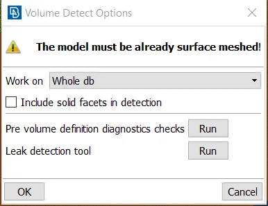
- Set the work on to the whole db, and click on ok.
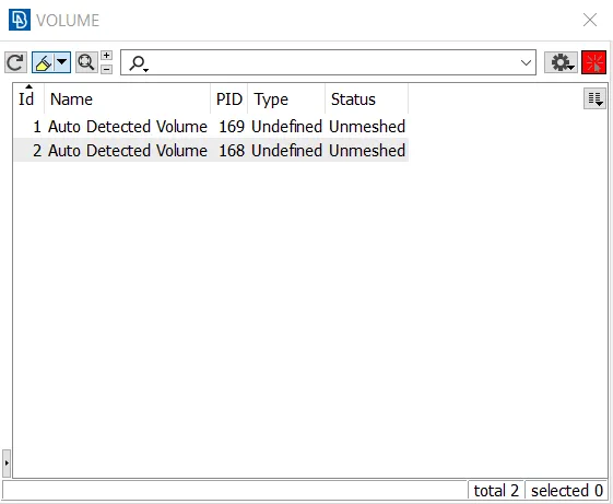
- In a new window, it will show all the volumes detected.
- We got 2 volumes here which was as expected.
- The first volume is between the wind tunnel and the tesla Cybertruck
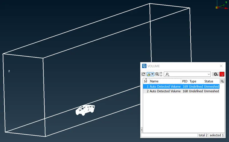
- the second volume is of the Tesla CyberTrust
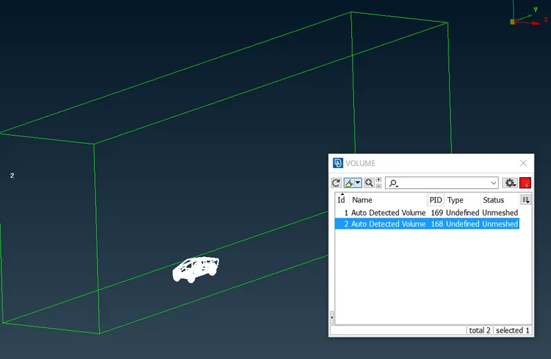
- We will only keep the volume that is between the wind tunnel and the Tesla Cyber Truck and delete the tesla cyber truck volume.
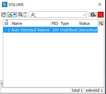
- Now we can perform the volumetric meshing on this volume.
- To perform the volumetric mesh, we have to right-click on the volume and click on the Remesh option.
(I have not gone ahead with the Remesh option because my System is not that powerful and volumetric mesh takes around 2 days).
- We have successfully completed the CFD meshing of the Tesla Cyber Truck.
Learning Outcome: -
- I successfully carried out the CFD meshing of the Tesla Cyber truck.
- I performed volume extraction that is to define volume.
- I gave the variable mesh length using the spacing option.
- I successfully performed the topo clean-up of different geometries, assigning PIDs, and copying the geometry to make it symmetrical.
- I created geometries from the reference points and also created the reference curves/points.
- I effectively checked the quality criteria of the mesh elements and also repaired/fixed them.
- I efficiently used the different mesh modifying tools to fix OFF elements.
Result: -
- The total number of Tria elements in the Body PID is 8247607
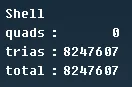
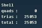
- The total number of Tria elements in the Lights is 25053
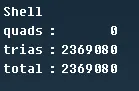
- The total number of Tria elements in the Window is 2369080
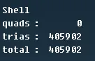
- The total number of Tria elements in the Vault Cover is 405902
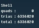
- The total number of Tria elements in the Rims and Tyres is 6336020
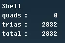
- The total number of Tria elements in the Shaft is 2832
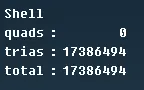
- The total number of Tria elements in the Tesla Cyber Truck is 17386494
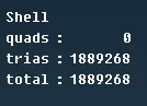
- The total number of Tria elements in the Wind Tunnel is 1889268
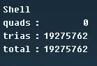
- The total number of Tria elements in the whole geometry is 19275762
(Since the volumetric mesh is not completed due to a lack of system capabilities, the elements in the volumetric mesh are not mentioned.)
Conclusion: -
- Topo clean is done to get rid of the single cons and to fix any errors in the geometry such as missing surfaces.
- Some small surfaces were modified to simplify the geometry
- Target length is selected based on the minimum distance between two cons or nodes in that geometry so that the geometry is captured perfectly while meshing.
- A single Volume is formed for the Tesla Cyber Truck because the volume of the tyres is connected to the body by the shafts.
- Quality errors are fixed using the reconstruct mesh option and if that does not work, the mesh elements are fixed manually using the fix, move, split option.
- To reduce the work required for topo clean up half of the geometry is considered since it is symmetrical, and after the meshing, it is copied and the whole geometry is completed.
- Overall, the CFD meshing of the Tesla Cyber Truck was completed successfully.
https://drive.google.com/file/d/1vDyL8VGiboGG4kSkZtFXyvxESjGQRIVB/view?usp=sharing