Week 3 Challenge : CFD meshing on Turbocharger
AIM:-
Generate the CFD meshing a turbocharger
OBJECTIVE:-
The main objective of the given challange is to perform surface mesh and volume mesh on turbocharger and also geometry clean up with the surface mesh for the PID.
Perform surface mesh with the given target lengths as per PIDs.
- Blade stage-1 = 1 mm
- Blade stage-2 = 1 mm
- Impeller = 2 mm
- Shaft rotor = 1 mm
- Turbo casing = 5 mm
- Compressor casing = 5 mm
- Inlet casing cover = 5 mm
PROCEDURE:-
- First of all impoert the model files.
- Check the geometry errors.
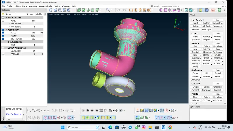
- For refine the error select the delete option and deleting the overlapping parts to improve the mesh quality.
- Aftert deleting the overlapping surface correct the triple cons and sigle cons as per requirement.
- Then check the error by using the wire frame command.
- Then check the blade impellar and shaft errors.
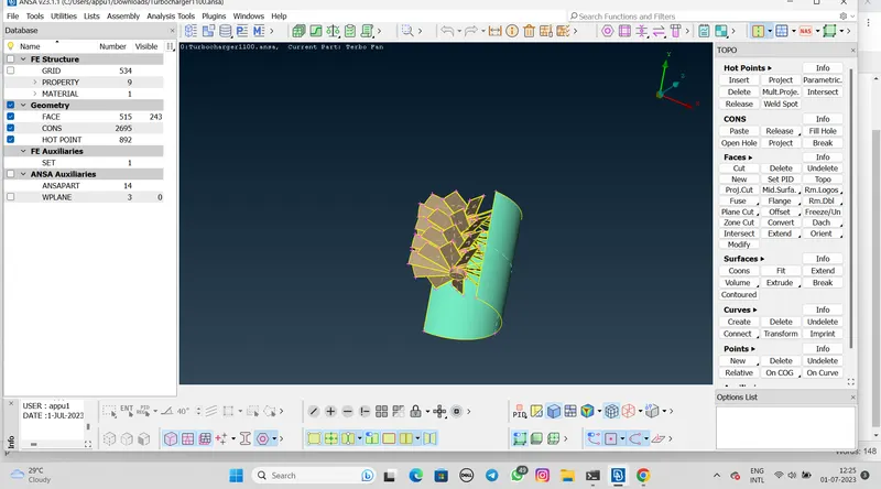
- Here check the two surface overlapping.
- Then delete the overlapping surface.
- After that check the model using the wireframe command to any sigle or triple cones are present or not.
- After that impeller surface clean and delete the extra surface.
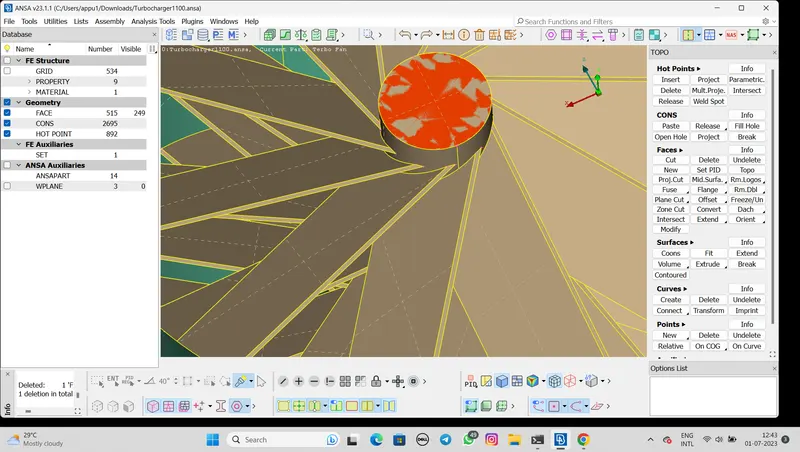
- Then refine the other bottom part of clearing the triple and single cones using the coons and fill hole option.
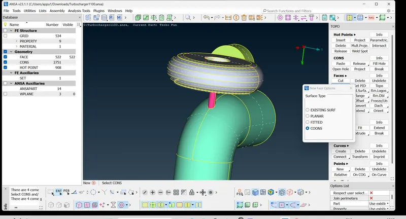
- Now Check the inner shaft and blades triple or single cons error and if there are error then clear them and make a refine model.
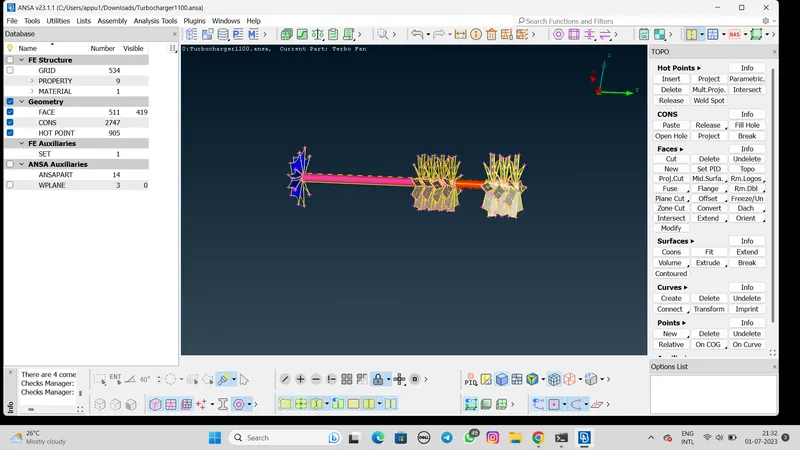
- Then rename the PID for that,Go to properties>There are default proporties
- Create the different parts newPID set the new PSHELL>give the name in the box.
- We can also change the color of the parts.
- Then delete empty PID which has no surface.
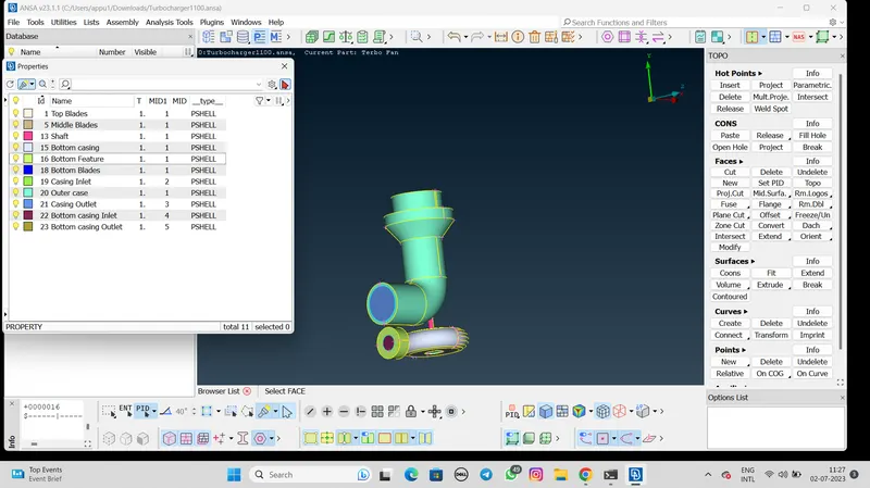
- After check all the error and rename procedure we go to meshing.
surface Mesh:-
- For the mesh procedure we need to mesh each component as per given length so we can mesh the component individually.
- Enter the quality criteria and mesh parameter and length of the mesh accordingly for each component.
- While the enter length also enter the Tria type for meshing.
- After the mesh generated we can see the Tria type mesh.
Compressor casing mesh:
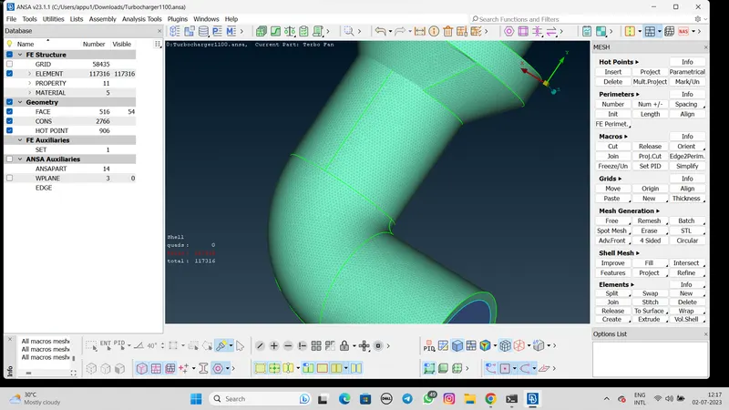
Turbocharger Mesh:
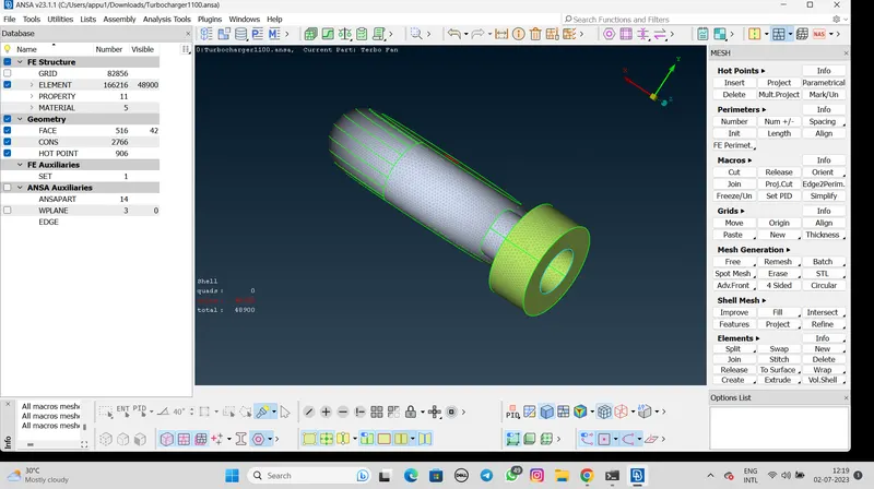
Impeller Mesh:
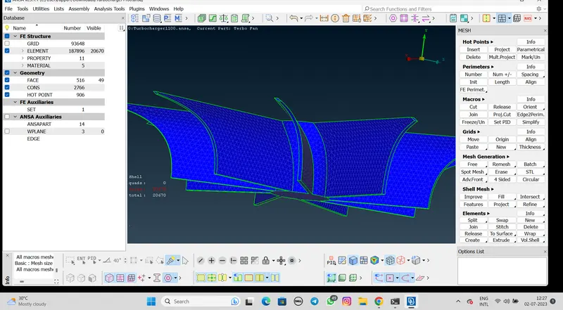
Shaft and Blades Mesh:
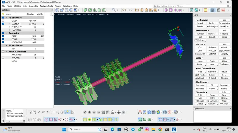
Volumetric Meshing:-
- To the volumetric mesh select the volumetric mesh option.
- Then select the Define option and select the Detect on the whole db option.
- After that we can see the unmeshed boundary.
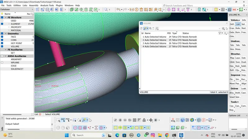
- Then select the Mesh option on the unmesh and select the Tetra CFD option.
- Convert the all unmeshed into the Tetra CFD mesh.
- After that the all procedure we can start the volumetric mesh.
CONCLUSION:-
- We generate the geometry with all the inlets and outlets closed to create a closed volume.
- We renamed the PDI.
- Surface meshing is done with different mesh length as per criteria.