Week 3 Challenge : CFD meshing on Turbocharger
Aim:
To perform Volumetric mesh in the given raw model of turbocharger.
Apply different mesh lenth for different PID's
Surface with the tria elements to make ensure the elements to 2D to 3D mesh
Mesh Length for various components:
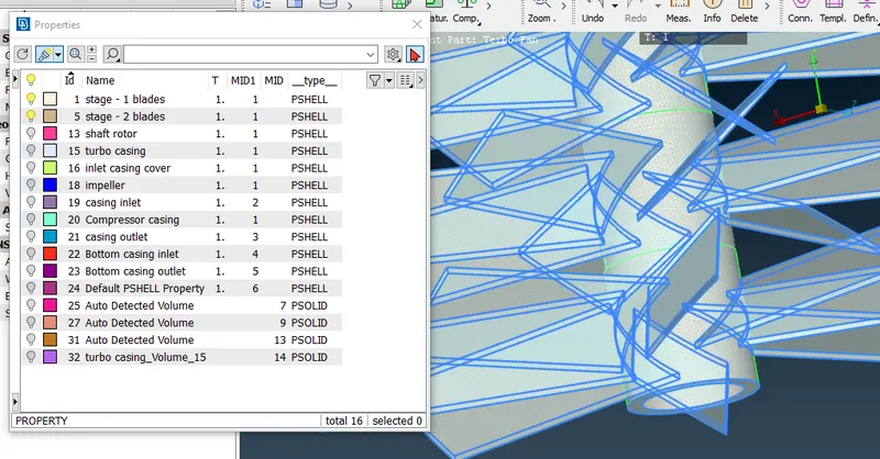
1) Blade stage 1 = 1mm
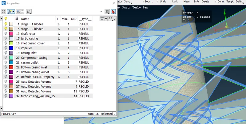
2) Blade stage 2 = 1mm
3) Impeller = 2mm
4) Shaft rotor = 1mm
5) Turbo casing = 5mm
6) Compressor casing = 5mm
7) Inlet casing cover = 5mm
Procedure to topo cleanup:-
1.Import the raw model to the ANSA
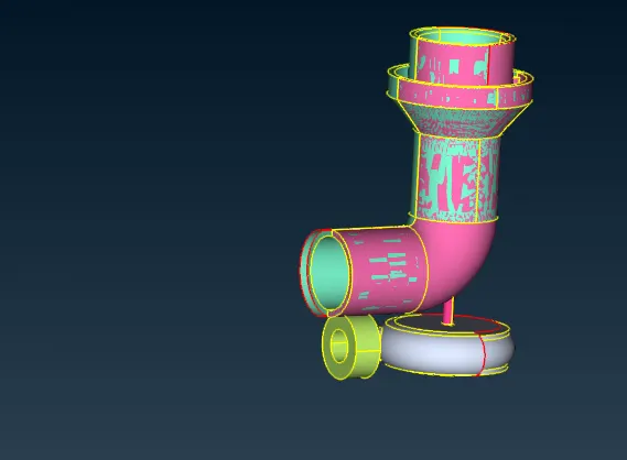
2.correct the top cleanup
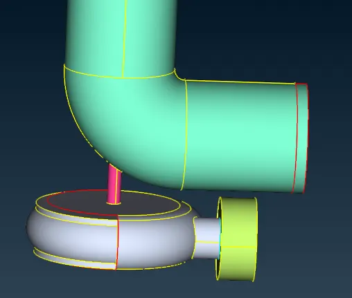
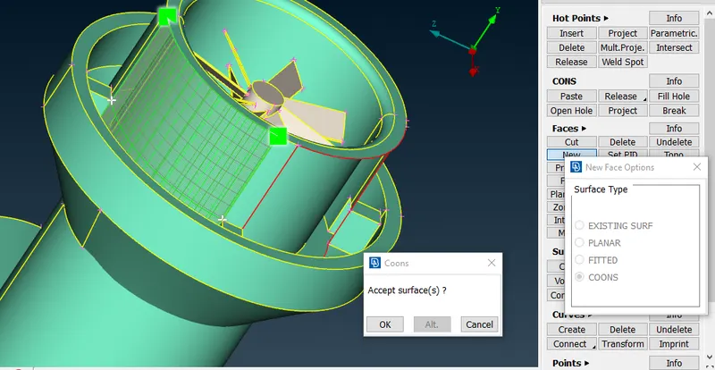
3.check for overlap surface with the given model
4.select PID to see the overlap surface
5.overlap surface are looks like pink colour, Select the surface by using PID Region and the delete the surface
6.Make ensure all overlapping surface are removed
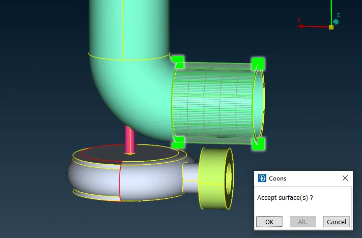
7.Create the new surface wherever it required and select the all single cons in there and select the face to create surface
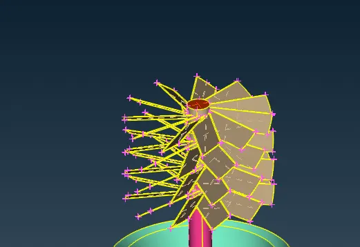
top blades
------------------------
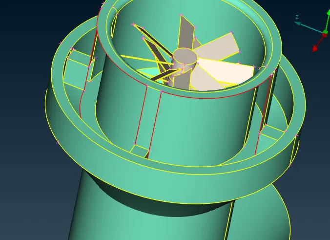
1. check for glitching in top surface near the stage 1 blades
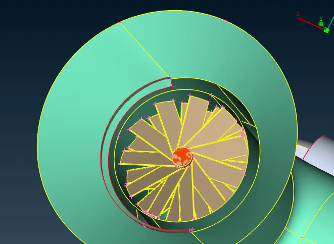
2. Remove the duplicate surface in there
3. Select the multiproject option to create the hoptpoints to patch in the face which required
4. Select the hotpoints individually to create surface
5. remaining are rectangle face to cover the face by using fillhole option and check for preview if the selection are correct, then create new surface
6. fill the remaining surface
7. Check for single cons in the top surface
8. Hide the unnessary surface by using not option
9. check the single cons in the stage 2 blades surface by isolating it.
10. Surface are penetrating with each other, but the faces are not joined
11. By using intersecting option we can choose the primary and secondary surface to intersect
12. triple cons are formed in the surface, delete the penetration surface
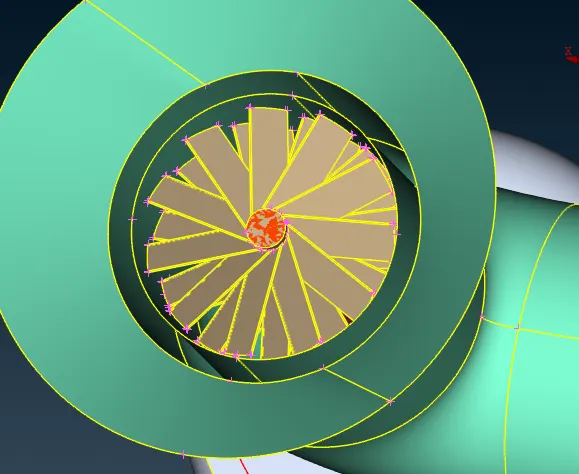
13. by using release option we can remove the triple cons in that surface
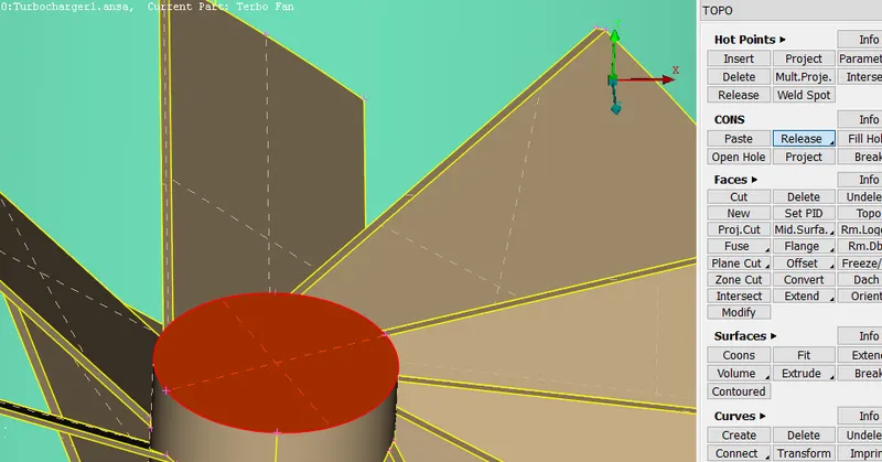
14. by using topo we can create the double cons in that surface
Turbo casing:
--------------------------------
1. casing needed to be in closed surface
2. by using parametric option with the value of 0.5
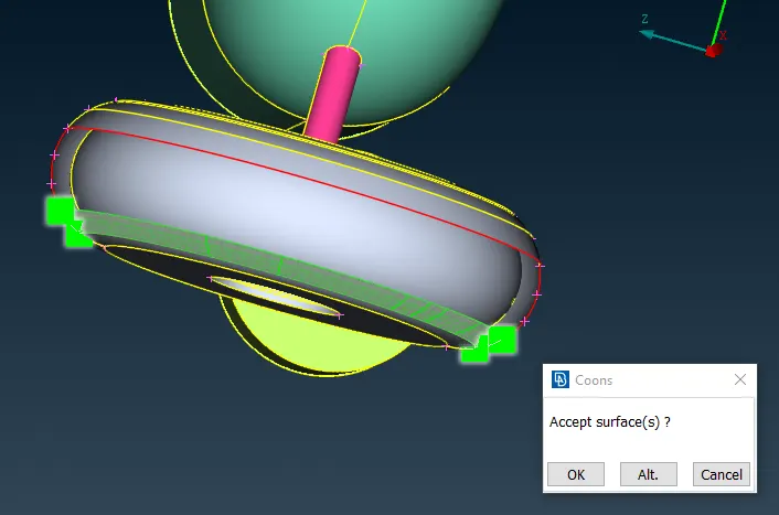
3. create the hotpoints by selecting the surface with the number of 14
4. Create the surface by selecting coons option and select the entities to patch up to cover the surface of casing
5. to remove the overlapping surface
6. cut the surface patch up with shaft
7. check geometry errors for single cons and triple cons
Properties:
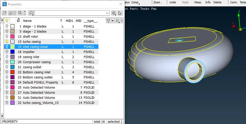
- PID Assign:
Turbo casing
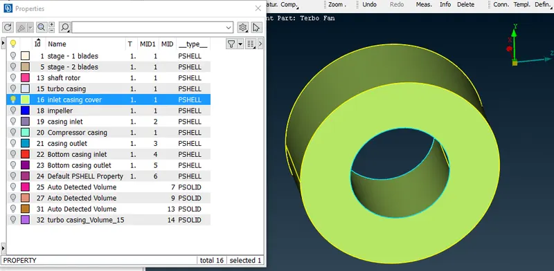
Inlet casing cover
Blades
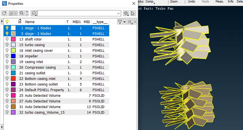
Shaft rotor

compressor casing
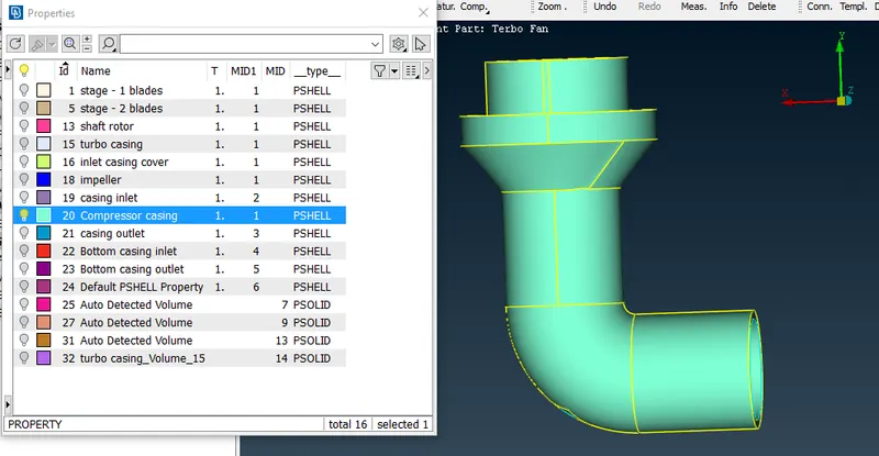
impeller
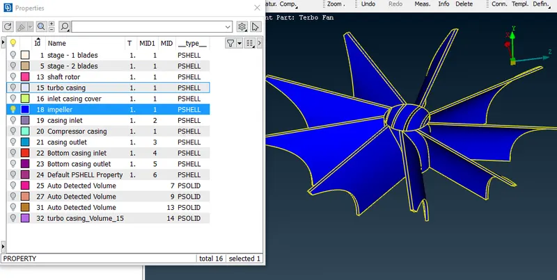
Bottom casing inlet & outlet
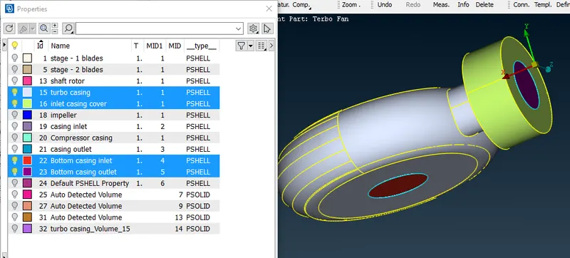
- Meshing:
Quality criteria:
-----------------
min lengt: 3mm
max length: 7mm
Mesh parameters:
target length: 5mm
minimum target length: 3mm
maximum target length: 7mm
Mesh Length:
Parameters: 5 mm
macros: 5mm
compressor casing
Casing inlet & outlet meshing
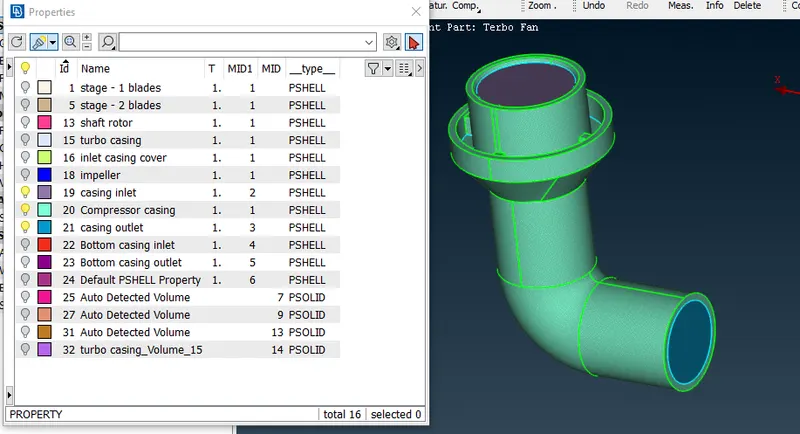
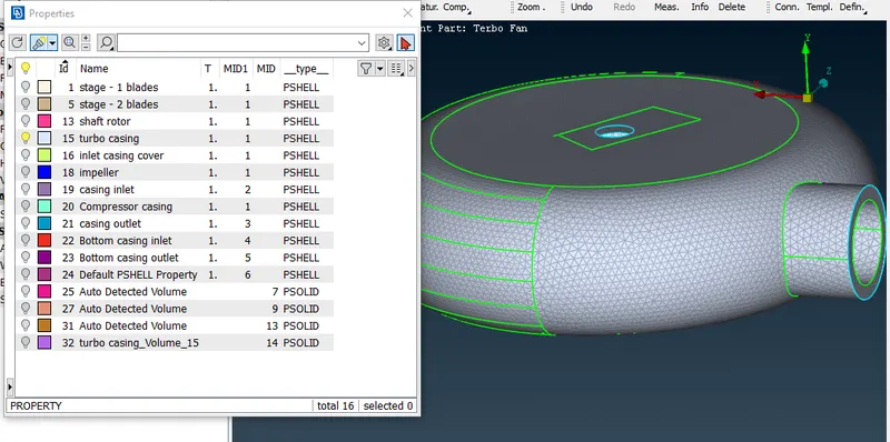
Turbo casing
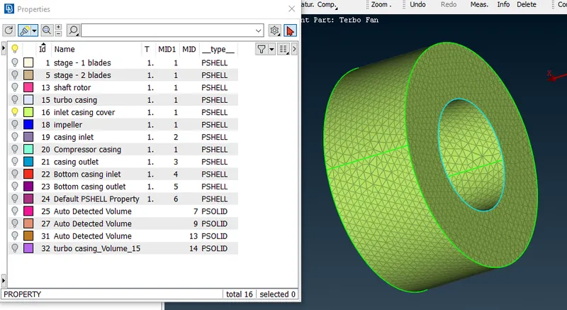
Inlet casing cover
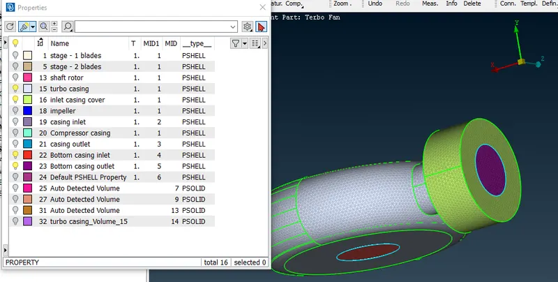
Bottom casing inlet & outlet
Blade stage 1 & 2
Quality criteria:
-----------------
min lengt: 0.5mm
max length: 2mm
blades:
Mesh Length:
perameters: 1mm
macros: 1mm
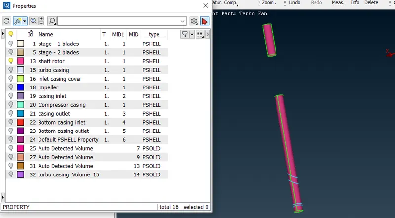
Shaft rotor:
Mesh Length:
perameters: 1mm
macros: 1mm
blade 1
blade 2
Shaft rotor meshing
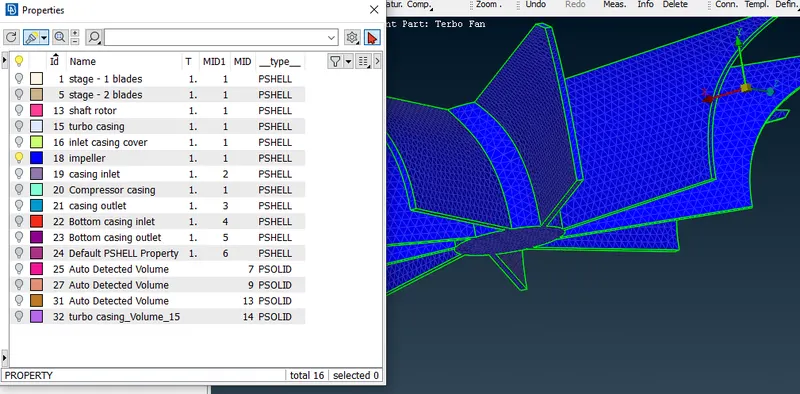
impeller
Quality criteria:
-----------------
min lengt: 1mm
max length: 3mm
Mesh parameters:
target length: 2mm
min length: 2mm
max length: 2mm
Transition elements:
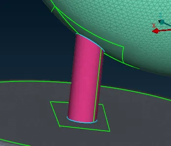
- Give a random cut in the surface to reconstruct the transition phase to seperate by using parametric cut.
Overall mesh:
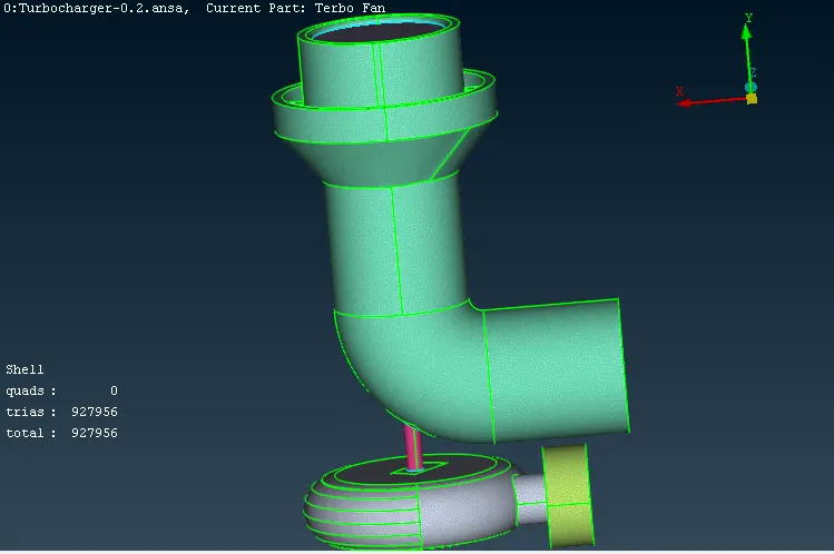
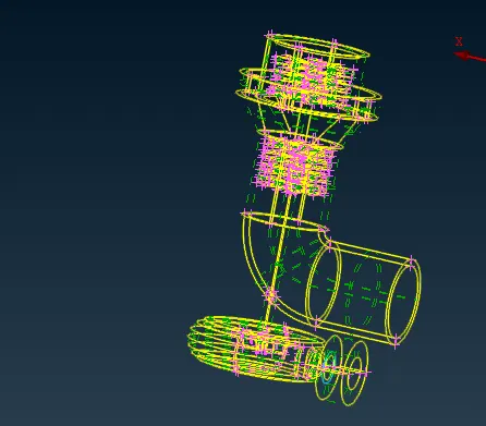
wireframe model:
Results:
Volumetric mesh
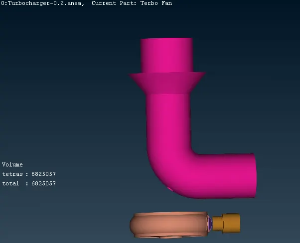
Cross sectional view:
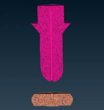
Blades view:

Impeller sectional view
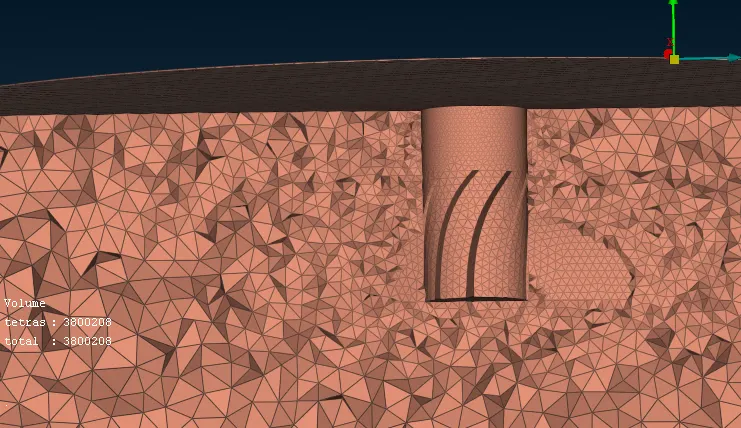
Overall Results:
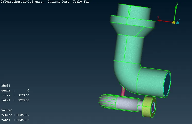
Conclusion:
- Geometric errors are checked and cleared with the appropriate volumes
- PID created and assigned with the respective models
- In the volume options select the define to autodetect the volume check the required volume and not required It is essential to mesh the unmeshed surface
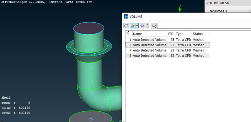
For this project, mesh can be chanaged from undefined to Tetra CFD and remesh the selected items.