Week 3 Challenge : CFD meshing on Turbocharger
Aim: A CFD Meshing On Turbocharger using Ansa.
Objective:
- Perform Surface meshing and Volumetric mesh for the required volume.
Given Data
- Blade Stage_ 1 = 1 mm
- Blade Stage_ 2 = 1 mm
- Impeller = 2mm
- Shaft Rotor =1mm
- Turbo Casing = 5mm
- Compressor Casing = 5mm
- Inlet Casing Cover = 5mm
Turbocharger casing
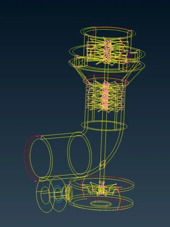
- Wireframe model of turbocharger.
- Shadow mode of turbocharger, having overlap surface on it and many single cones present in model.
- Staring the operation using topo cleanear by doing geometricy check of fluid single and triple cone in the geomerty.
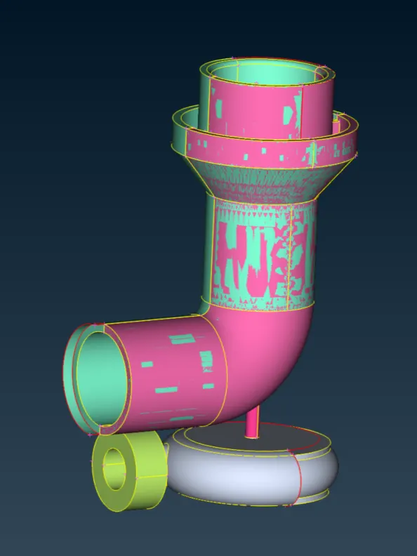
- Staring the operation using topo cleanear by doing geometricy check of fluid single and triple cone in the geomerty.
- Shaft with mixed surface.
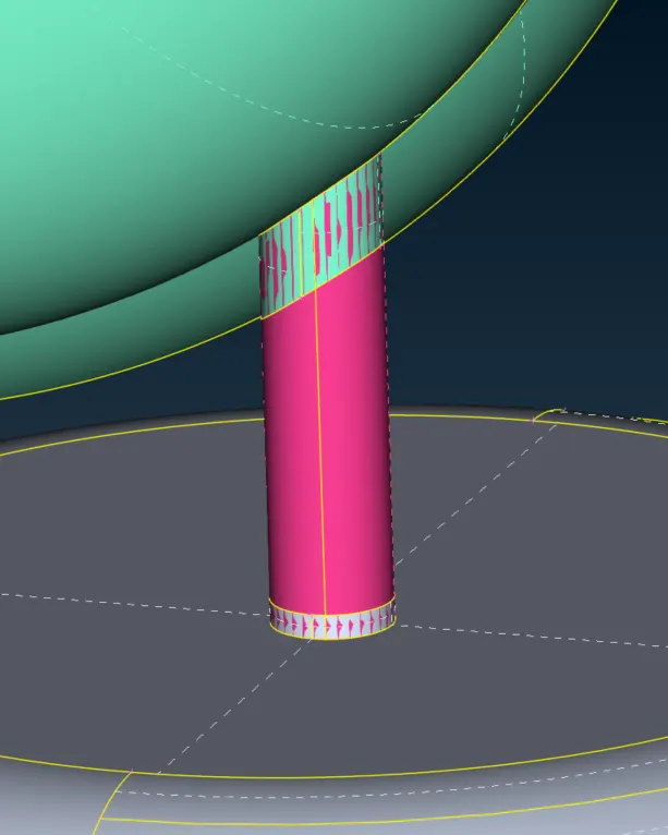
- Before deleting the overlap surface. As we can see the PID color of the model has been changed.
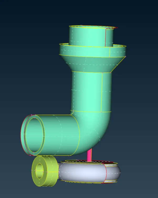
- After Deleting the overlap surface of the shaft.
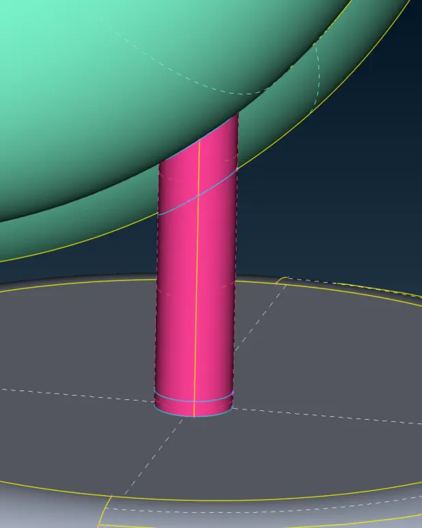
On single cone error making a new surface in the model and deleting the access surface.
- The red color line is an access surface in the turbocharger.
- Using intersection option we had deleded the overlap surface. the separated entity if formed when using intersect and can be deleted easly.
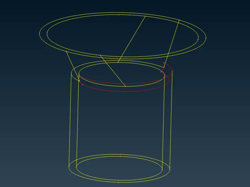
- Using intersection option we had deleded the overlap surface. the separated entity if formed when using intersect and can be deleted easly.
- Patched surface
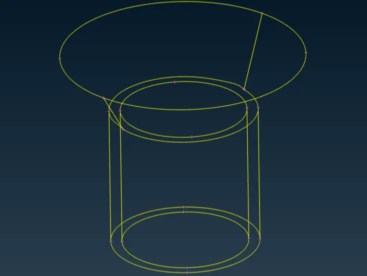
- Turbo casing
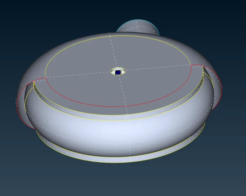
- Patched turbo casing. In this we had projected a hotpoint over the surface and by selecting a single surface to make a curved surface body on casing.
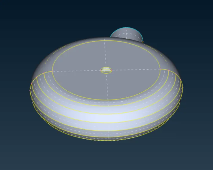
- Body patchup
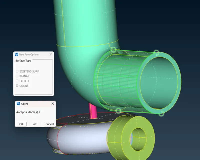
- Upper casing patchup
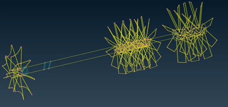
- Wireframe of shaft of turbocharger after deleting the extra surface and projecting the shaft all over the surface.
- Shadow images of shaft
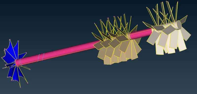
- PID,s Given to turbocharger.
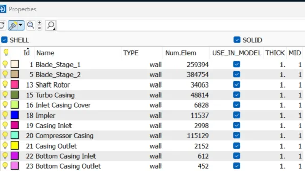
Surface Meshing of a model using Spot mesh.
Every component of the turbocharger has a different type of mesh parameter.
- Surface mesh of Turbo casing, Compressor casing and Inlet casing of turbocharger has mesh length of 5mm.
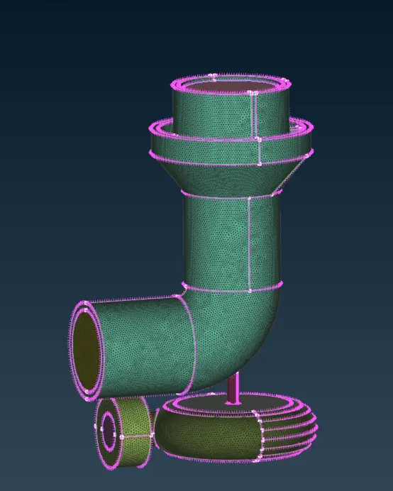
- Shaft rotor having the length of 1mm.
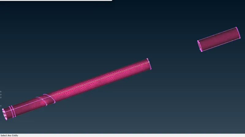
- Blade stage has a mesh length of 1mm.
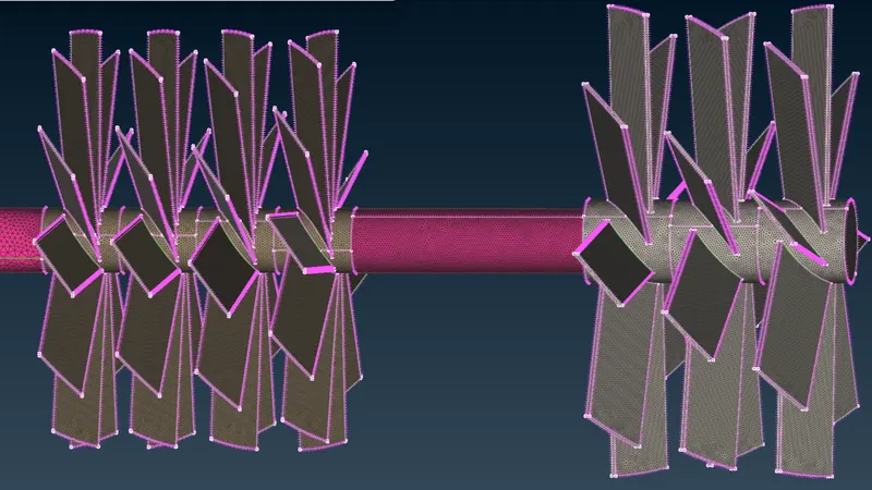
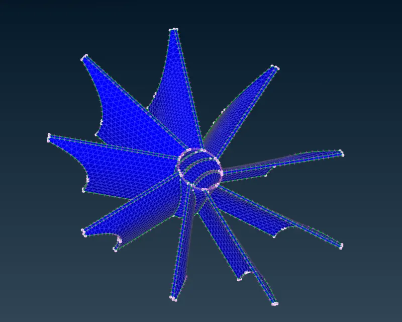
- The Impeller has a mesh length of 2mm.
Volume Meshing Of Turbocharger
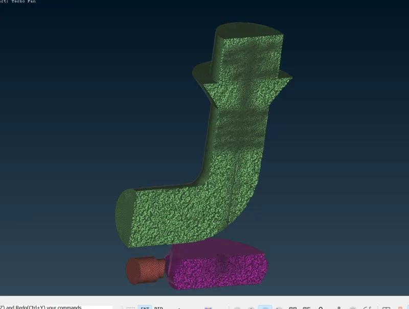
Volume mesh created for the fluid volume region along with a cut section to view the mesh.
In volume meshing choose different and select the whole db in the define window.
We had used unstructured Mesh and selected an Tetra CFD mesh option for mesing the volume mesh.
- List of volume mesh
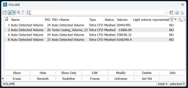
- Volume Meshed
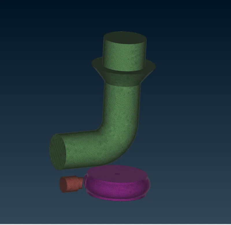
- Half Cut section of turbocharger
Conclusion
- Achieved volumetric mesh of the turbocharger model.
- Volumetric mesh can be achieved only after creating surface mesh successfully, or else the geometry can give fatal errors while volume meshing.
- Unnecessary single and triple cons can be removed and edited using different tools such as cons project, topo, release and fine tools while geometry clean up.
- Different mesh length sizes tend to give errors at the contact regions of 2 different mesh length regions, therefore mesh ranges can be given to avoid erasing of mesh.
- Overlapped surfaces can be deleted using the universal delete option.
- Successful volumetric mesh can be achieved only after correct geometric clean up and surface mesh.