Week 3 Challenge : CFD meshing on Turbocharger
CFD MESHING ON TURBOCHARGER
AIM: Perform surface mesh with the given target lengths as per PIDs for Turbocharger model.
OBJECTIVES:
- Blade stage-1 = 1 mm
- Blade stage-2 = 1 mm
- Impeller = 2 mm
- Shaft rotor = 1 mm
- Turbo casing = 5 mm
- Compressor casing = 5 mm
- Inlet casing cover = 5 mm
Perform Volumetric mesh for the required volumes.
INTRODUCTION:
A turbocharger is a device fitted to a vehicle’s engine that is designed to improve overall efficiency and increase performance. For this reason, many automakers choose to turbocharge their vehicles. A turbocharger, formerly a turbo-supercharger and colloquially known as a turbo, is a turbine-driven forced induction device that increases the power output of an Internal combustion engine by forcing additional compressed air into the combustion chamber.
This improvement over the power output of a naturally aspirated engine is because the compressor can force more air and proportionally more fuel into the combustion chamber than atmospheric pressure alone.
Advantages of Turbocharger
The hot and expanding gases exiting the engine drive a turbocharger so that the engine’s net power is not lost.
Turbocharged engines are also not affected in the same way as naturally aspirated engines when operating at higher altitudes. The higher a naturally aspirated engine climbs, the more difficult it becomes to get oxygen due to the thinning atmosphere.
A turbocharger gets around this problem by forcing oxygen into the engine’s combustion chamber, sometimes at twice the pressure of the atmosphere.
Steps involved for the meshing of Turbocharger:
Import Geometry --- Clean-up the TOPO --- Fill the patches/Holes --- Name PIDs --- Mesh the model (Classic mesh) --- Allow Volumetric mesh --- end.
PROCEDURE/STEPS TO MESHING THE MODEL:
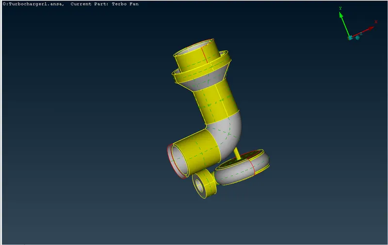
Import the Geometry Form web/file. Apply PID mode to model to specify the color for each part of turbocharger. During this mode changing process we get the highlighted/overlapped surfaces by glitch/random color.
Imported Model:
Geometry model with PID mode:
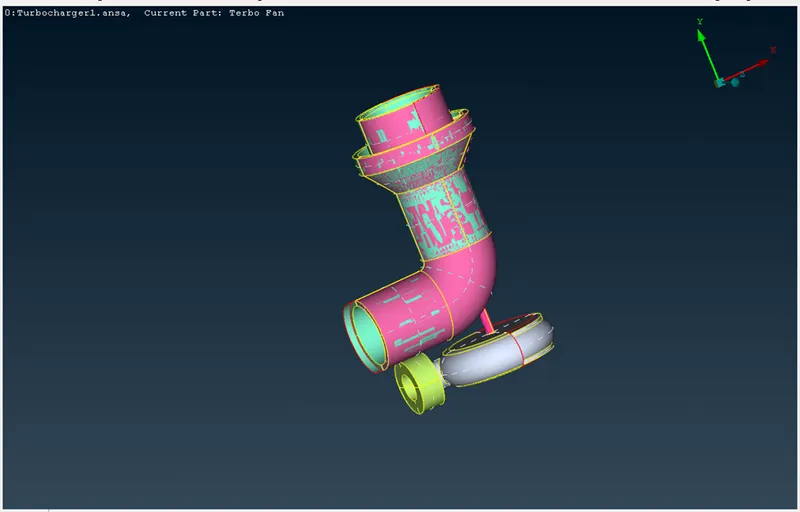
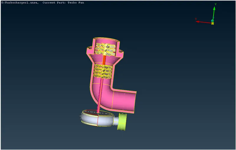
Before going to TOPO deck, we have remove/delete the overlapped surfaces by using NOT function key. The overlapped surfaces are shown below in image. There we can see that the overlapped surfaces are almost occurred on compressor casing.
Some Overlapped parts on model:
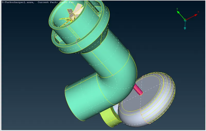
After deleting the overlapped surfaces, we get the turbocharger model as shown in below.
To check the Single cons appearance in model we have to go to check --- geometry --- enable single cons and execute it, then we can see the below image. We have to eliminate the single cons with suitable key points (Project – to create small double cons, Fill hole – to fill the patch/hole on body, CONS/FITTED – to create the cons for small curved con, for turbo model.)
After eliminating the single cons, we have rechecked the geometry. Then the below image is observed.
The below shown errors or negligible by triple cons:
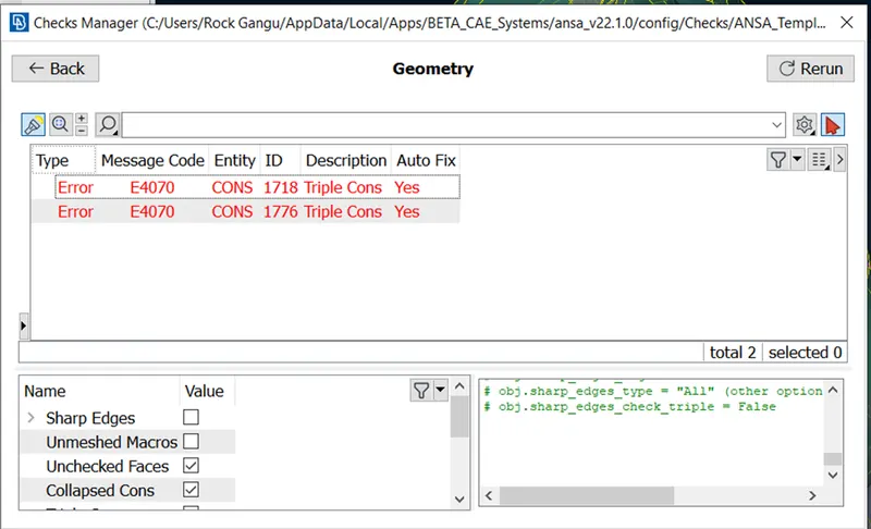
The Internal parts of Turbocharger:
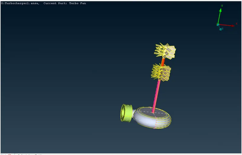
Now to perform the mesh on model the model should have to closed portion on body.
So, we need to close the open holes to perform the mesh in good manner and at that time we get the triple cons those are negligible (During surface creation three surfaces will be formed to close the hole on model), So the below shown triple cons are negligible.
Turbocharger model negligible triple cons:
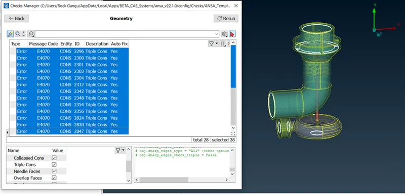
Now the TOPO/extra cons are cleared and has the closed faces condition. Then we have to move towards PID allocation to the each part of model. The PID manager already allocated the parts of the Turbocharger with its own name. So, we have to change the PID names as per requirement and for some region of surface we need to create the PID other than default PIDs.
The below image shows the allocation of parts of Turbocharger.
Turbocharger with PID allocation:
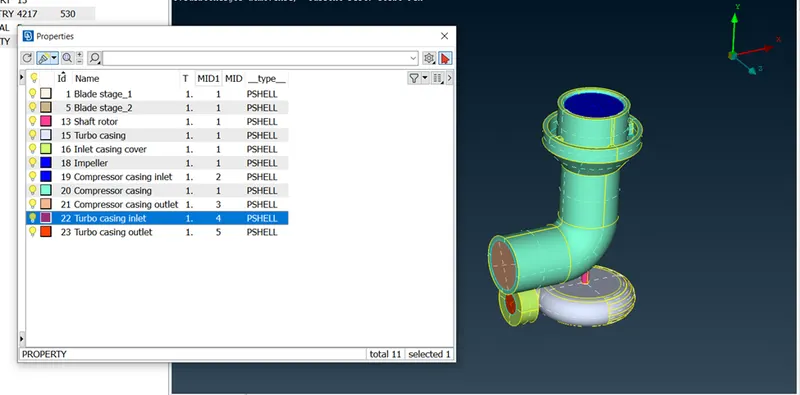
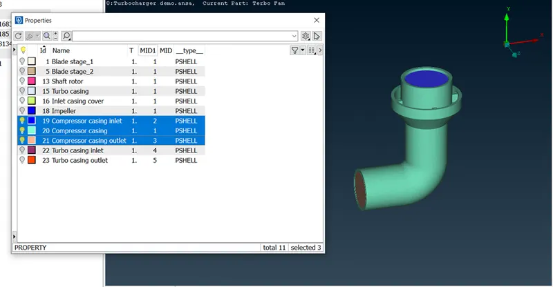
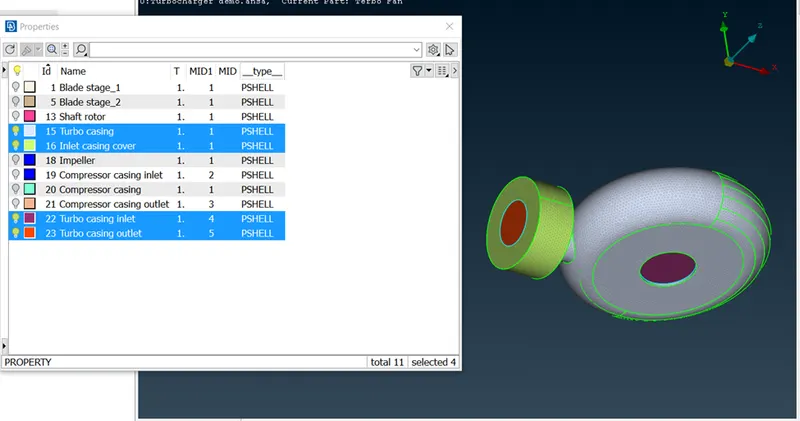
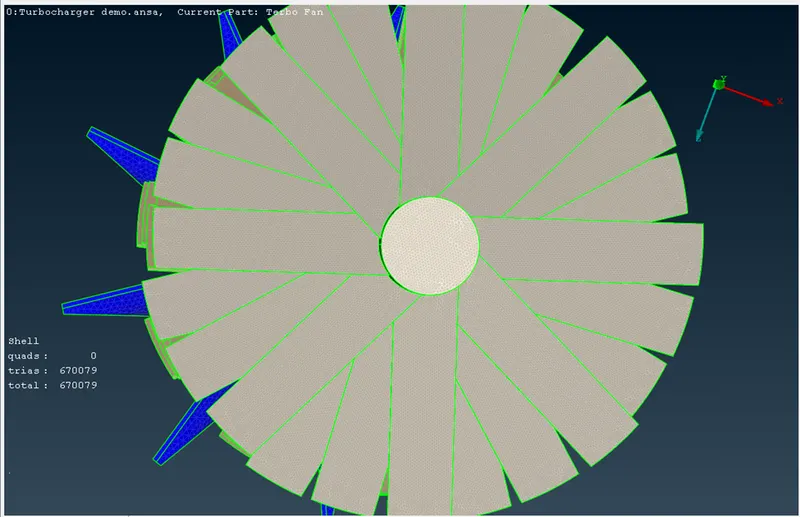
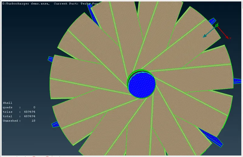
After allocation of PIDs to each part, move to mesh section. We have to mesh the model by classic mesh. In order to avoid the glitch of mesh we need to apply the mesh for separate parts of model. The below images show the meshing of Turbocharger parts. Before applying the mesh on model we have set the target length of mesh in mesh section, Quality criteria of Min. length and Max. length of mesh. And we need to give the Length with perimeter and macros type mesh.
The mesh size for each part is shown below,
|
SI. NO |
Part Name |
Mesh size/length in mm |
|
1 |
Blade stage_1 |
1 |
|
2 |
Blade stage_2 |
1 |
|
3 |
Shaft rotor |
1 |
|
4 |
Impeller |
2 |
|
5 |
Turbo casing, Inlet and outlet |
5 |
|
6 |
Compressor casing, inlet and outlet |
5 |
|
7 |
Inlet casing cover |
5 |
Meshing of Compressor casing:
Turbo casing mesh:
Blade stage_1 mesh:
Blade stage_2 mesh:
Rotor shaft mesh:
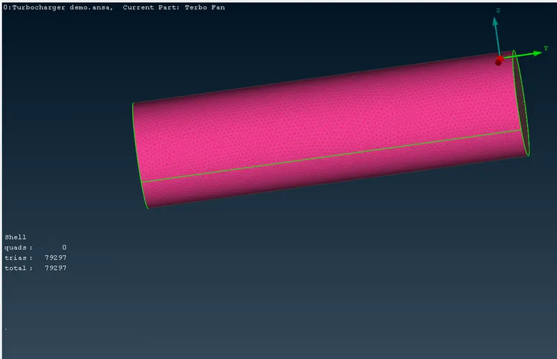
Classic meshed Turbocharger with elements:
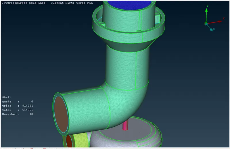
From above meshed model we get some Unmeshed elements. We have to remove to the unmeshed elements.
Remove Unmeshed elements:
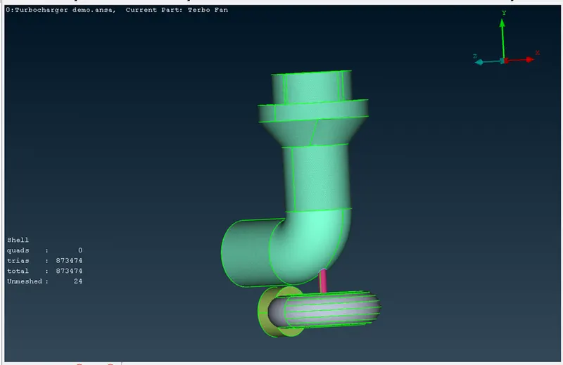
Removed Unmeshed elements:
From removing the unmeshed elements we can see that the meshes are aligned to each mesh in two different parts.
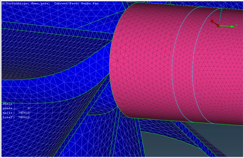
Reduced Unmeshed elements:
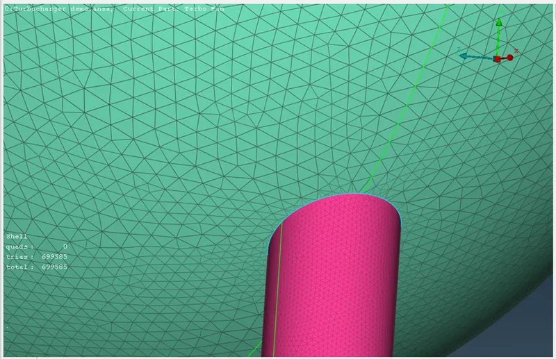
Modified mesh on internal parts:
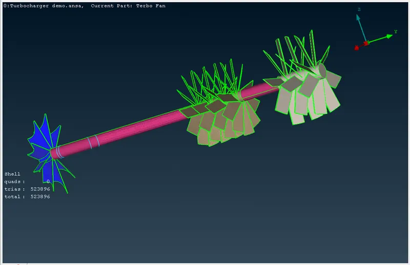
Complete meshed Turbocharger:
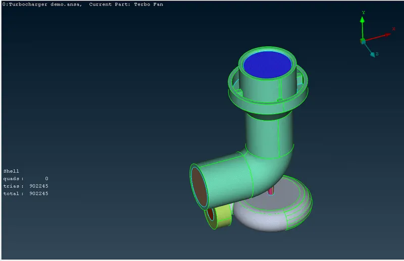
Volumetric Mesh:
To see the Volumetric mesh on turbocharger we have to move to volumetric mesh zone. In that define the meh with whole database. The volumes from the model created automatically and the list of volumes are shown below.
Automatically created volumes of Turbocharger:
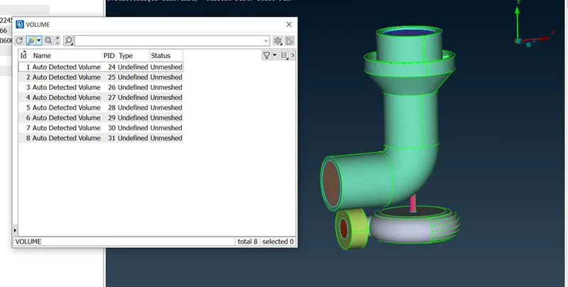
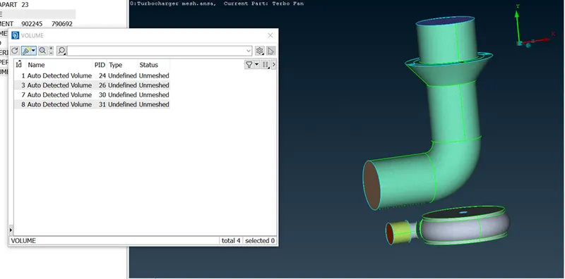
For the Turbocharger model we are meshing only volume of model, which are not occupied by parent Geometry thickness of model. In other words where the fluid will flow in Geometry/model there we mesh or apply the volumetric mesh. So we need to eliminate/delete the solid surfaces of model.
Removing the solid volume:
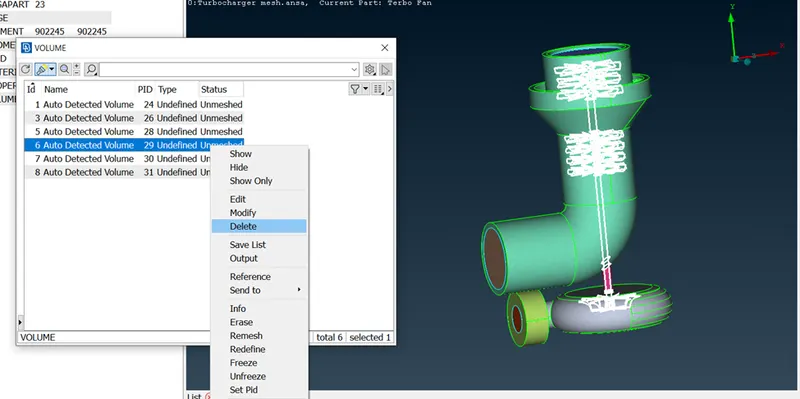
Required volume for volumetric meshing to Turbocharger:
Tetra CFD mesh applied on Turbocharger:
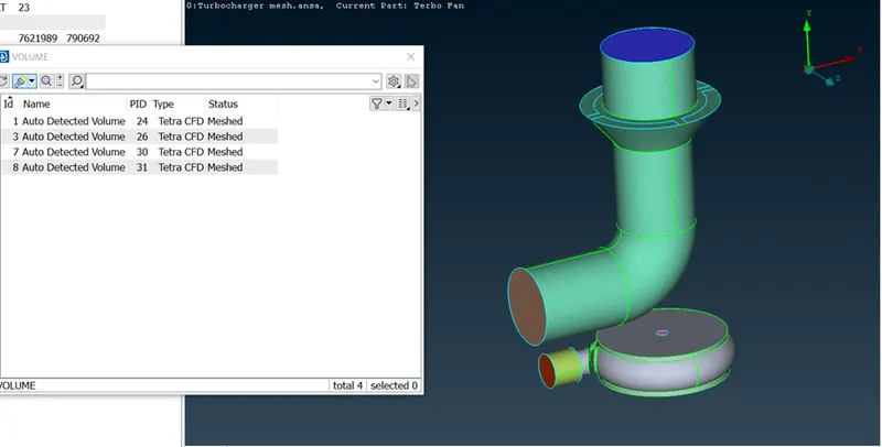
Volumetric mesh applied volume of model:
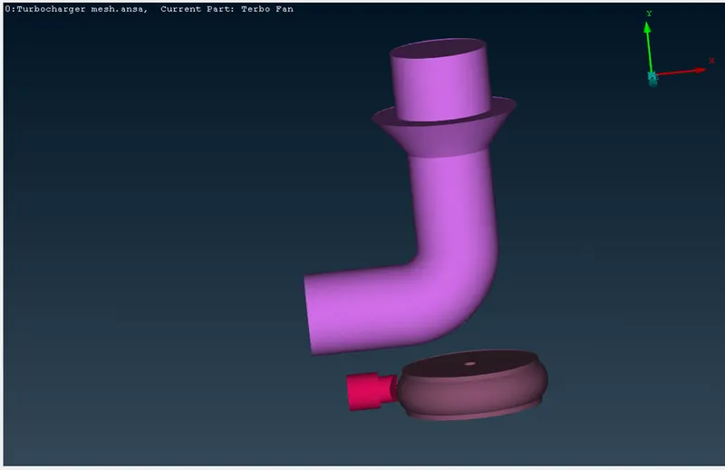
The elements formed on the surface of model:
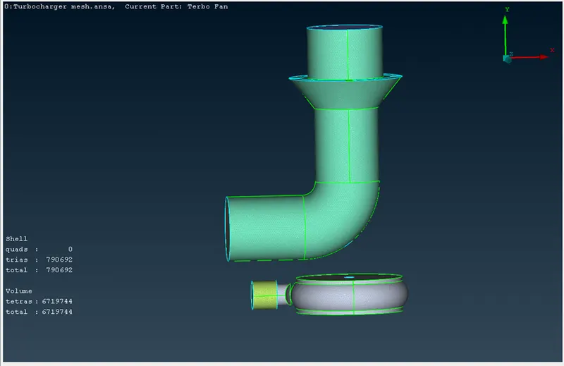
The view of volumetric mesh on Turbocharger:
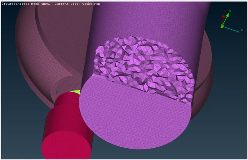
The cut section view of Turbocharger with volumetric mesh:
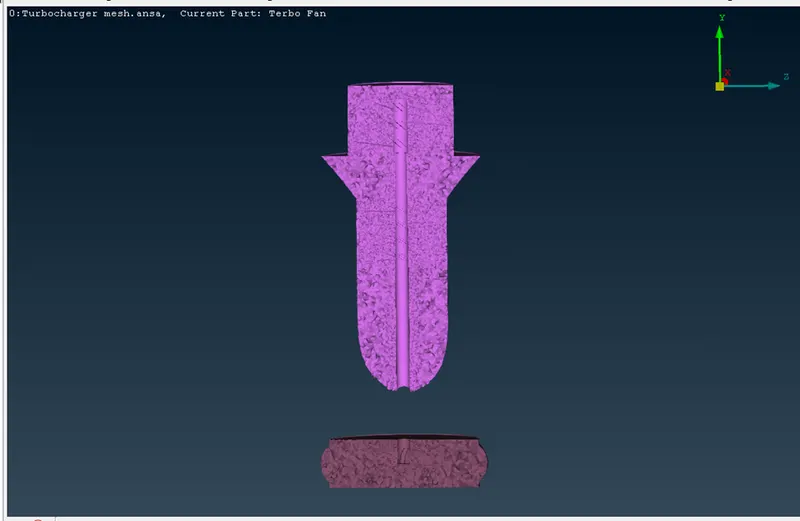
Isometric view of volumetric mesh applied Turbocharger:
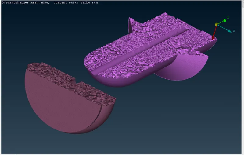
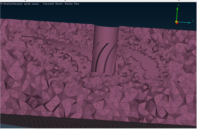
Formation of impeller with volumetric mesh:
Learning Outcomes:
From this challenge we learned about the Topo cleanup for Turbocharger, Classic meshing on Model, PID allocation to model and performing the volumetric mesh on volume of Turbocharger.
Results and Observations:
By applying the classic mesh to Turbocharger, we get the elements of 902245 with Trai type mesh. And from Volumetric mesh we get the elements of 6719744.
During classic mesh application we observed that the formation of mesh between the impeller and shaft rotor, compressor casing and shaft rotor, and Turbo casing and shaft rotor are seen in glitch form, to avoid them we used the project option to collapse the negligible single con with shaft rotor surface. Then we get triple con at single con place. To avoid the glitch mesh applied the macros mesh as range 1-2 for Impeller and shaft rotor. And we gave the macros range from 1-5 for turbo casing and compressor with shaft rotor.
We observe the volumetric mesh applied on volume of Turbocharger. We can that the volumetric mesh formation on each volume part of turbocharger with tetra CFD type mesh.
From images we can see that at outer volume surface the mesh size is larger. As we move to see towards the shaft rotor the formation of volumetric mesh decreases the size mesh with small piece of particle/element. And we can see that the volumetric mesh is not formed in place of shat rotor, blade stages and impeller, there only we can see the classic mesh.
Conclusion:
As per above results and observations we conclude that the volumetric mesh is seen better than the classic mesh and we can find out the elements of mesh volumetric mesh. The Formation of mesh on Turbocharger with classic mesh and volumetric mesh is completed without any error in the dialogue box or check error section.