Week 3 Challenge : CFD meshing on Turbocharger
AIM:
For the given model, check for the geometrical errors to make appropriate volumes. Create and assign PIDs. Perform surface mesh with the given target lengths as per PIDs.
- Blade stage-1 = 1 mm
- Blade stage-2 = 1 mm
- Impeller = 2 mm
- Shaft rotor = 1 mm
- Turbo casing = 5 mm
- Compressor casing = 5 mm
- Inlet casing cover = 5 mm
Perform Volumetric mesh for the required volumes.
OBJECTIVE:
- Check for the geometrical errors to make appropriate volumes.
- Create and assign PIDs.
- Perform surface mesh with the given target lengths as per PIDs.
- Perform Volumetric mesh for the required volumes
PROCEDURE:
TOPOLOGICAL CLEANUP & PID ASSIGNING
- Under checks- geometrical checks- template-ANSA[AUTO GENERATED TEMPLATE]-visible
- Found out several locations of single cons and filled with appropriate fills.
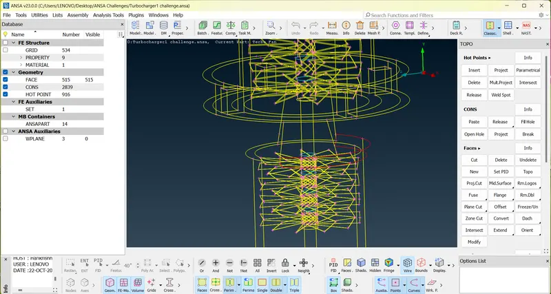
- In several locations during topo cleanup, intersect and faces and delete where used to convert single cons.
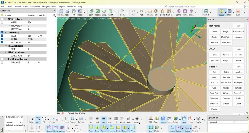
- In some locations single cons were converted to triple cons by using TOPO.
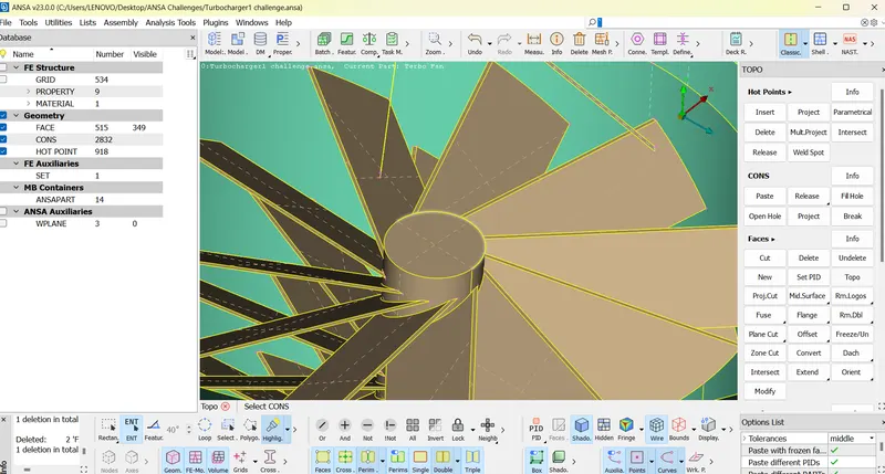
- In curved locations, multiple hotpoints was created using parameteric option and connected by coons in faces.
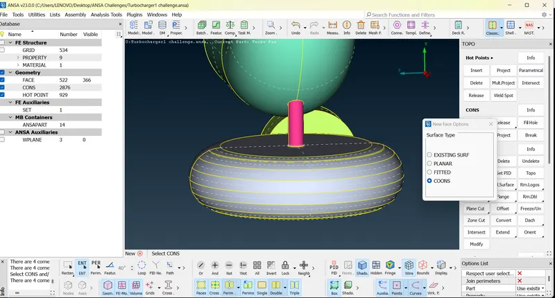
- Single Cons to triple cons using TOPO.
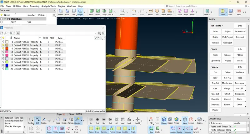
- After topocleanup PIDs were assigned.
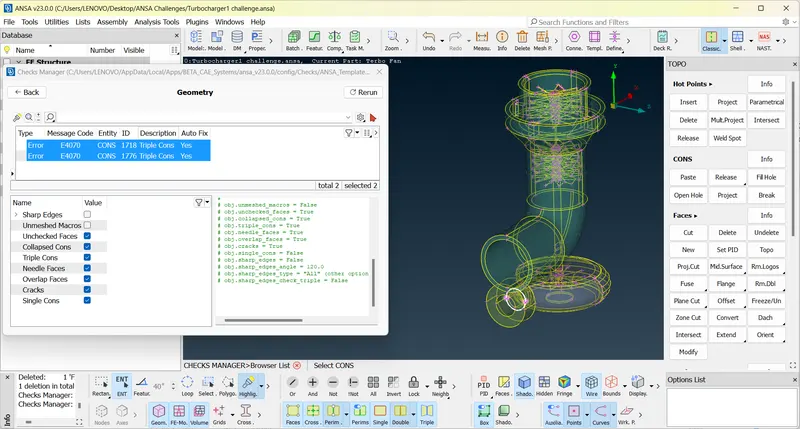
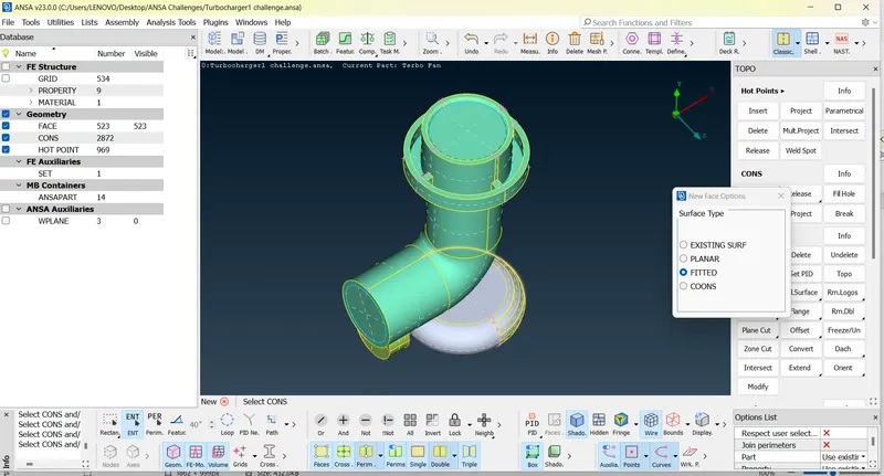
- It is necessary to fill all gaps for volumetric meshing. So fills where done to avoid leakage in CFD analysis.
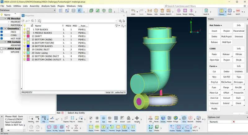
- All PID’s name is given.
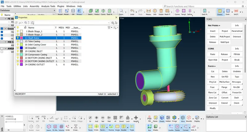
SURFACE MESHING
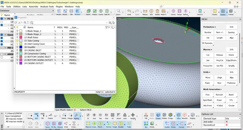
- 5mm meshing carried out for turbo casing, inlet cover casing and compressor casing.
5MM TARGET LENGTH
- Select Mesh parameters and set target length as 5mm and Select Quality Parameter and set minimum length as 3mm and maximum length as 7mm.
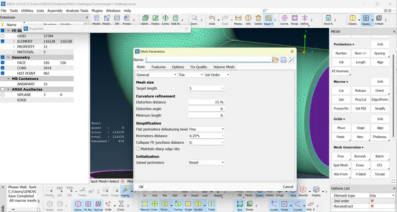
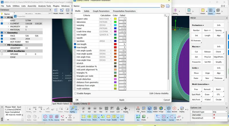
- Select Mesh deck and and select mesh parameters by selecting CONS of each PIDs and set length as 5mm and select macros and set as 5mm.
- Now select spot mesh and select face and middle click on mouse to see the meshes.
- Continue for each PID’s by NOT, Neighbour, All, AND, OR options in visibility tab.
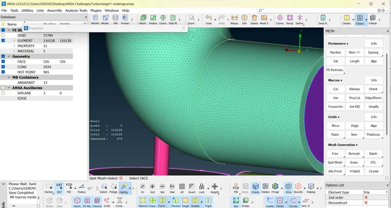
- 2mm meshing carried out for impeller.
2MM TARGET LENGTH
- Select Mesh parameters and set target length as 2mm and Select Quality Parameter and set minimum length as 1mm and maximum length as 3mm.
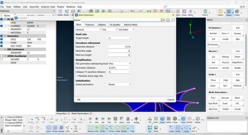
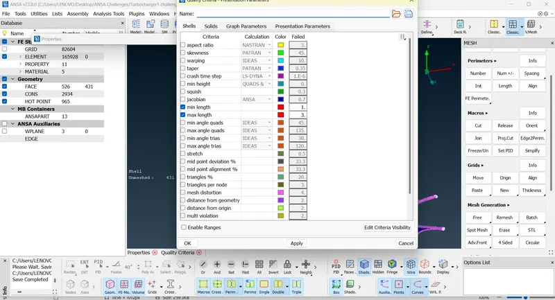
- Select Mesh deck and and select mesh parameters by selecting CONS of each PIDs and set length as 2mm and select macros and set as 2mm.
- Now select spot mesh and select face and middle click on mouse to see the meshes.
- Continue for each PID’s by NOT, Neighbour, All, AND, OR options in visibility tab.
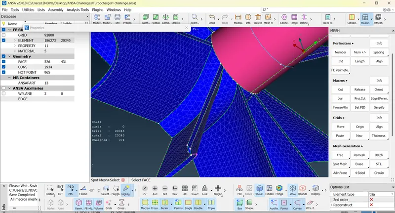
- 1mm meshing carried out for blade stage 1, blade stage 2 and shaft rotor.
1MM TARGET LENGTH
- Select Mesh parameters and set target length as 1mm and Select Quality Parameter and set minimum length as 0.5mm and maximum length as 2mm.
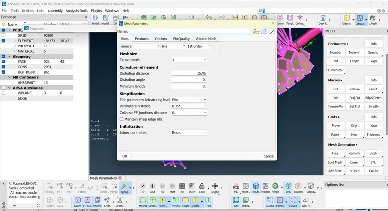
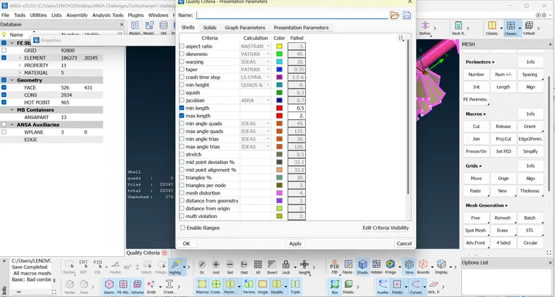
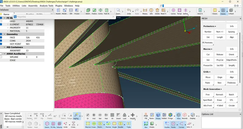
- Select Mesh deck and and select mesh parameters by selecting CONS of each PIDs and set length as 1mm and select macros and set as 1mm.
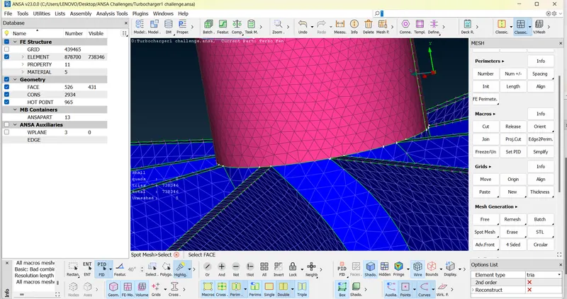
- Now select spot mesh and select face and middle click on mouse to see the meshes.
- Continue for each PID’s by NOT, Neighbour, All, AND, OR options in visibility tab.
VOLUMETRIC MESHING
- Click on V.Mesh and define volumes.It was noted that 9 volumes is autogenerated.
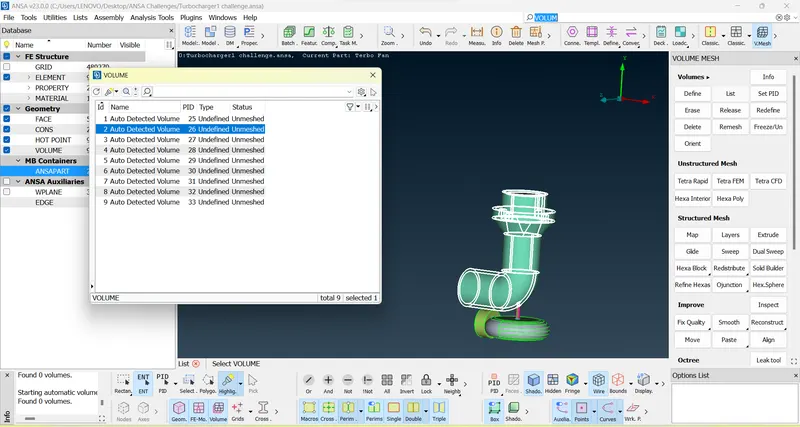
- Out of all volumes, 4 volumes where found to be perfect suited for CFD analysis.
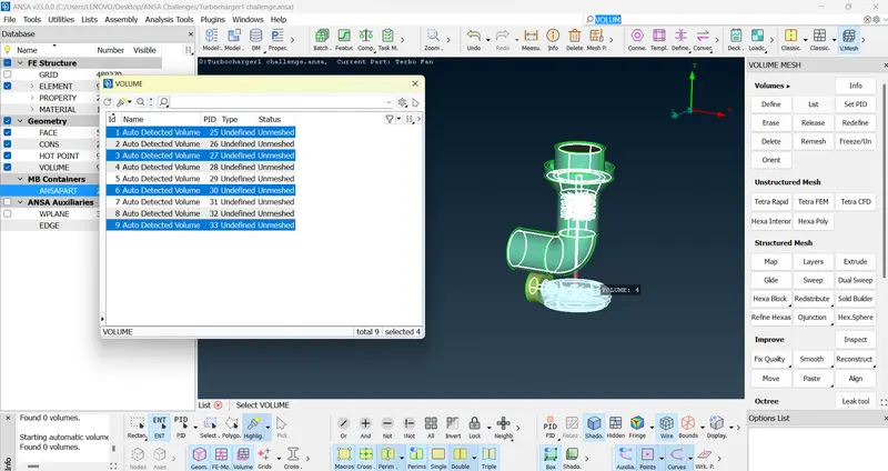
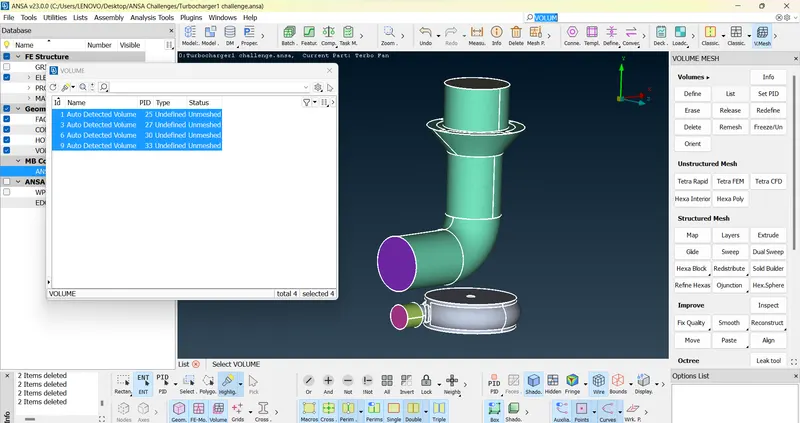
- Now each Volume is assigned PID and TETRA CFD meshing is done. But it was found that a leak is observed with unmeshed 1 volume. THIS WAS AN ERROR.
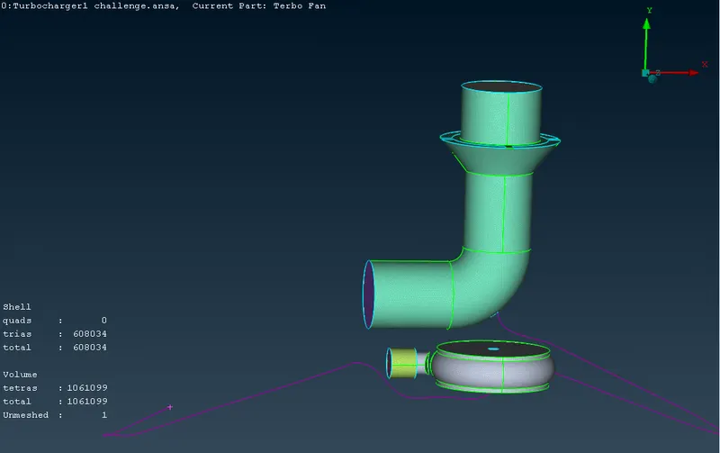
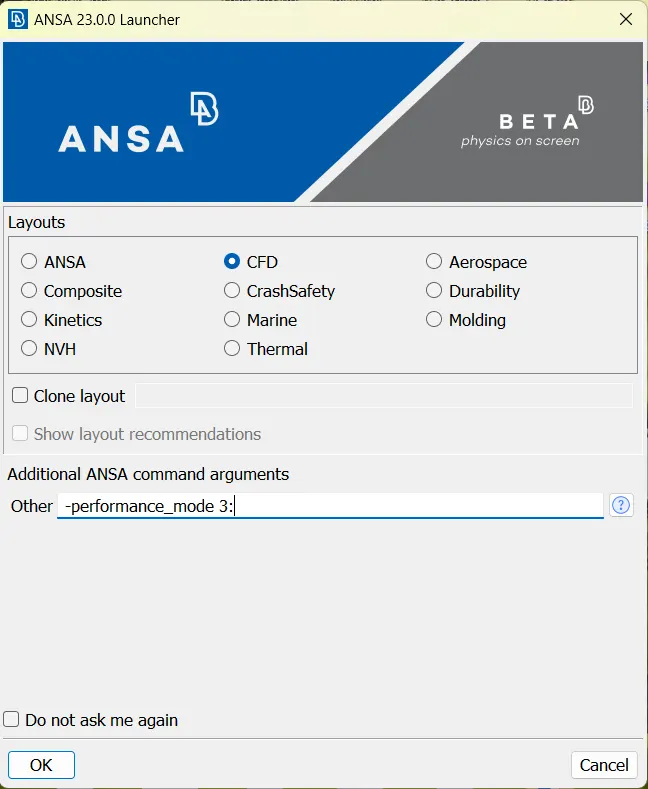
- I restarted the ANSA by selecting ANSA CFD And repeated the same process.This time I was able to mesh using Tetra CFD on all four volumes.
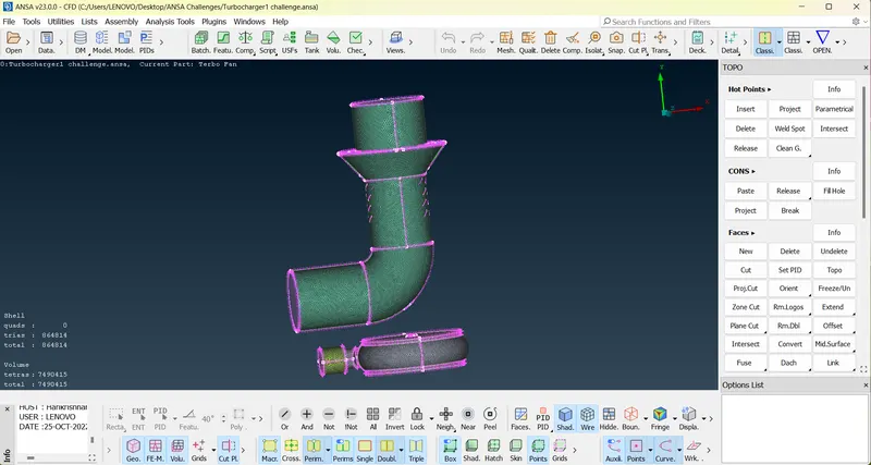
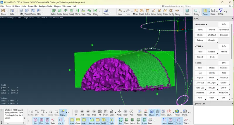
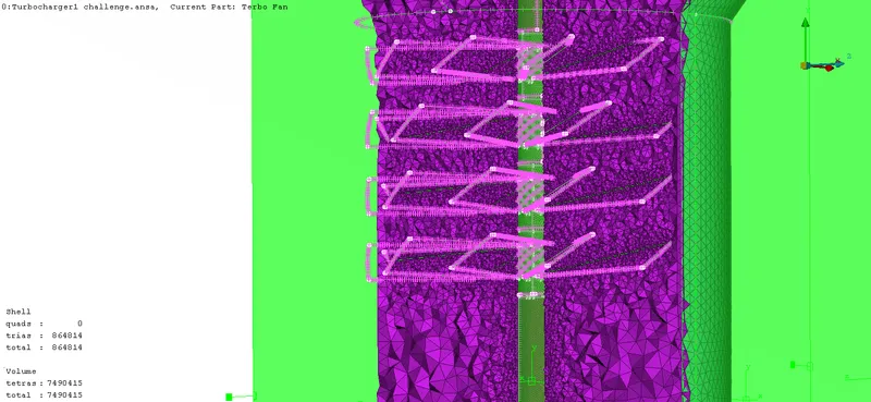
- Cut section of a part of Volumetric meshed is shown below.
LEARNING OUTCOME:
- Lifelong Learning
- Modern Tool Usage
- Communication
RESULT:
- Checked for the geometrical errors and made appropriate volumes.
- Created and assigned PIDs to all shells.
- Performed surface mesh with the given target lengths as per PIDs.
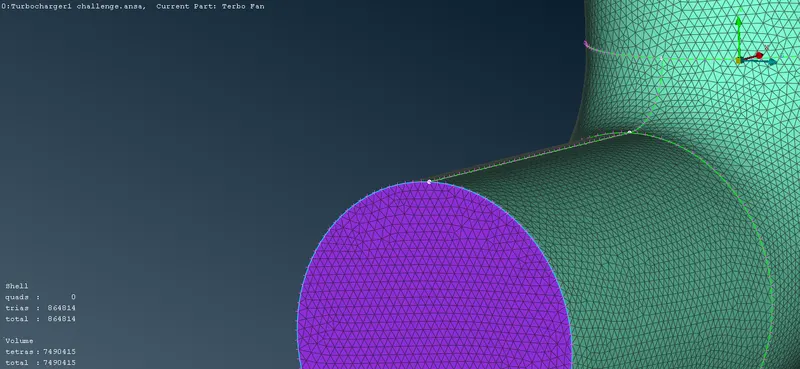
- Performed Volumetric mesh for all the required volumes.
ATTACHMENT: GOOGLE DRIVE LINK OF WORKED MODEL:https://drive.google.com/drive/folders/1EK_tNyiiOEeVVLHOU121pkII0U28dwY3?usp=sharing
CONCLUSION:
Best results were obtained when mesh sizes were smaller, but increase in mesh elements is not appreciable as this may leade to more computation times while making volumetric meshes.