Week 3 Challenge : CFD meshing on Turbocharger
AIM:For the given turbocharger model, we need to do geometry cleanup and perform surface mesh with given target length followed by performing volumetric mesh.
TARGET LENGTH FOR DIFFERENT PID'S
Blade stage-1 = 1 mm
Blade stage-2 = 1 mm
Impeller = 2 mm
Shaft rotor = 1 mm
Turbo casing = 5 mm
Compressor casing = 5 mm
Inlet casing cover = 5 mm
OBJECTIVE: We will perform three process to achieve the aim.
a)Geometrical/Topological cleanup
b)Meshing process
c)Volumetric meshing process for re
PROCEDURE:
GEOMETRICAL CLEANUP
1. First we will enter PID mode from ENT mode to see the overlapped surfaces visible properly.
2. Deleting overlapped surfaces using DELETE option. (we can use PID manager to delete the surfaces at once).
3. Deleting extra surfaces.
4. Creating new faces using following commands
NEW<fitted<selecting cons
Creating hot points at critical voids for getting smooth surfaces. Using commands Fill hole,New,Fitted .
5. Using Intersection<select first face and second face vice versa< select the extra inersecting faces and delete.
6. Deleting overlapped surfaces present in shaft and also deleting the middle joining surfaces to make a shaft rotor a s a single geometry.
7. We also require following command for projecting cons in some cases to select the desired entitiy.
Cons<Project<select the cons to be projected<select the surface in which cons need to be project<left click<Auxillaries<Fine<Click on the cons multiple times to get fine cut.
8. Resolving the single cons errors,triple cons errors (which are not required) using TOPO<topo<box select entire geometry.
9. Closing the geometry using New<faces<coons<selecting the face.
10. Running the geometry checks.
SURFACE MESHING
1. Assigning and creating PID's according to our objective.
right click <new<pshell<name the PID.
right click<apply <assign the PID.
left click<rename the PID accordingly.
delete the unwanted PID region using COMPRESS.
2. Selecting the PID<giving target length& element type as TRIA<giving minimum & maximun length<defining quality criteria<length<perimeter & macros<giving lengths<mesh <spot mesh<visible or select.
3. we will perform meshing with three different target length 1mm (blade stage1,blade stage2,shaft rotor),2mm (impeller),5mm(Compressor and turbo casings as well as inlet and outlet)
4. We will facing issues of deleted mesh area at points where two surfaces are getting connected having diff mesh lengths.resolve it using following command
assign the mesh length and quality criteria which is greater among them i.e(2>1) select 2mm as target length and mesh the pid again which need to be meshed with 2mm and then mesh the pid
having small TL(1mm) using above given commands <macros should be ranging (1-2) and let the permeters lengths be default as 1mm.<perform spot mesh<select<mesh.
5. Draw a cut at the area wher two different mesh length are getting connected using ,Cut<reconstruct<parametric cut< select the region manually by clicking.
6.check if the unmeshed surfaces are zero.
VOLUMETRIC MESHING
1. Volumetric deck<Define<auto select<whole db<left click.
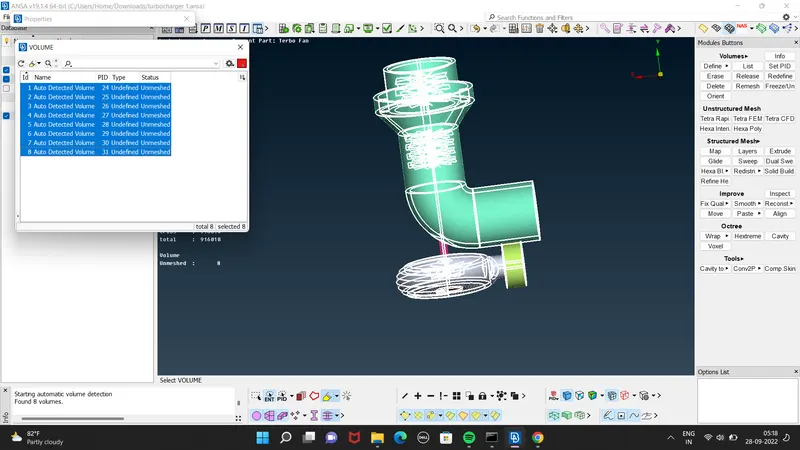
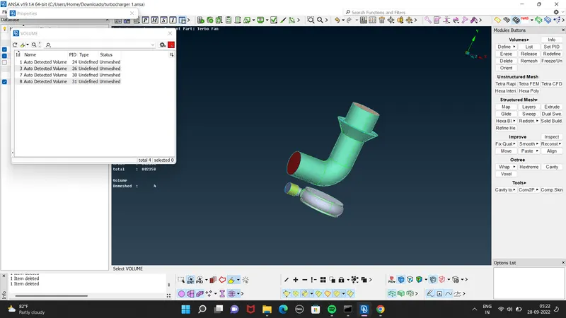
2. We wiil be able to see 8 uunmeshed volumes.As we will performing CFD Tetra mesh we need select the area only where the fluids volume will flow.
3. we will simply delete the unwanted volume using right click.
4.For meshing Right click<remesh<CFD tetra<left click.
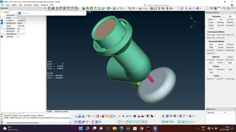
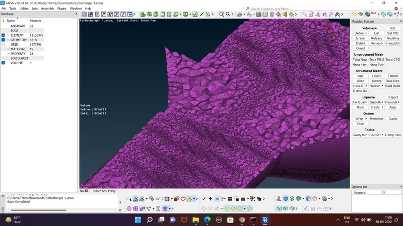
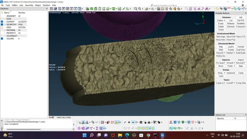
5. Simply mesh all the 4 required volumes.
TOPO CLEANING
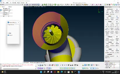
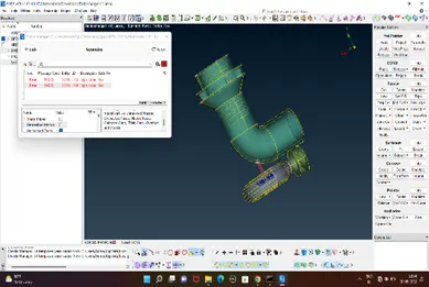
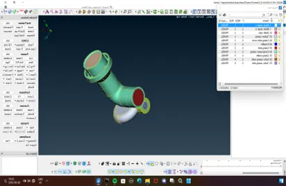
SURFACE MESHING:
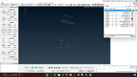
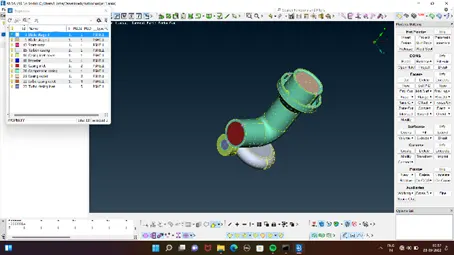
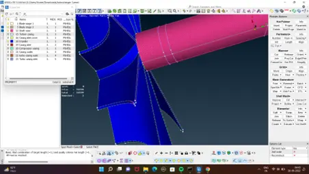
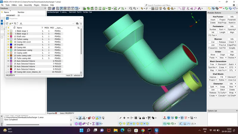
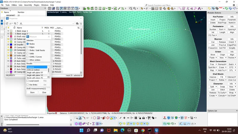
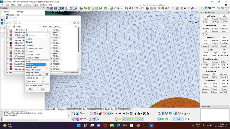
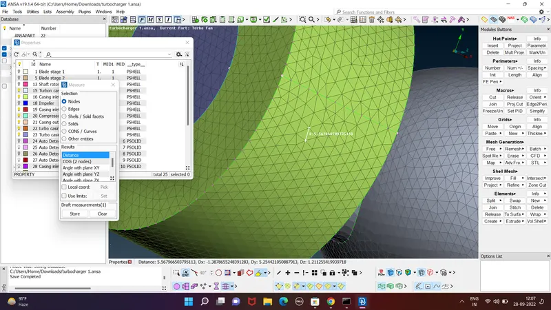
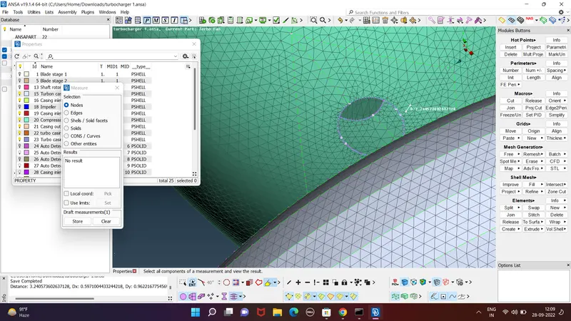
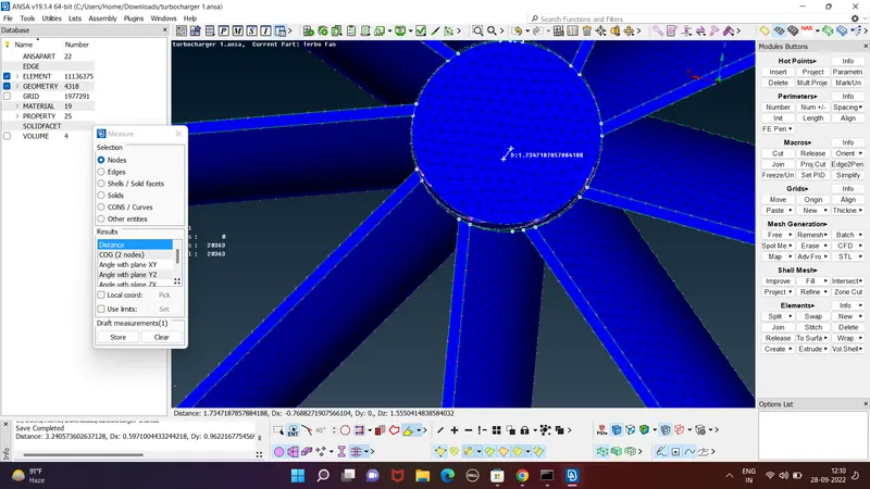
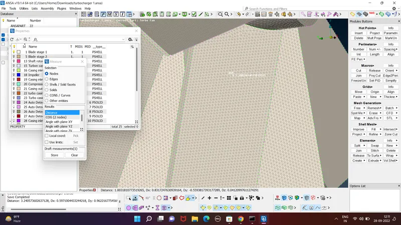
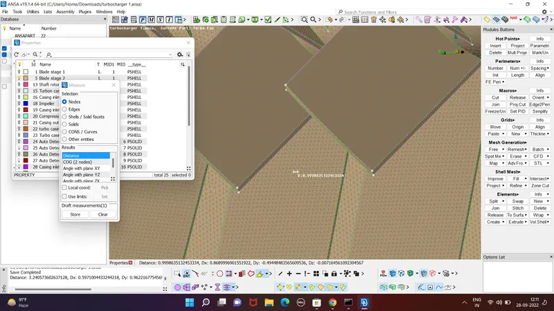

VOLUMETRIC MESHING:
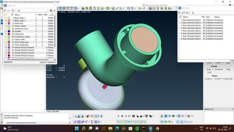
volumes to be meshed
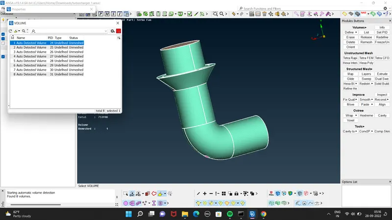
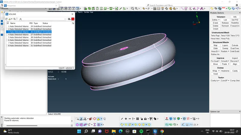
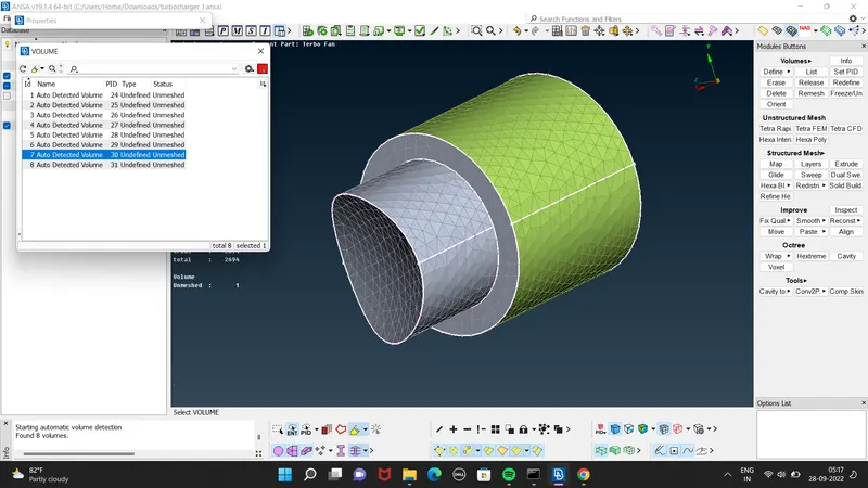
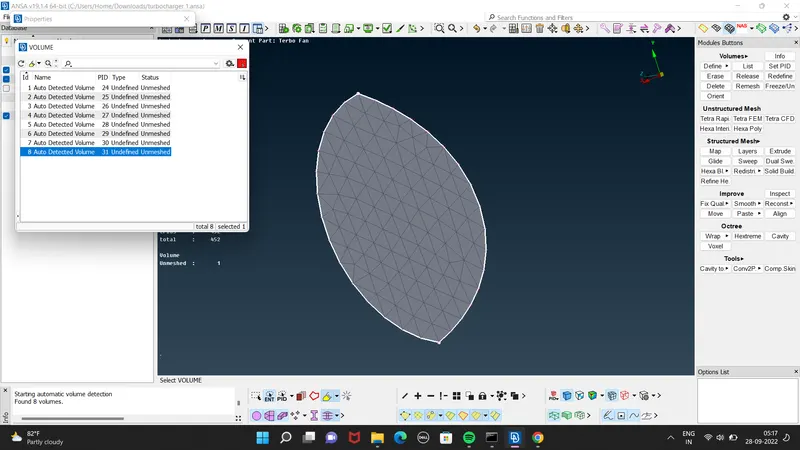
Volumes to be deleted
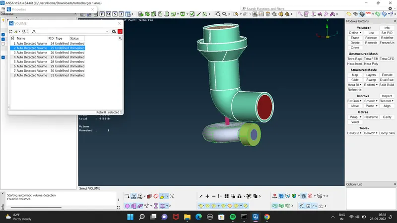
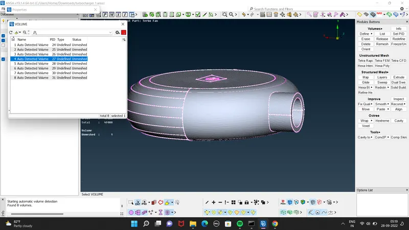
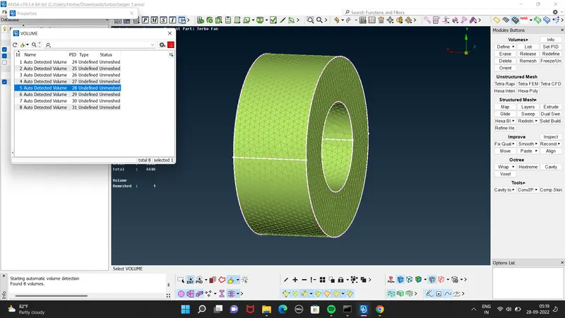
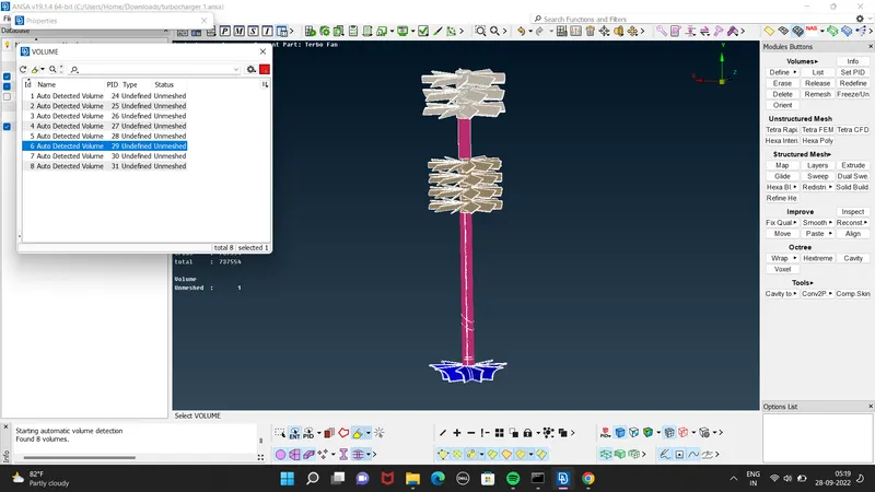
Total volumes
RESULT(MESHED VOLUME)
CONCLUSION:
Learned about some new tools
PROJECT COONS,TOPO,RELEASE CONS,INTERSECT,FINE THE CONS ,DEFINING VOLUMES,SURFACE DELETING METHODS,CREATING SURFACES USING HOTPOINTS,FILL HOLE,LIST TO SEE VOLUMES,
EXECUTE GEOMETRY RUN,SOLVE SINGLE CONS ERRORS,EXAMINE TRIPLE CONS,ISOLATING VOLUMES,ISOLATING SURFACES AND PIDS,APPLYNG SURFACE MESH DIFFERENT TL's,RESOLVING
SURFACE MESHING ERRORS,PERFORMING VOLUMETRIC MESHING USING REMESH
ONE DRIVE LINK