Week 3 Challenge : CFD meshing on Turbocharger
Aim:For the given model, check for the geometrical errors to make appropriate volumes. Create and assign PIDs as shown in the video. Perform surface mesh with the given target lengths as per PIDs.
- Blade stage-1 = 1 mm
- Blade stage-2 = 1 mm
- Impeller = 2 mm
- Shaft rotor = 1 mm
- Turbo casing = 5 mm
- Compressor casing = 5 mm
- Inlet casing cover = 5 mm
Perform Volumetric mesh for the required volumes as shown in the videos.
Write a detailed report on your surface meshing & Volume meshing process.
Procesure:
- Geometry Cleanup:The geometry is imported in ANSA.Perporming geometry cleanup gives shows mny errors such as single cons,triple cons,intrdection errors.
Given Geometry:
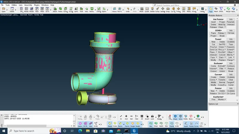
- As shown in geometry,there are are lot of errors shown.we can remove them one by one.To reove overlp surface we select PID region and then select that overlap region and delete using universal delete option.After remiving overlap surface geometry look like this
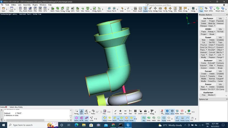
- Next process is removing the single cons by creating the surfaces where required.Using new option creat all the surfaces.
- To remove intersection error select the component which are intersecting in first and second group selection and after that keep the surface which is required and delete the unnecessary surfaces.
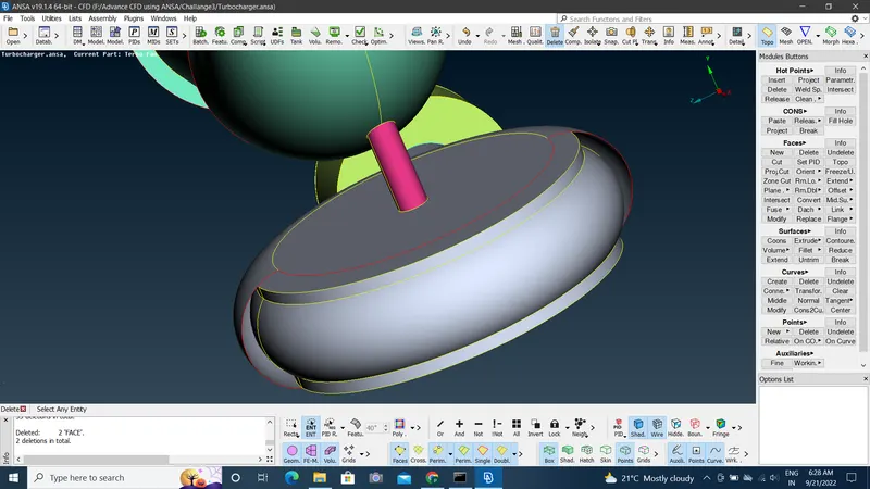
- Now the below part needs to fill the surface.For creating the surfaces we used to project the hot points. Then we use new >Coons option to creat surfaces.
- Before:
- After:
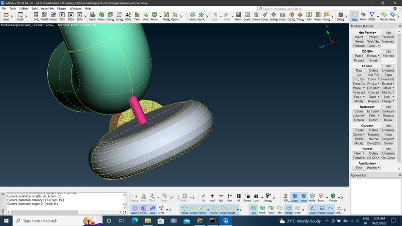
- There are many errors on shaft & Blades.removing the trple cons by remving overlap surfeces.The triple cons is also present on impeller so we use CONS > project option to project cons which is present on shaft to impeller then we delete the surface.
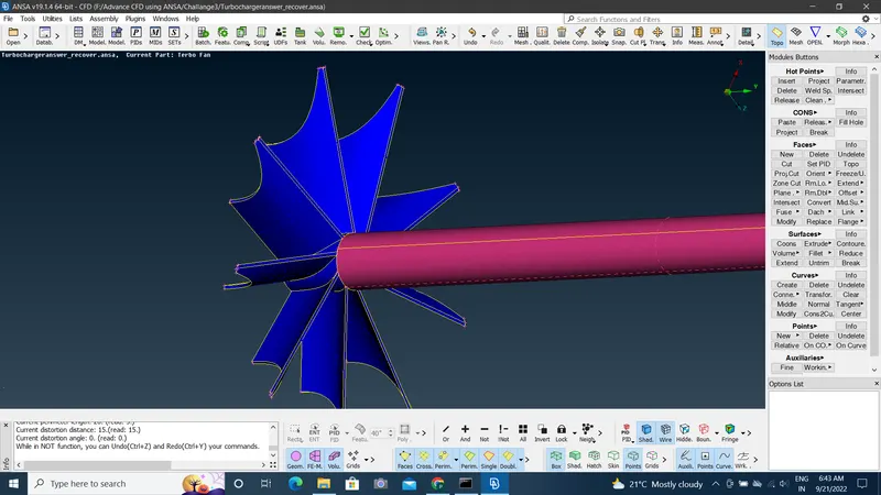
- After removing all the errors we can assign the PIDs.
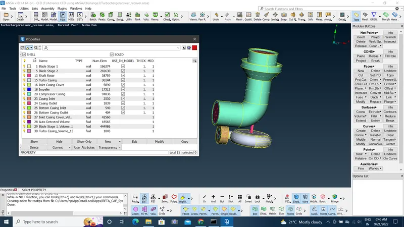
- Surface Meshing :By selecting PIDs one by one and then perforning surface mesh by using the mesh length given for every PIDs.As per given target length and setting quality criteria & mesh length permorm mesh.
- Outer Casing
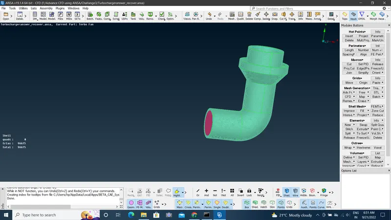
- Turbo Casing
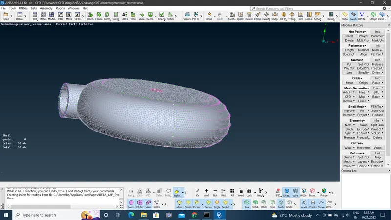
- Inlet Casing Cover:
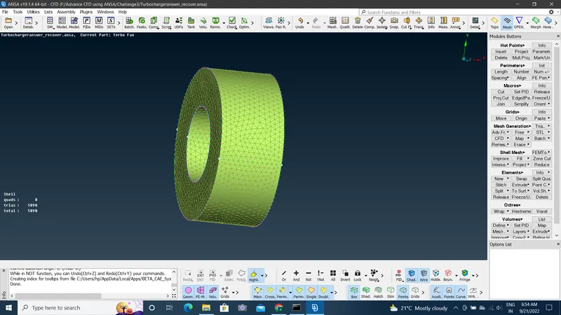
- Casing Inlet
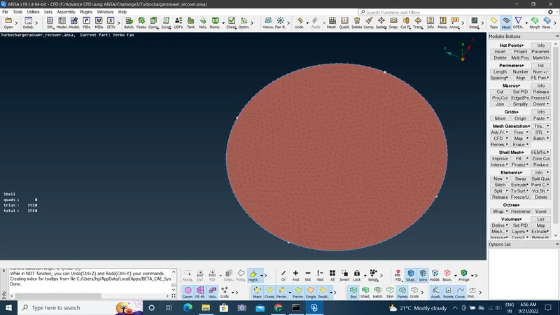
- Casing Outlet
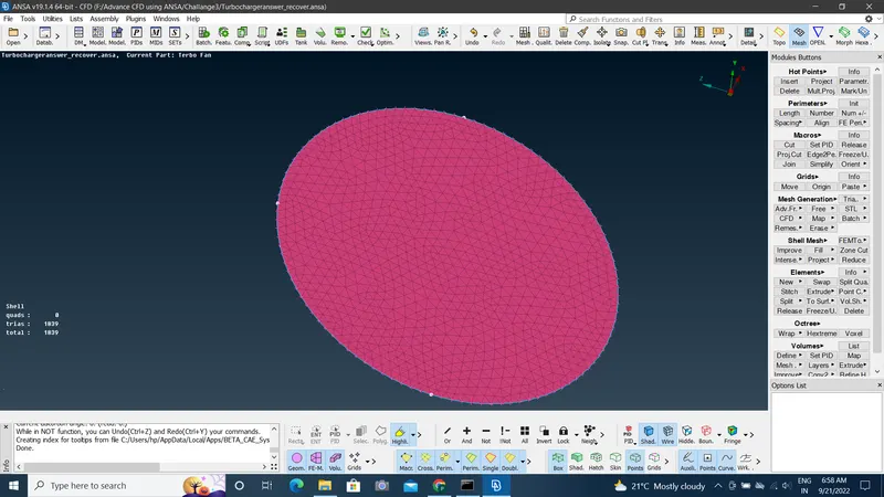
- Impeller Shaft:
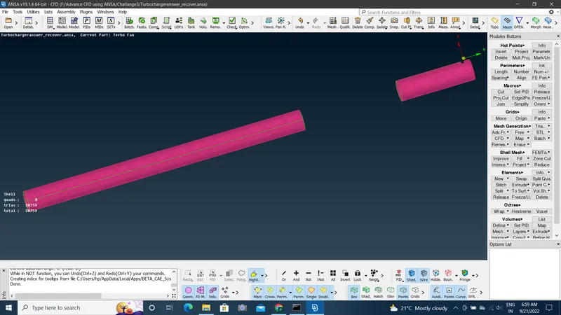
- Blades Stage 1 & 2:
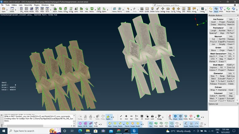
- Impeller:
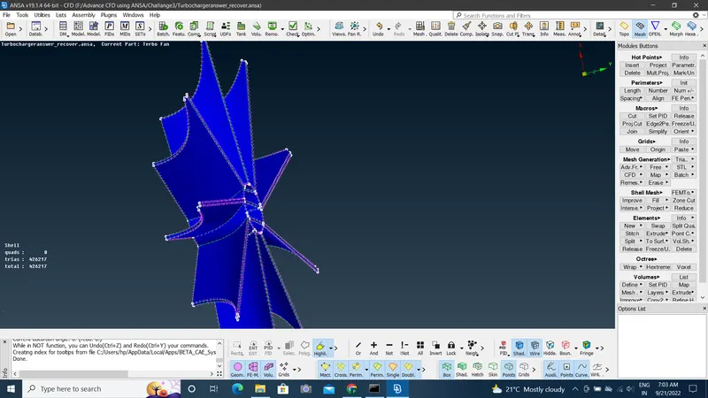
- Bottom Casing Inlet:
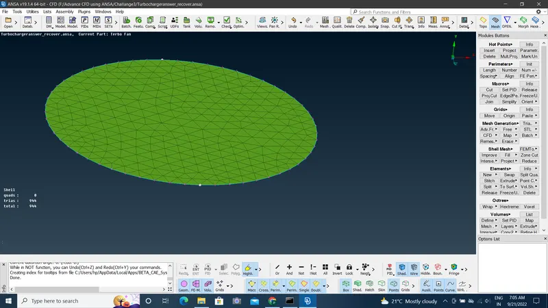
- Bottom Casing Outlet
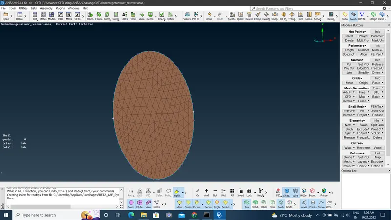
- After Surface meshing geometry looks like:
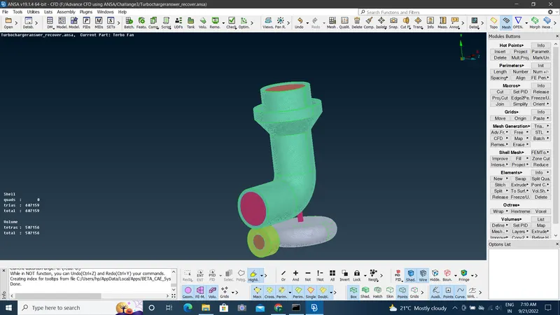
- Performing Volume Meshing:
- In volume mesing selecting define option >Whole db>ok. We get the various volumes. unwanted volumes are deleted. Then we use Remesh Option for meshing unmeshed parts.
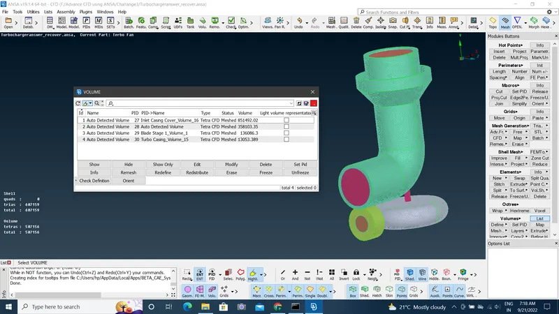
- Result:
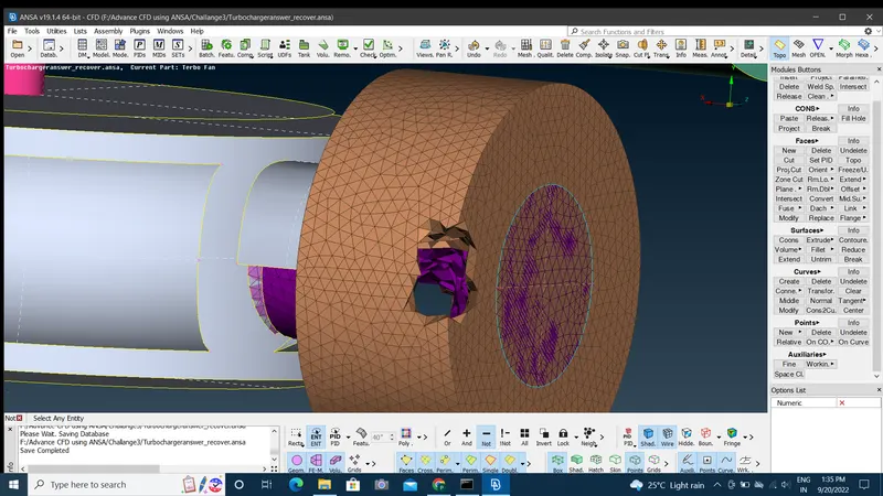
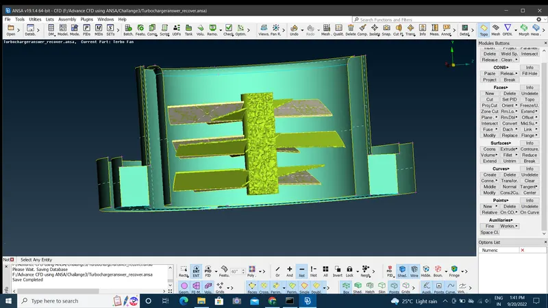
- Conclusion:
- Volume mesh for the given geometry achived.
- First perform surface mesh before volume mesh.
- Lessons Learned:
- Complete geometry cleanup
- Intersection error remiving.
- Assigning PIDs.
- Surface mesfing
- Voume Meshing.
Link:
https://drive.google.com/file/d/1rkkQSZPnbGFFl34tPWkcXjqRDT8uscbL/view?usp=sharing