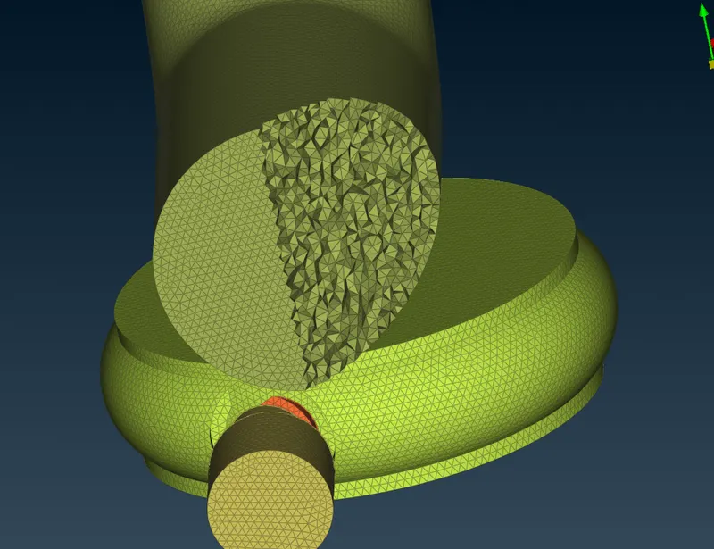
Week 3 Challenge : CFD meshing on Turbocharger
Aim:
Performing CFD meshing on Turbocharger using ANSA
Objective:
For the given model, check for the geometrical errors to make appropriate volumes. Create and assign PIDs as shown in the video. Perform surface mesh with the given target lengths as per PIDs.
- Blade stage-1 = 1 mm
- Blade stage-2 = 1 mm
- Impeller = 2 mm
- Shaft rotor = 1 mm
- Turbo casing = 5 mm
- Compressor casing = 5 mm
- Inlet casing cover = 5 mm
Perform Volumetric mesh for the required volumes.
Answer:
Turbocharger model received as input.
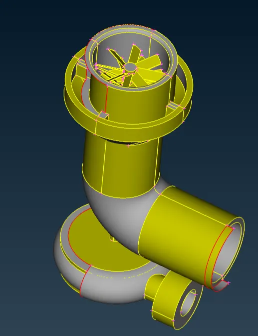
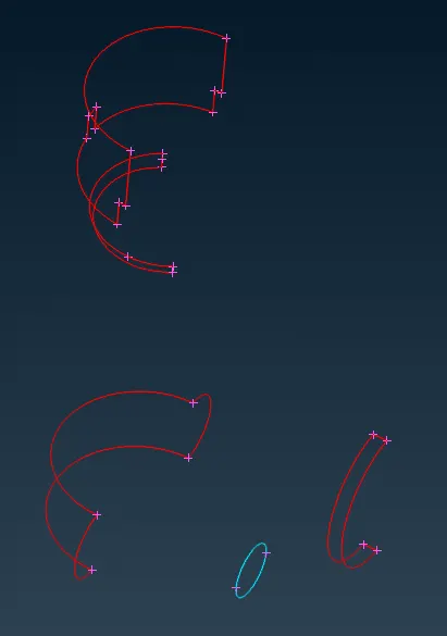
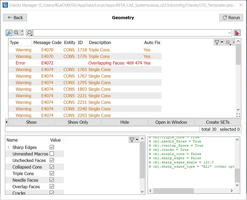
Single & triple CONS in the geometry which can be missing surfaces in the model or overlapping surfaces.
Surface overlapping has been found at multiple locations which can be observed by dual colors on the same surface.
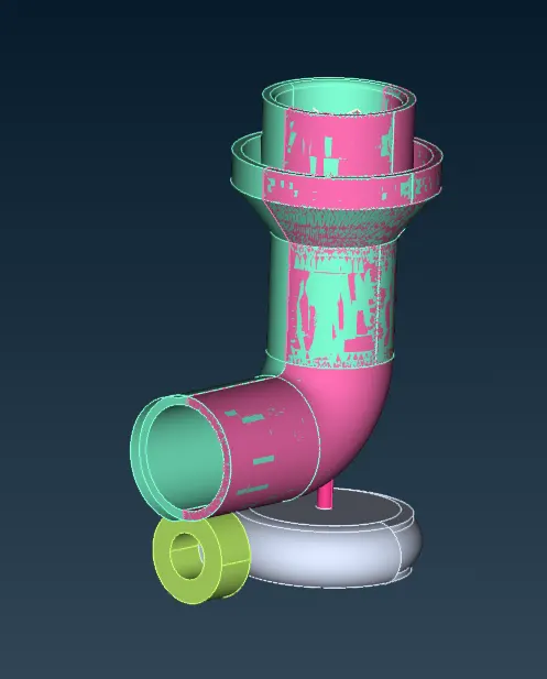
Geometry checks result.
Following toolbar has been used from TOPO deck to clean up geometry.
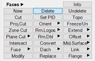
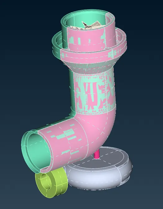
First, overlapping surfaces has been deleted using the delete command available in faces toolbar in topo deck. The surface is selected using the PID selection filter to select all surfaces with same PID which can be seen in below images for pink surfacce set.
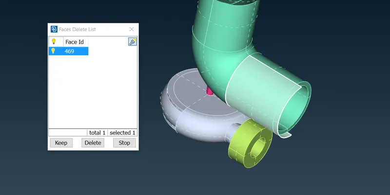
Other overlapping face has also been deleted.
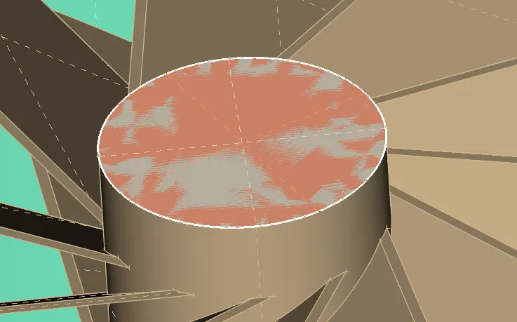
One more overlapping surface has been removed using universal delete command.
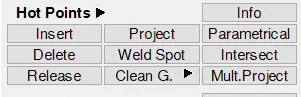
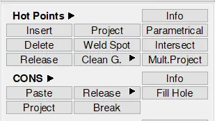
Extra CONS has also been found at the same place as shown in below imgae which has been released using "released" command found under CONS toolbar. These released CONS has been converted into single CONS which later converted into double CONS by joining faces using "TOPO" command. Extra hot points found on the same double CONS has been deleted using "insert" command found in Hot Points toolbar.
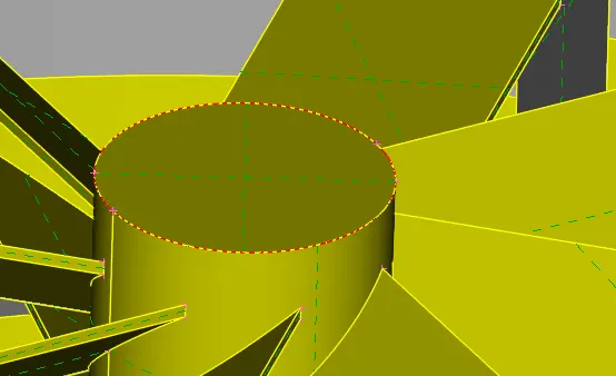
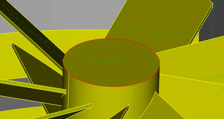
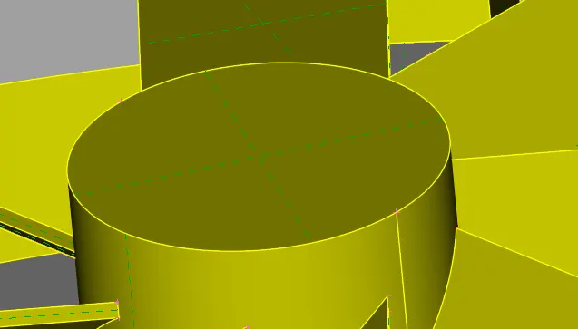
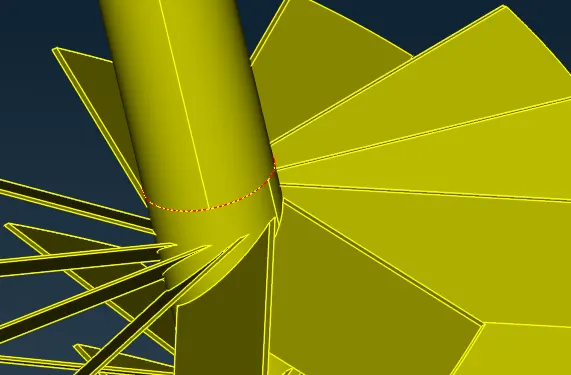
Single CONS has been found on two more places which are shown below. These errors are solved by using "Topo" command on connecting surfaces of that single CONS.
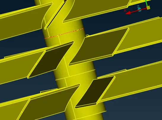
Near the blade section, 2 triple CONS was formed.
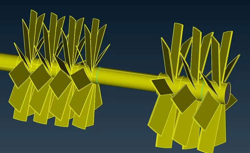
The surface shown in below image was present there.
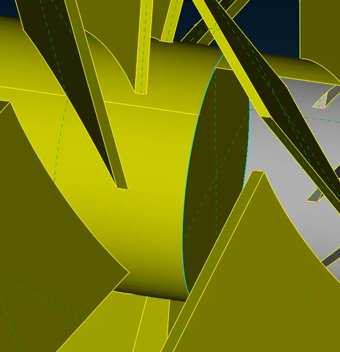
To perform volumetric mesh, the inside surface has been deleted using universal delete option from both places.
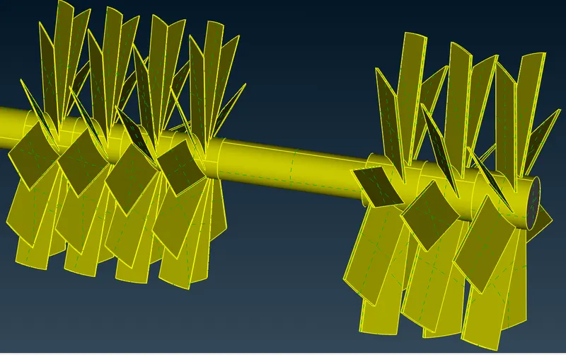
For below case, the both geometries, in pink & brown, has been extended & overlapped. We will cut down down the pink surface upto the end of brown surface by projecting the CONS onto it. And deleting the overlapping surfaces.
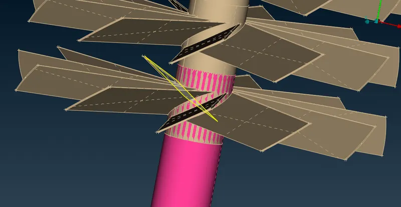
CONS of the brown face has been projected onto the pink surface using the "Project" command available under the CONS toolbar.
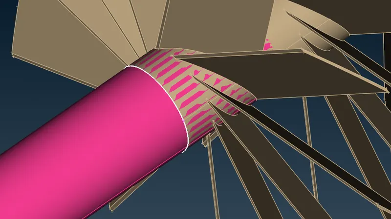
After projecting, the surface has been divided into two parts and CONS has less resolution as shown in below image.
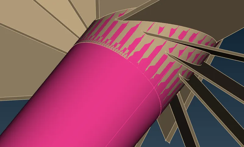
The resolution has been increased by using "Fine" command availble under Auxiliaries toolbar.
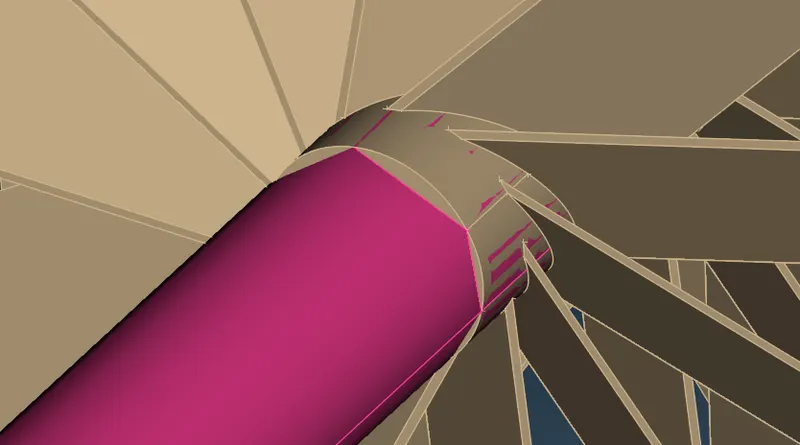
The rest of the pink surface has been deleted, and also the the interior brown surface also been deleted to create contiuous volume. Final section has been achieved as follows after using "topo" command.
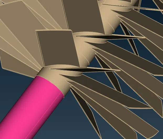
In following case, to create continuous volume, the end surface of the pink PIDs has been deleted. The CONS of the pink PIDs has been projected onto the blue one to delete the common section in between them.
After removing the central face from the blue PID, the "topo" command has been executed to form double CONS.
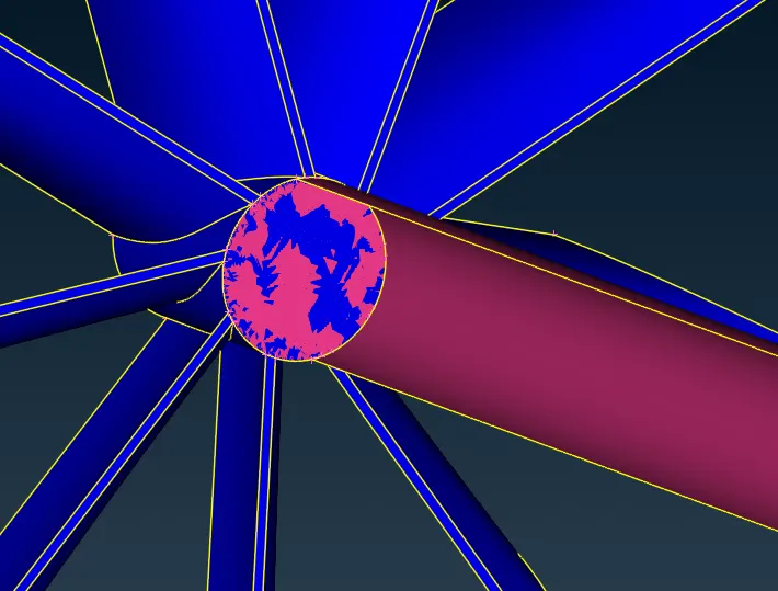
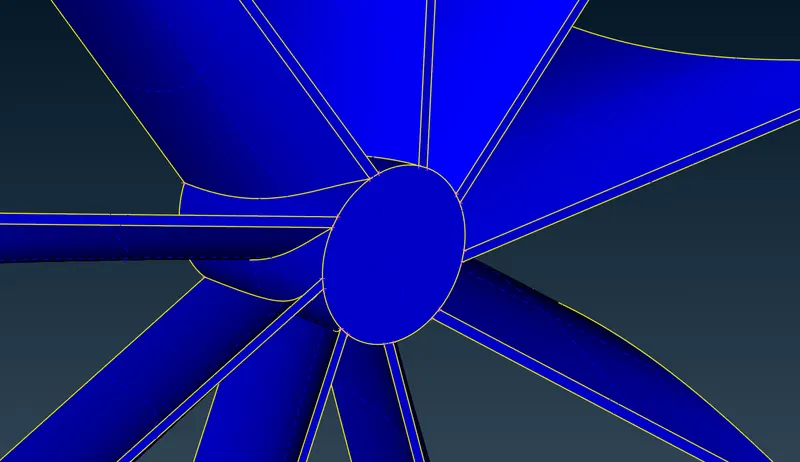
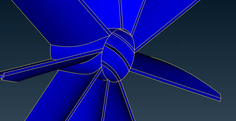
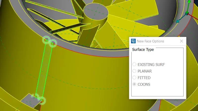
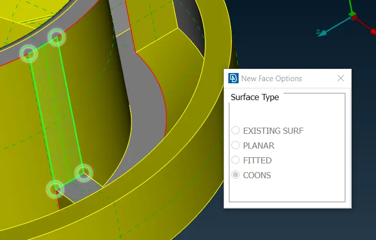
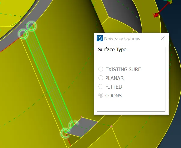
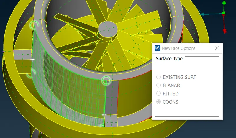
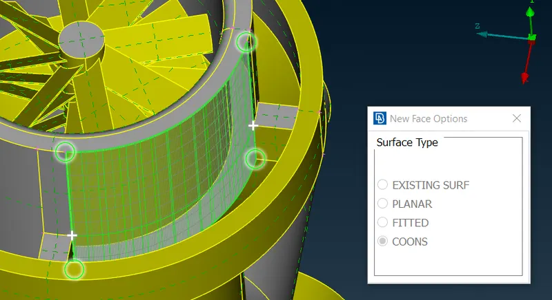
Creating new surfaces at the location of missiing faces using "New" command.
1.
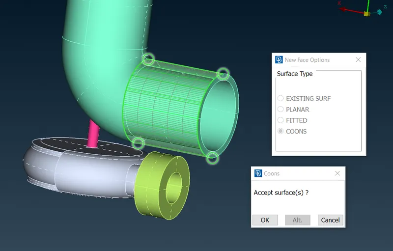
2.
While creating the below surface, as it has complex shpae, the surface was not created properly.
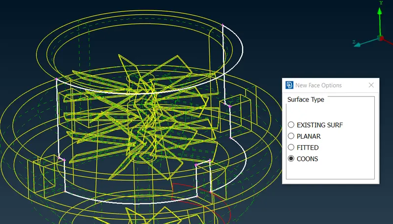
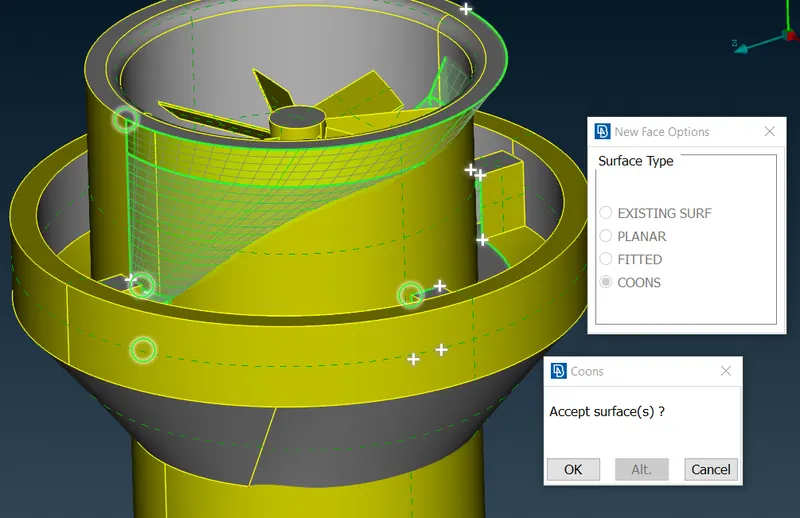
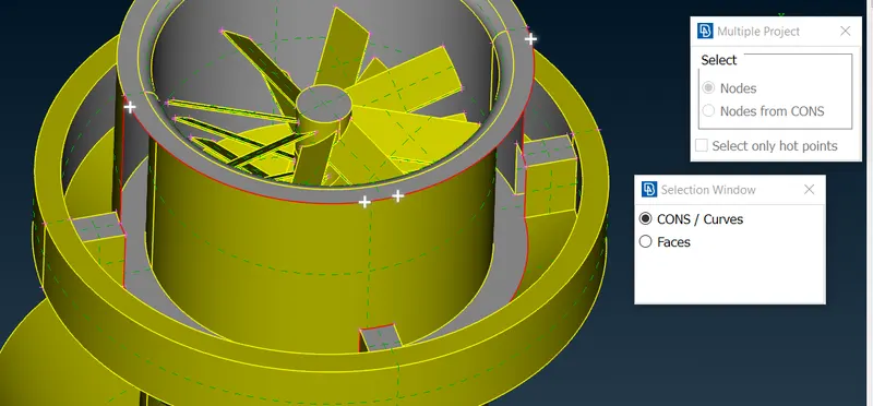
To solve this problem, hot points has been projected onto the top CON to make the smaller section surfaces.
Projected hot points using "multiproject" tool from "Hot points" toolbar.
Using "New" surface creation tool, the whole surface has been created by creating smaller section surfaces has shown below.
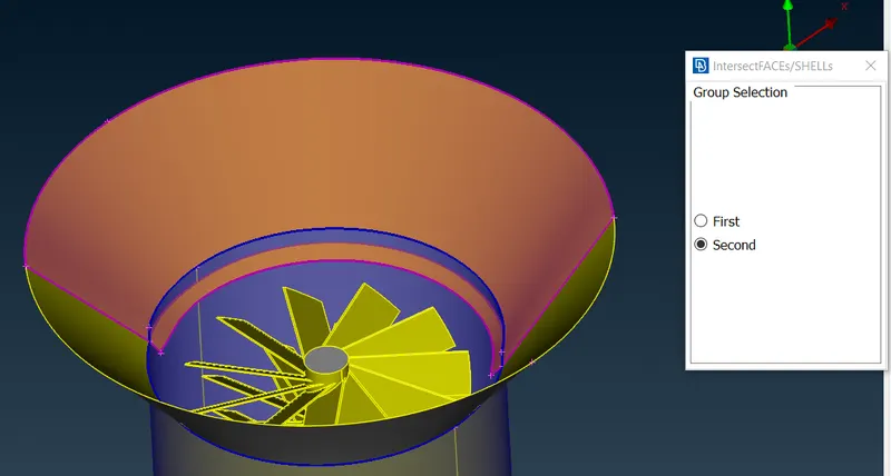
3. At one place, surfaces are found intersecting which has been corrected using "Intersect" command from the faces toolbar.
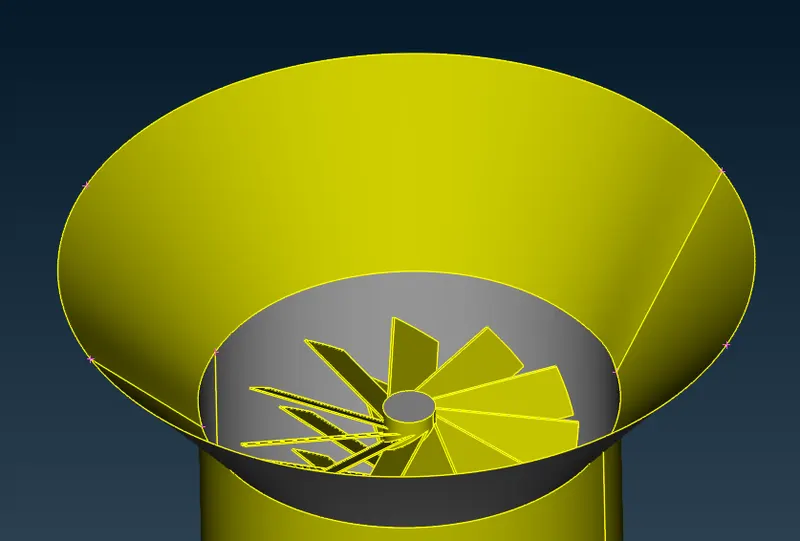
Now, following missing face, many options has been tried to create the new surface at that location with desired shape, but all options were failed to create proper surface with shape similar to shown in below image.
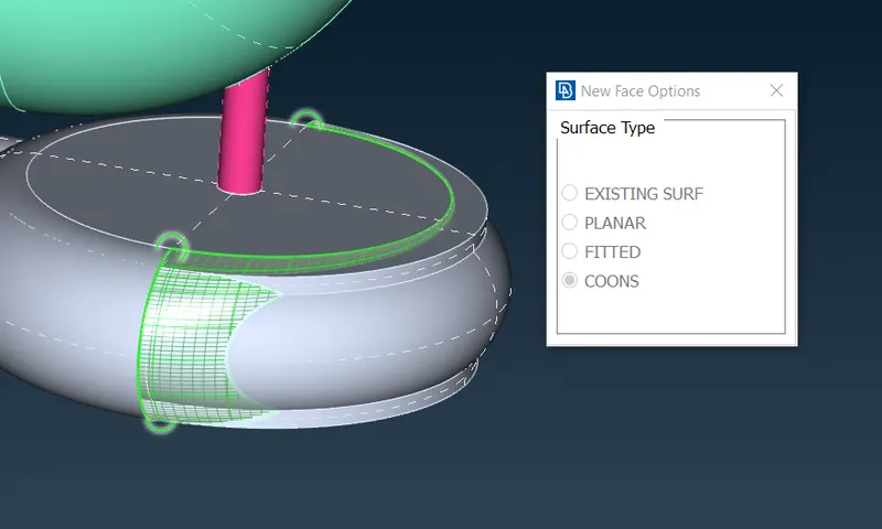
So, 7 hot points has been created each side using "parametrical" tool found in "Hot Points" toolbar to make smaller section of whole surface.
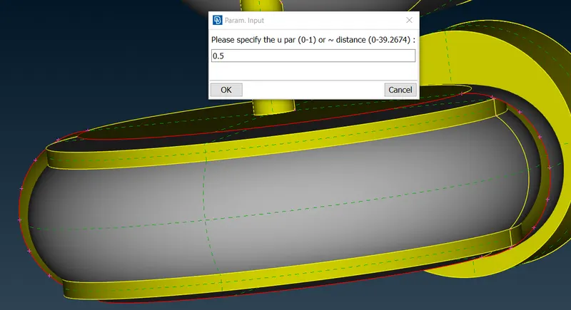
Using these hot points, new surfaces has been created using "New" command in following way.
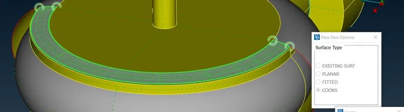
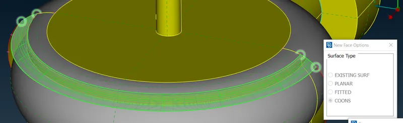
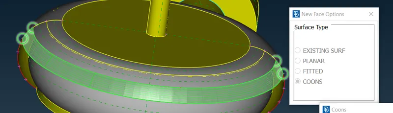
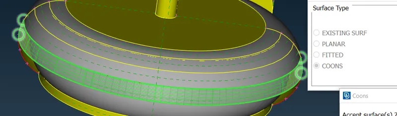
In similar way, all remaining surfaces has been created.
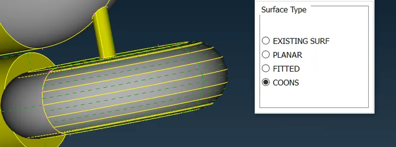
Making Close Volume & Assigning Suitable PID Names:
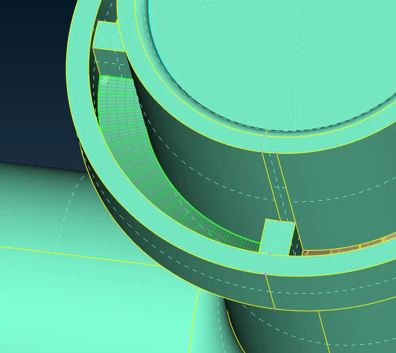
Closing gaps between outer casing & inside rotor
Inlet & outlet for outer casing (green) & bottom casing (gray) - Assigned PID after closing them
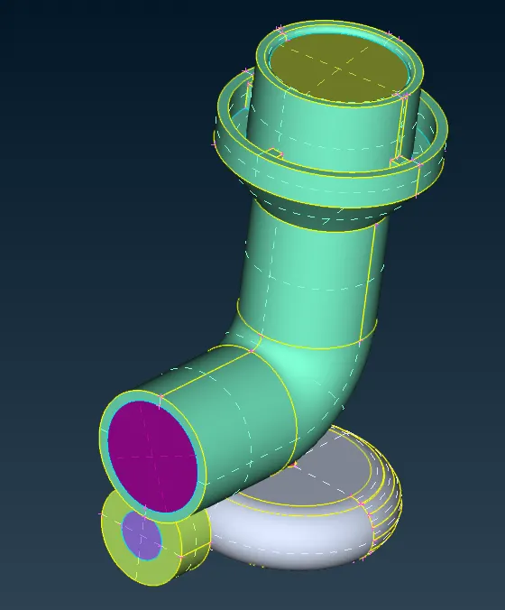
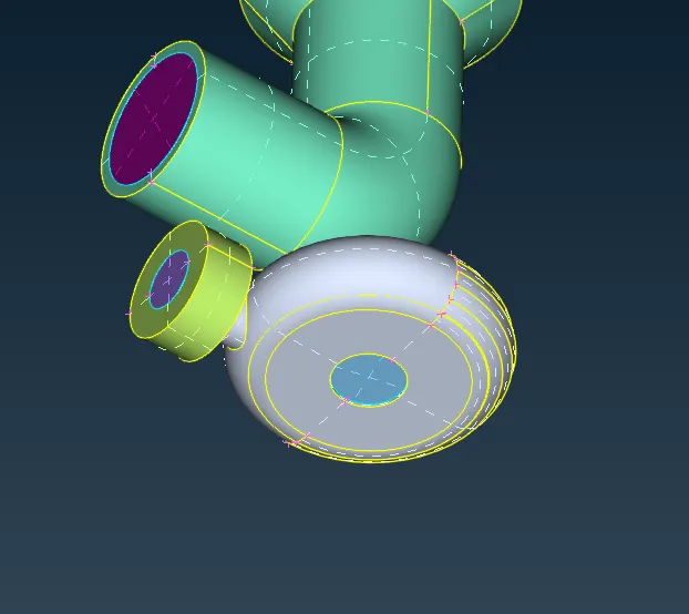
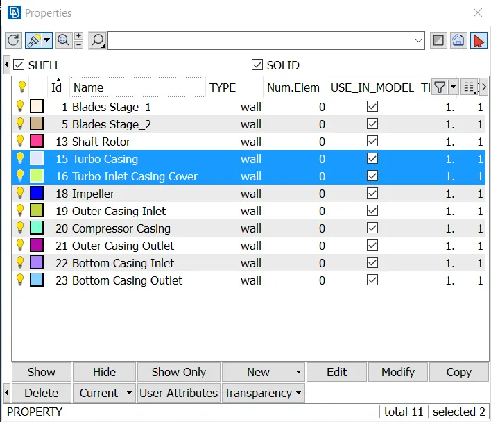
Assigning PIDs to other components
Unneccessary PIDs were deleted & some were throwing error while deleting which has been removed using "Compress" command. This command removes surfaces forcefully.
Surface Meshing:
Surface meshing is prerequisite before performing volume mesh.
Meshing has been performed as per the input for element sizes for various components. Following table shows the input provided before performing surface mesh.
| PID Name | Mesh Element Size (mm) | Length Command (mm) | Mesh Parameters (General) | Quality Criteria | ||
| Target Length (mm) | Element Type | Min Length (mm) | Max Length (mm) | |||
| 1. Blade stage-1 | 1 | 1 | 1 | Tria | 0.5 | 2 |
| 2. Blade stage-2 | 1 | 1 | 1 | Tria | 0.5 | 2 |
| 3. Impeller | 2 | 2 | 2 | Tria | 1 | 3 |
| 4. Shaft rotor | 1 | 1 | 1 | Tria | 0.5 | 2 |
| 5. Turbo casing | 5 | 5 | 5 | Tria | 3 | 7 |
| 6. Compressor casing | 5 | 5 | 5 | Tria | 3 | 7 |
| 7. Turbo Inlet casing cover | 5 | 5 | 5 | Tria | 3 | 7 |
Following steps of inserting mesh element information are same for all elmenets sizes.
Mesh Parameters
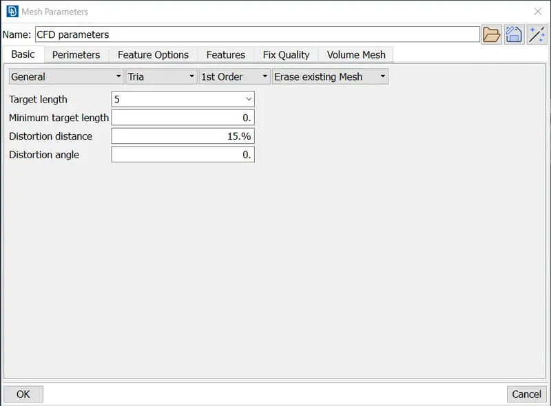
Quality Criteria
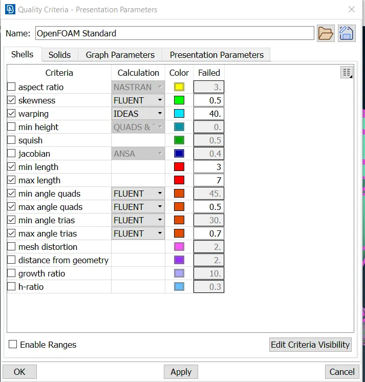
Length Command - Perimeters & Macros
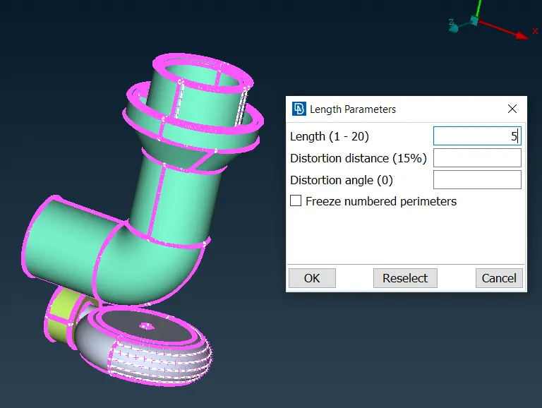
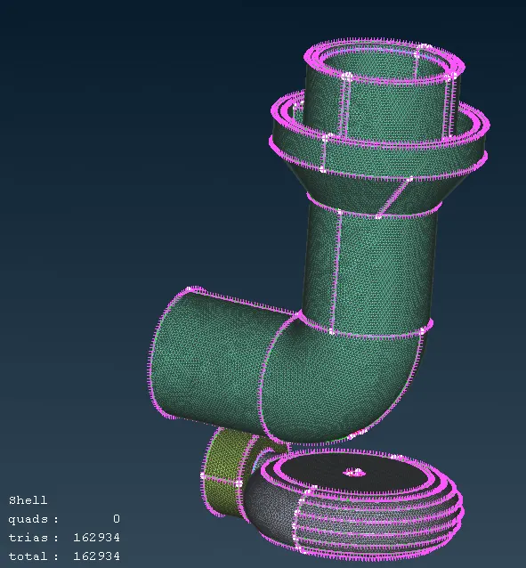
First components with 5mm length has been meshed with above inputs.
Components - Turbo Casing, Turbo Inlet Casing Cover & Compressor Casing
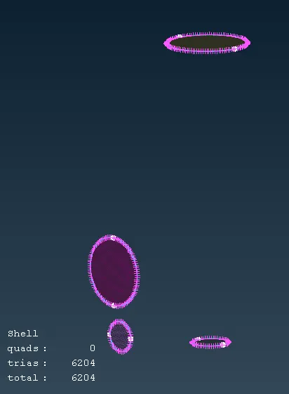
5mm - Inlet & outlet Closing Surface
2mm Mesh - Impeller
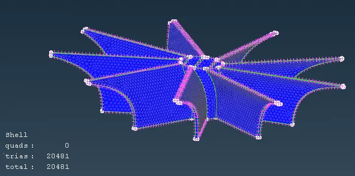
1mm Mesh - Blade Stage -1, Blade Stage -2, Shaft Rotor
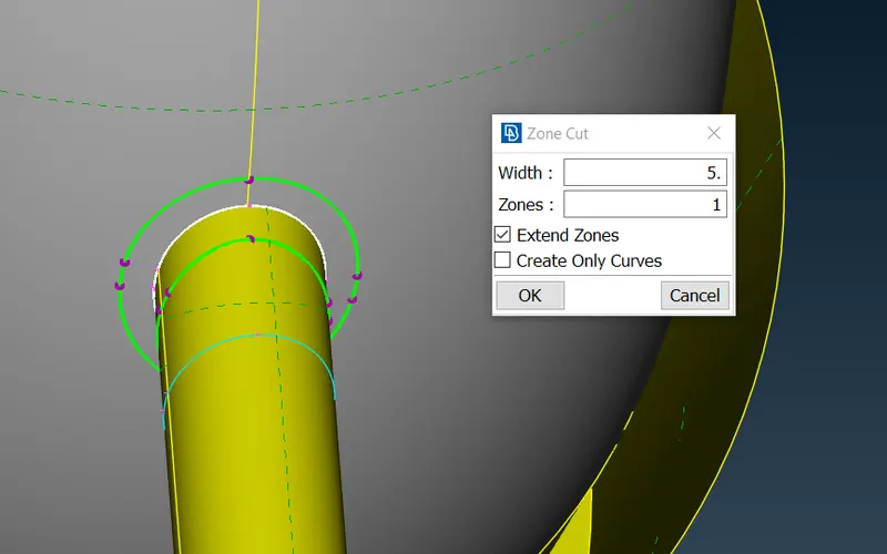
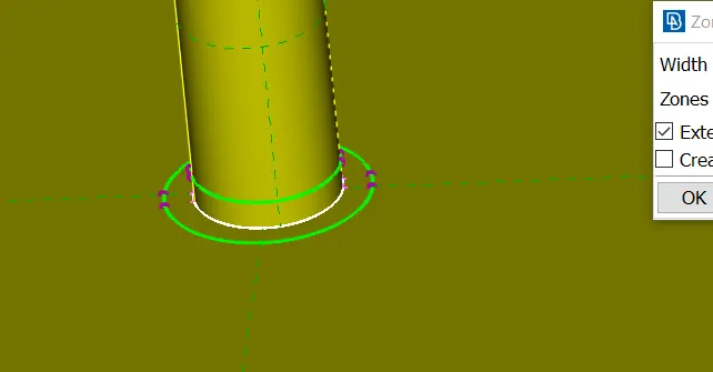
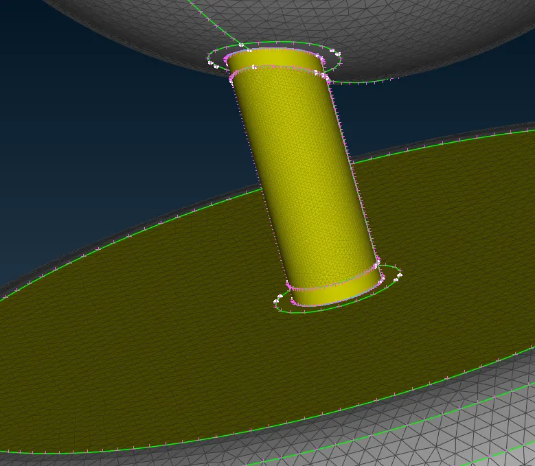
At the places where two different mesh sizes are coming in contact with each other, the "zone cut" command, from TOPO deck > Faces toolbar has been used to seperate small section between two faces from the common CONS to allow the transition of mesh sizes.
Following image shows the one example of it. At total 4 places this type of zone cut has been given.
Transition zone:
Final Mesh
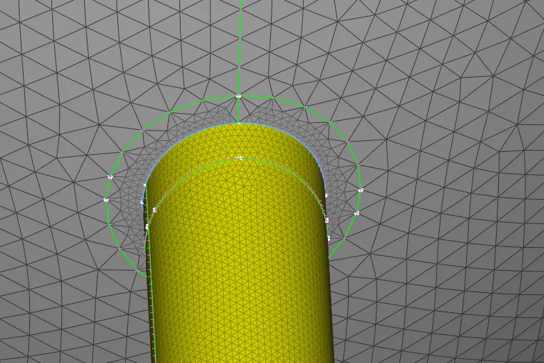
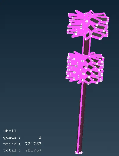
Final surface mesh of Turbocharger
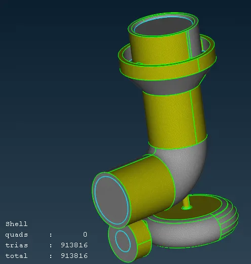
Volume Mesh
To perform volume mesh, following toolbar has been used.
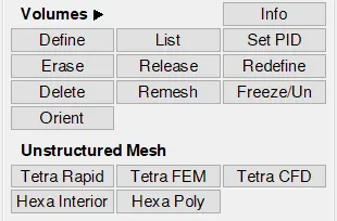
First "define" command has been used to determine number of close volume.
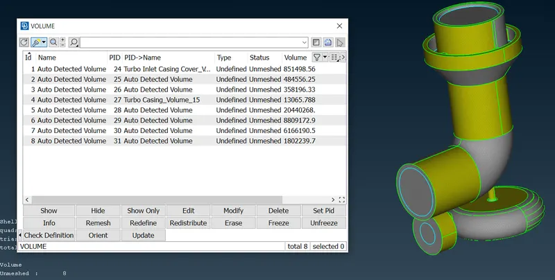
Out of these 8 volumes, the volume related to thickness of the components & components itself has been deleted.
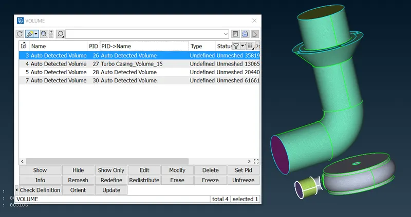
The "Tetra CFD" command has been used to perform volume mesh on these remaining 4 volumes. The final volume of mesh of turbocharger has been shown below.
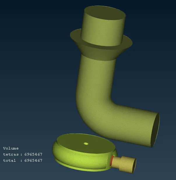
The cross section has been taken to visualize the inside mesh of the component.