Week 3 Challenge : CFD meshing on Turbocharger
Aim:
For a given model of a turbocharger check for the geometric errors to make appropriate volumes. create and assign PIDs accordingly also create a surface mesh and use that to create a volumetric mesh.
Objective:
Performing surface mesh with given target length as per PIDs.
blade stage 1 = 1mm
blade stage 2 = 1mm
impeller = 2mm
shaft rotor = 1mm
turbo casing = 5mm
compressor casing =5mm
inlet casing cover =5mm
writing the detailed report on your surface meshing and volumetric mesh.
Steps:
- Import the geometry.
- Check for geometrical errors.
- Geometry cleanup.
- Assigning relevant PIDs.
- Meshing.
Step 1: Import the geometry
The predesigned geometry of the turbocharger is imported into the ANSA.
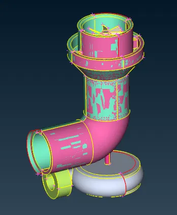
Step 2: Check for geomterical errors.
The checks tool is used to check the geometrical errors like cracks, single CONS, intersections, penetrations etc.
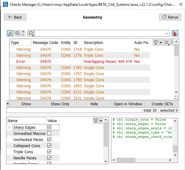
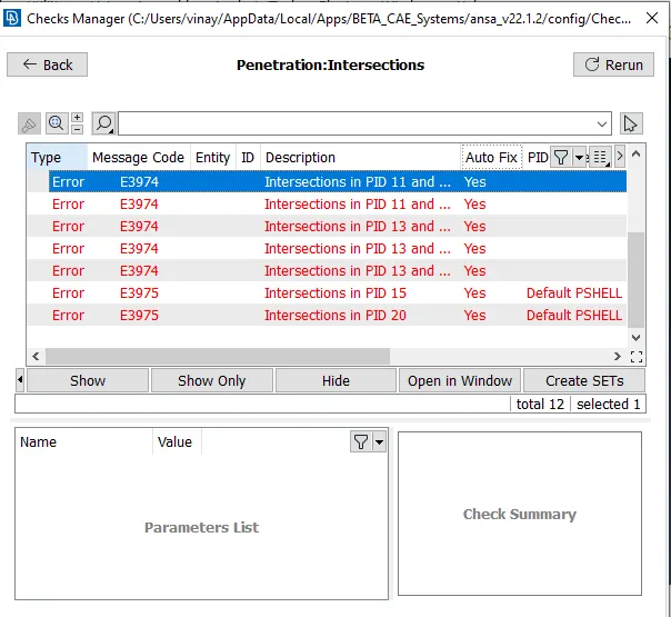
Step 3: Geometry cleanup.
First, the geometrical errors like single CONS and cracks are fixed by patching the faces, deleting extra surfaces etc using project CONS, new face, topo, delete face etc. tools. Then, when fixing the intersection and penetration errors, single CONS form and have to be fixed.
Delete the unnecessary overlapping surface by using the universal delete option
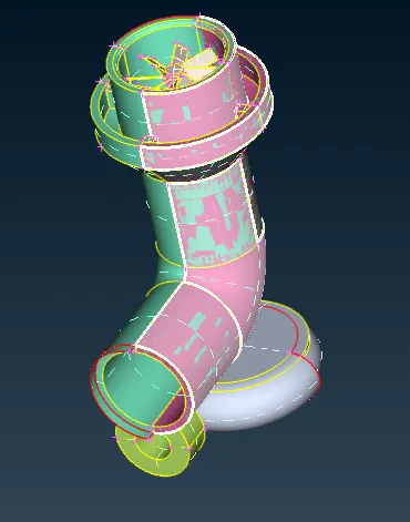
Start filling the surface and cleaning the single cons by creating the surface whereever required.
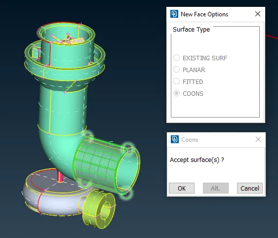
In cretain area use parametrical option to create multuple hot points to create a smooth curved surface.
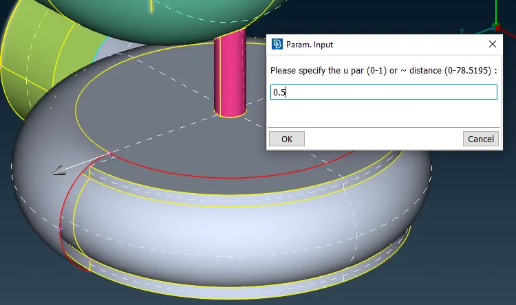
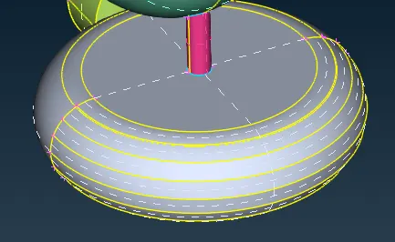
The intersect option is used to delete the surface which has no separate entity, therefore a separate entity is formed and can be deleted easily after.
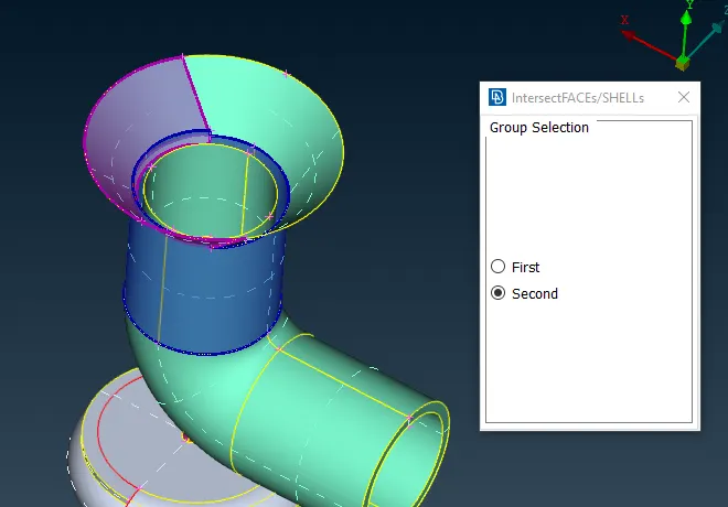
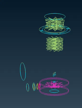
After we correct all the surfaces and the single cons we will check for triple cons. All the blue lines indicate the triple cons.
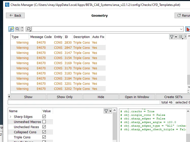
Before going for the meshing we will check the geometry for any errors apart from triple cons. This can be done using the checks manager.
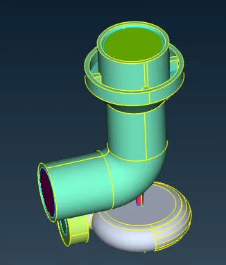
We will also close all the openings.
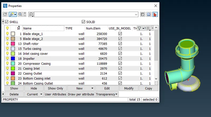
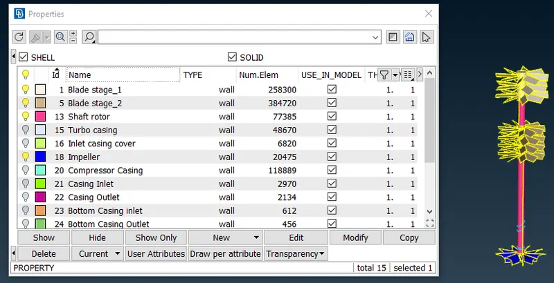
Step 4: Assigning relevant PID's.
Step 5 Meshing:
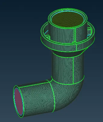
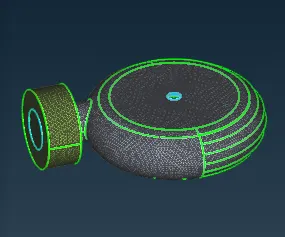
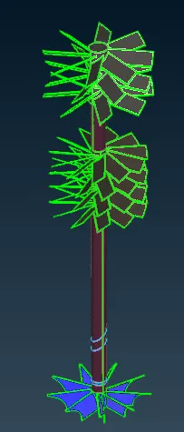
After assigning different PIDs to different parts, we can proceed further to generate mesh. The mesh parameters like minimum and maximum target length etc are specified.
The mesh element lengths for different components are given below:
- Blade stage-1 = 1 mm
- Blade stage-2 = 1 mm
- Impeller = 2 mm
- Shaft rotor = 1 mm
- Turbo casing = 5 mm
- Compressor casing = 5 mm
- Inlet casing cover = 5 mm
Volumetric Meshing
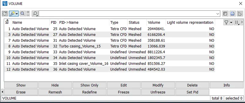
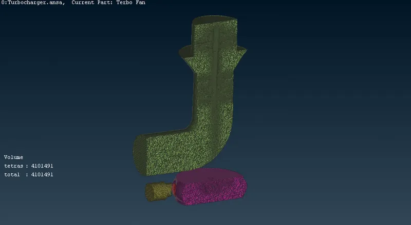
After generating the surface mesh the define volume tool is used to detect the volumes. Both fluid volumes and solid volumes will be detected, but the focus is to generate the volumetric mesh of the fluid domain. So the solid volumes are deleted. The tetra CFD mesh is used to mesh the solid volumes.
Conclusion
Volumetric mesh with 4101491 elements is generated inside the fluid domain of the turbocharger geometry
The meshed model is uploaded at below link.
https://drive.google.com/file/d/15RAnMy7gCiHMujmZLfzyxdMSenFXrIOl/view?usp=sharing