Week 3 Challenge : CFD meshing on Turbocharger
AIM : To perform volumetric and surface mesh for the given turbocharger model and assign PID's as requested
PROCEDURE :
1. download and import the model into ANSA software and using shadow command turn the view of the model to 3D view which by default comes in wire frame model
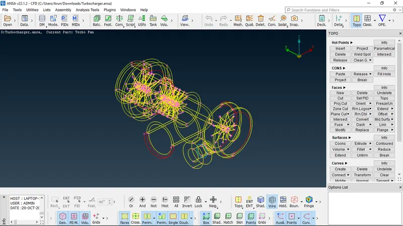
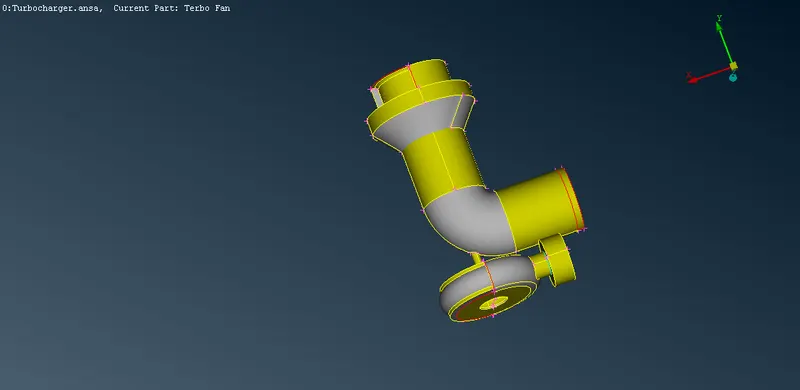
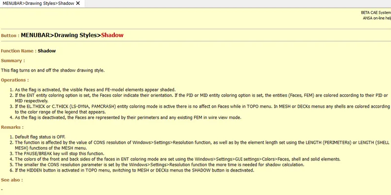
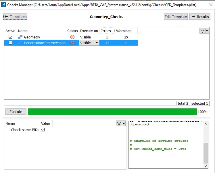
2. Using the geometric checker option check for any geometric errors and resolve them
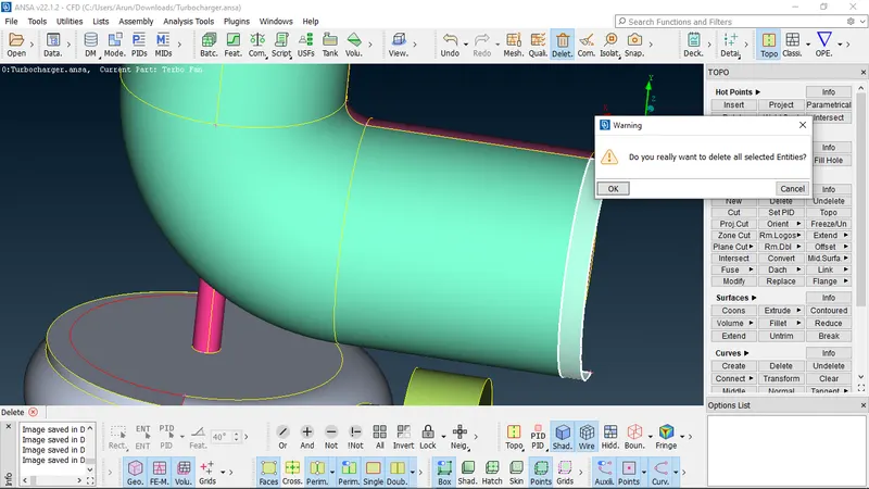
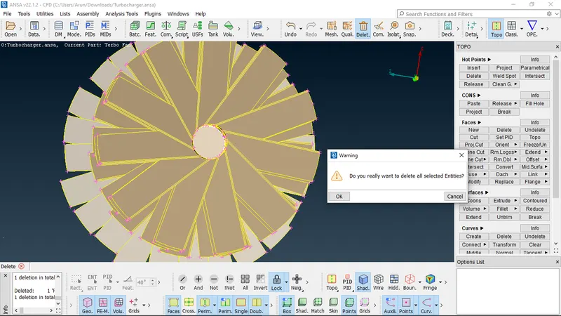
. using the project command the cons will be projected on to the surface making it a different geometry, which enables us to delete the selected fragment of the face,
helping us to grt rid of the unwanted projected surface
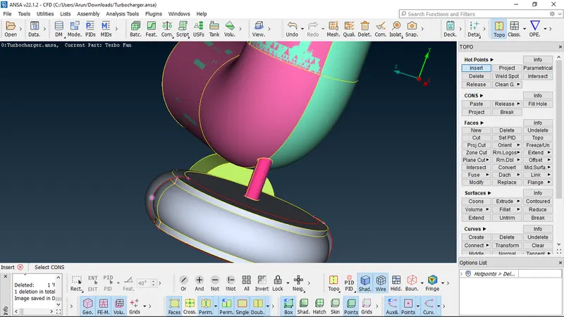
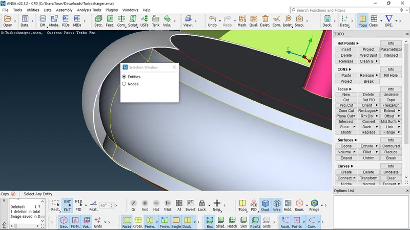
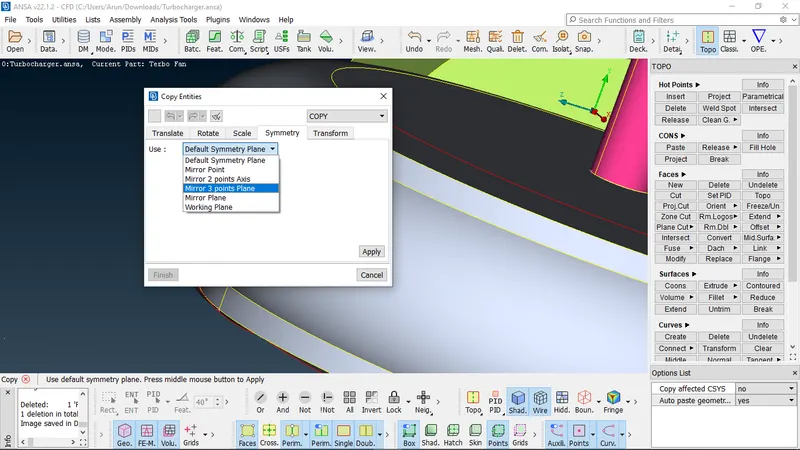
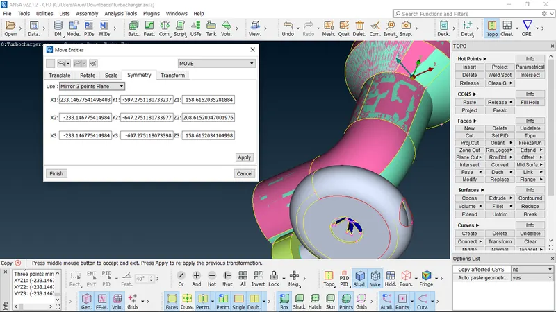
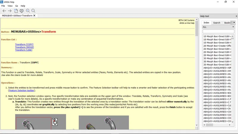
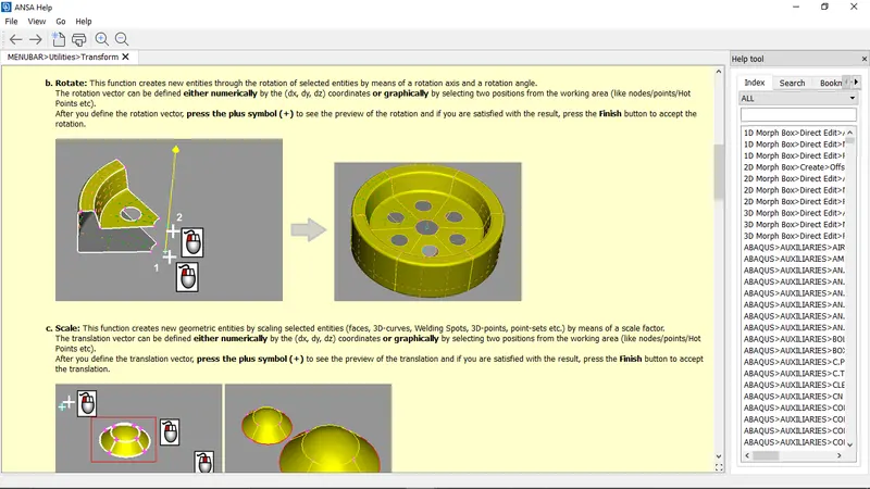
. The opening in the surface is closed using copying a symmetrical surface by transform command, where in the surface/entity to be copied is to selected and the path way through
which its to be copied is also defined by the hot points. The hot points serve as the cordinate system of the surface to be fixed
then the remaining hole is filled used fill hole option thus completing the surface and the topo command which elimantes the single cons in the surface
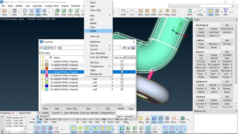
. The intersection surface in the geometry is deleted from the PID's manager
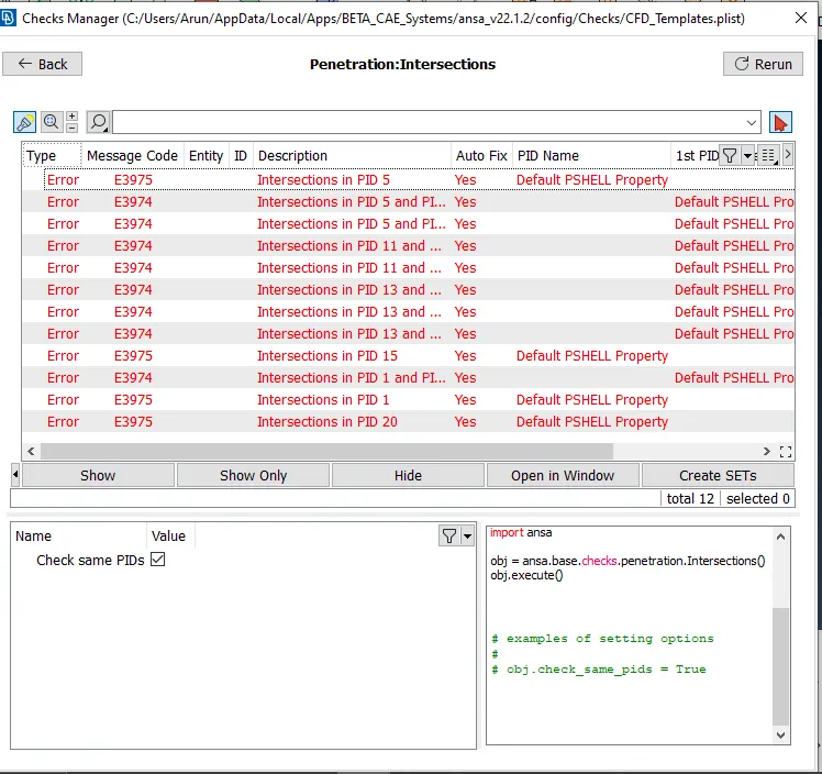
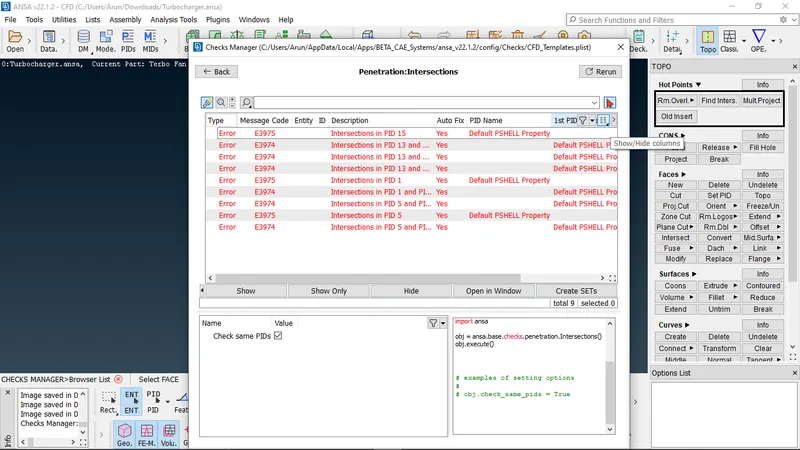
. Again upon the geometry check the further intersection and penetration errors are diagnosed and fixed by deleting and recreating the surface, using topo feature, in some cases
projecting the single con or the surface which is intersected and merging it to the part of the surface which can be healed and deleted, thus deleting any unwanted surafce and
intersection and penetration errors
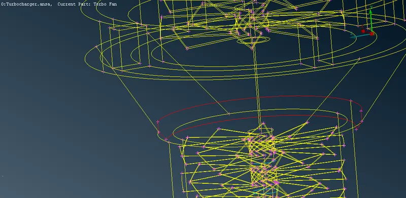
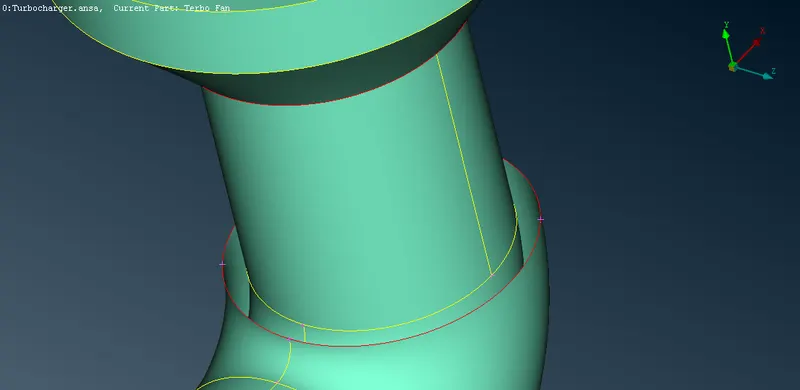
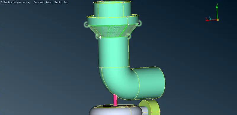
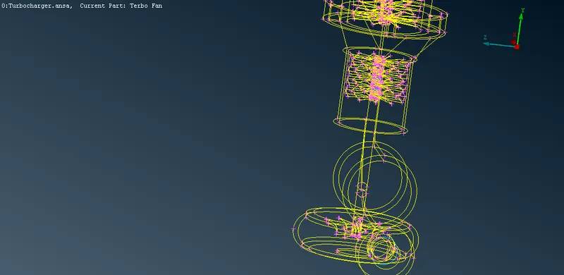
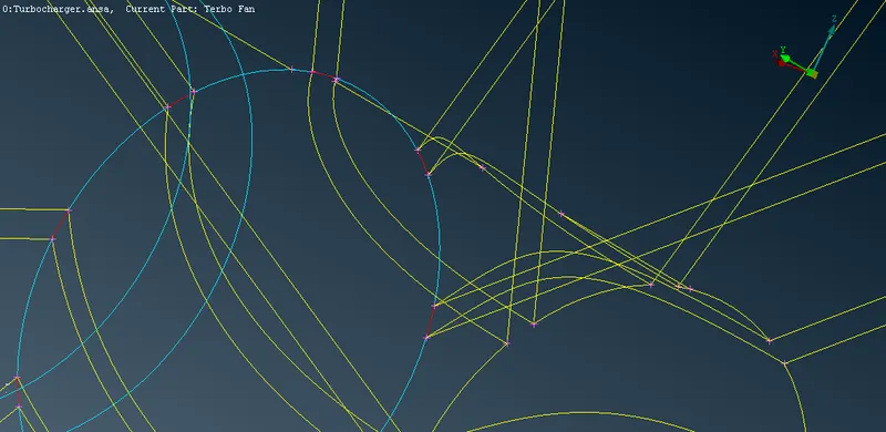
. surface penetration errors before and after fixing
deleting the intersected surface and projecting the single cons formed after to the shaft surface
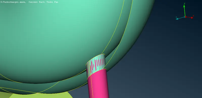
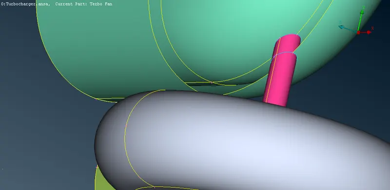
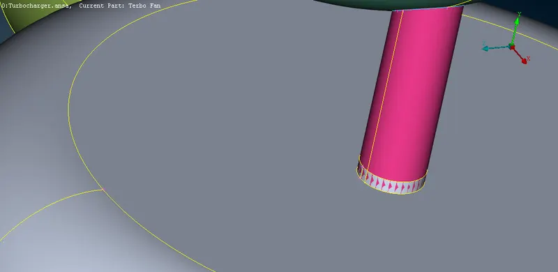
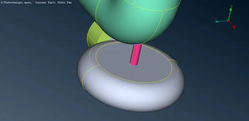
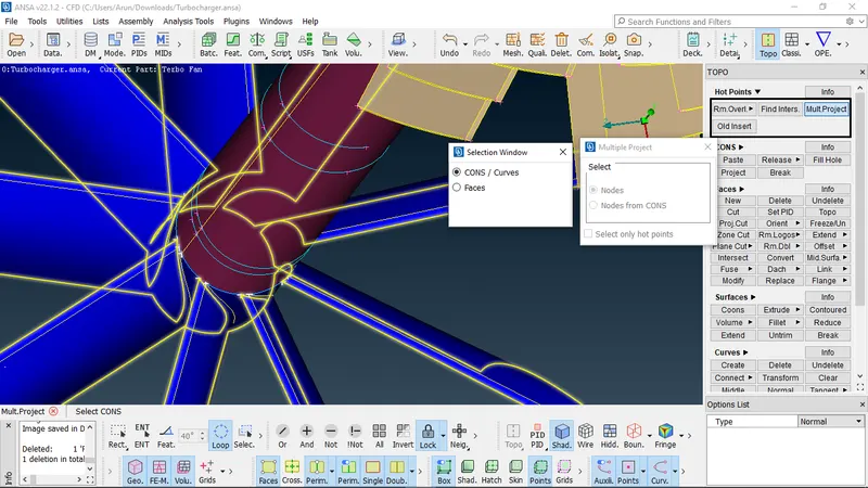
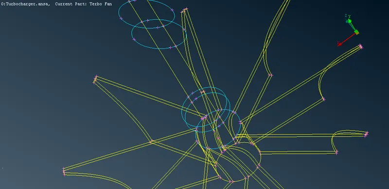
. resolving the errors in the turbine shaft
deleting the intersect surface after projecting them into the deletable entity and clearing it up
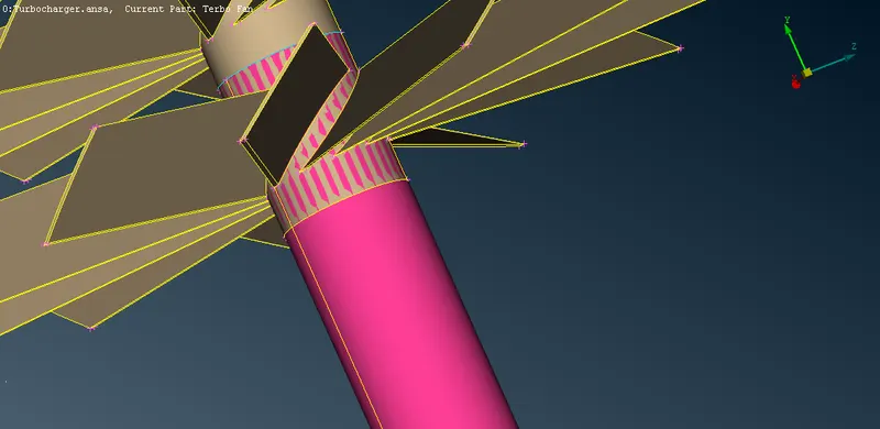
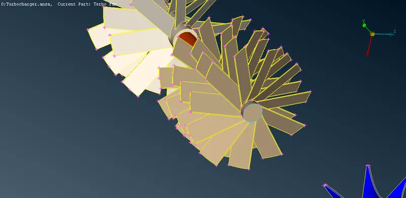
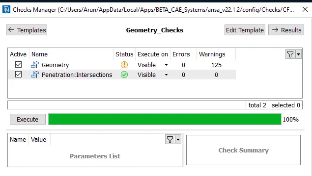
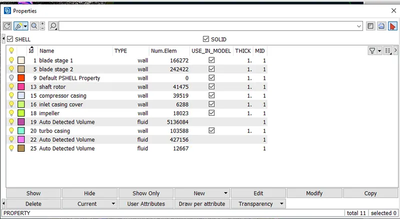
3 . once the geometry is cleaned up prep for the meshing process by closing all the openings and assign PID's
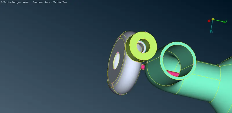
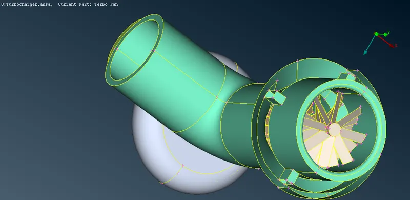
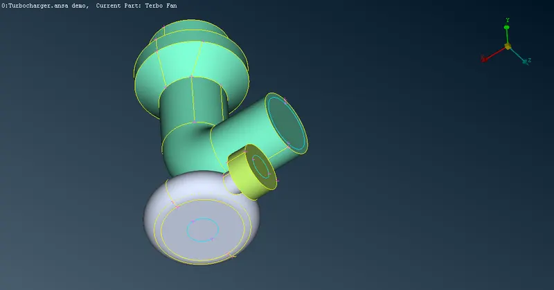
4 . meshing the surface by specifing the element length for each component
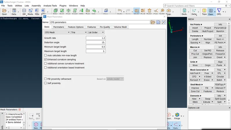
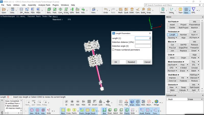
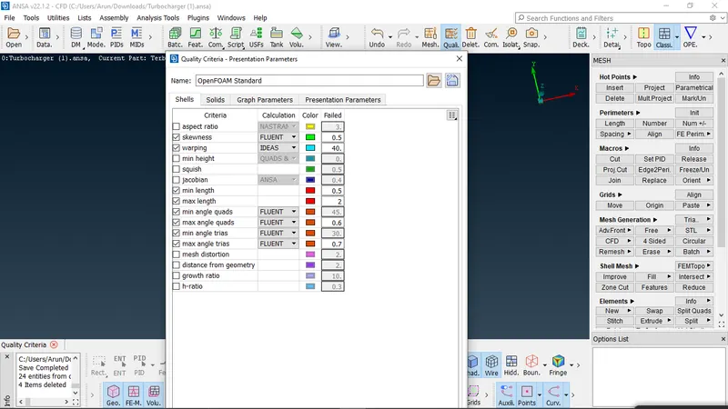
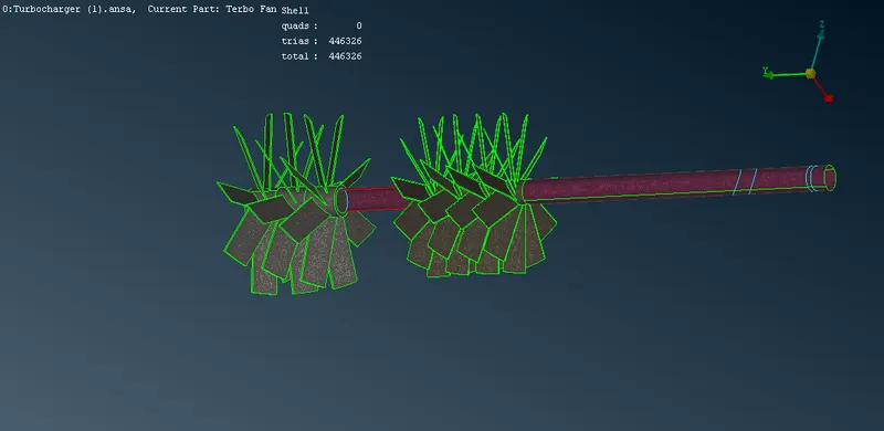
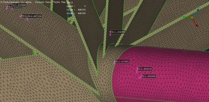
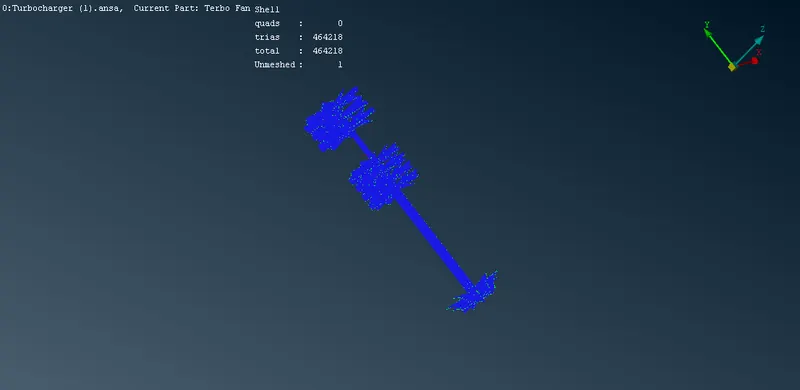
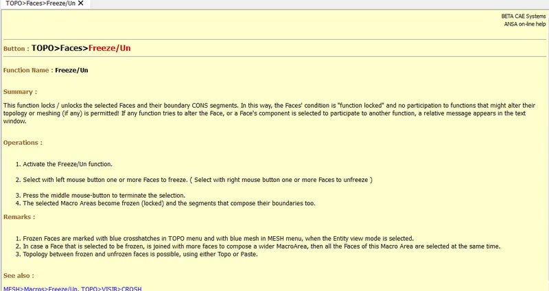
. once the fan blade and rotor shaft are meshed the geometry is freezed using freeze command as it should not be involved in further process of meshing where the
meshing criteria is changed . this is repeated once after the impeller is also meshed
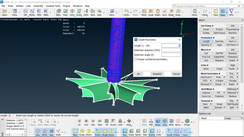
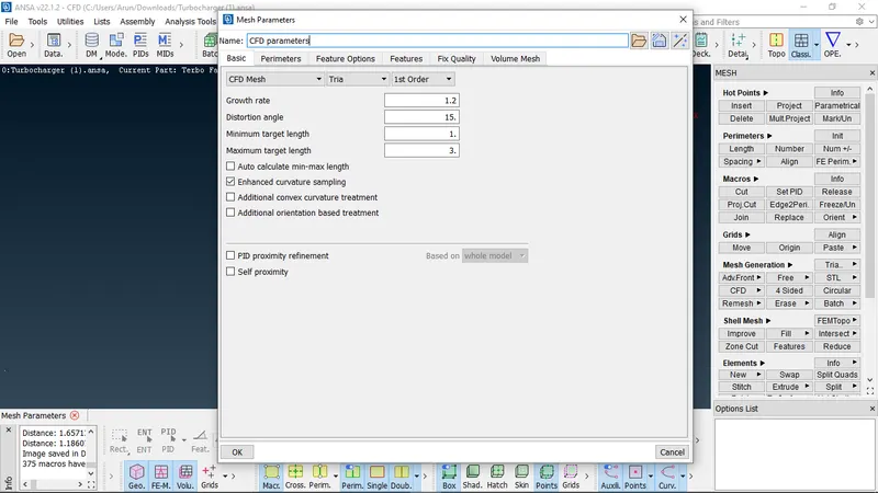
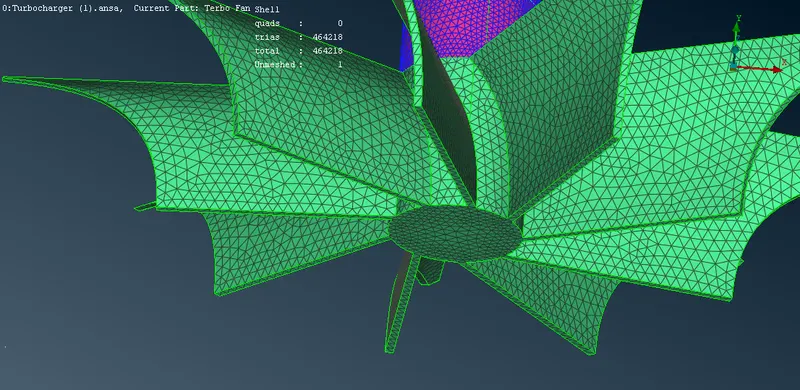
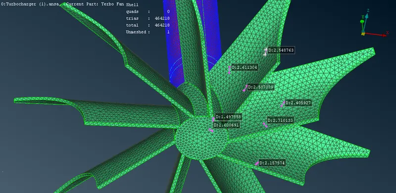
. rest of the components are meshed
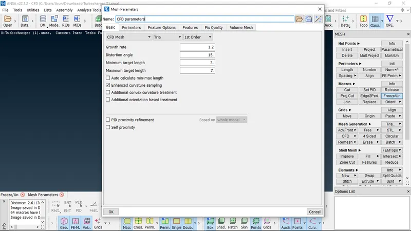
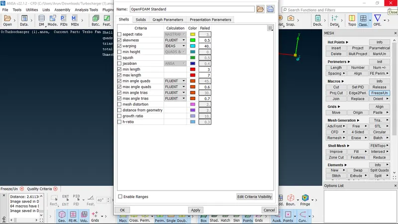
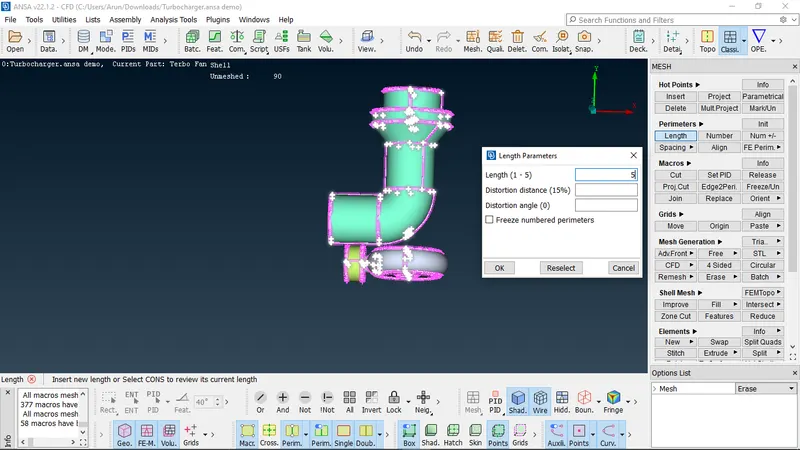
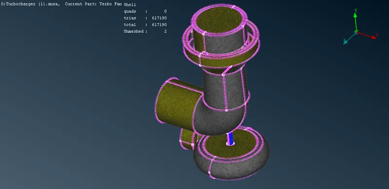
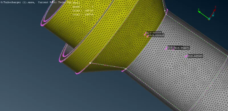
5 . further clean up of the mesh is performed by the improve option where it fixes the broken and course meshes itself by minor tweaks
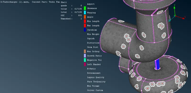
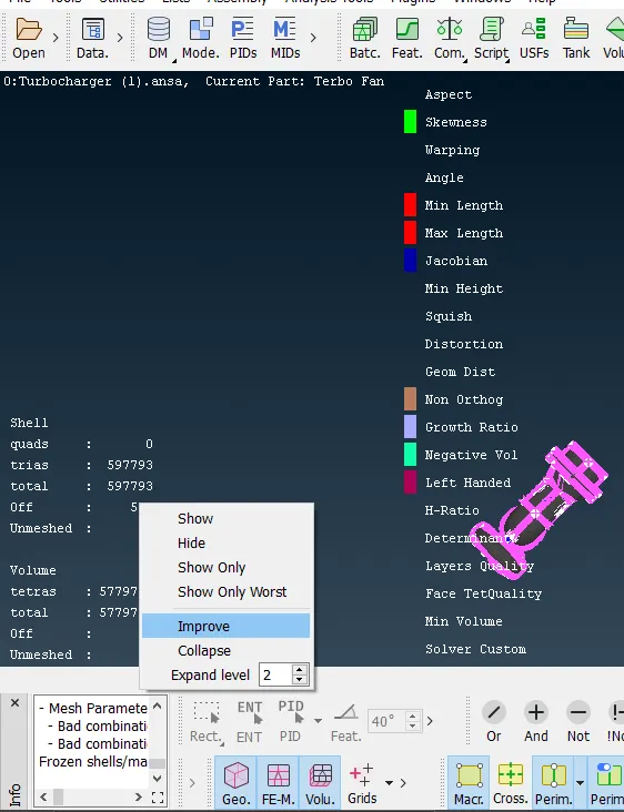
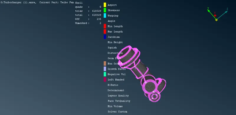
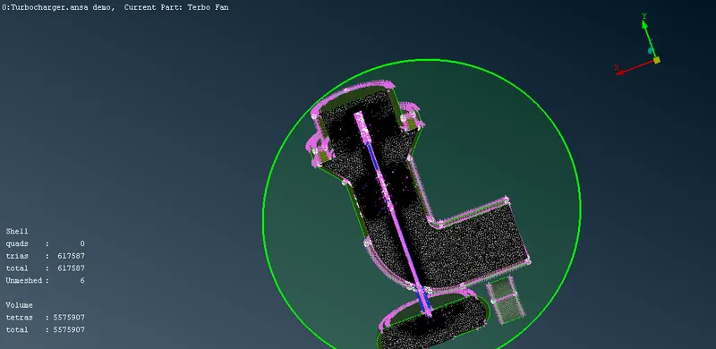
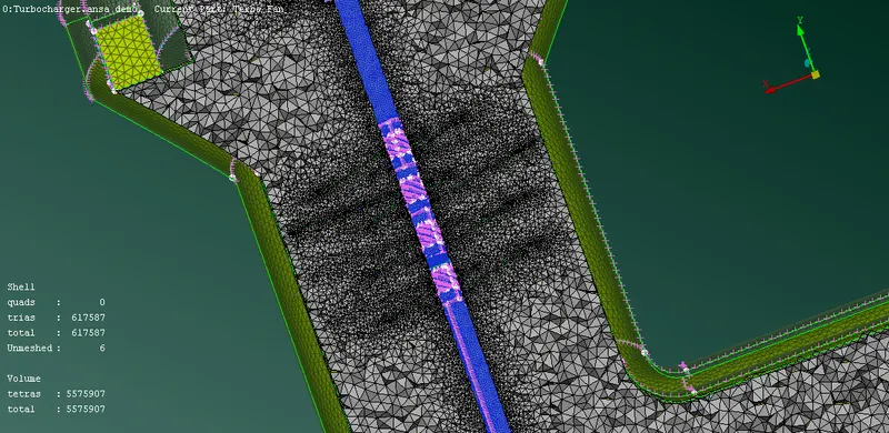
6 . volumetric mesh is then performed
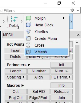
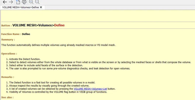
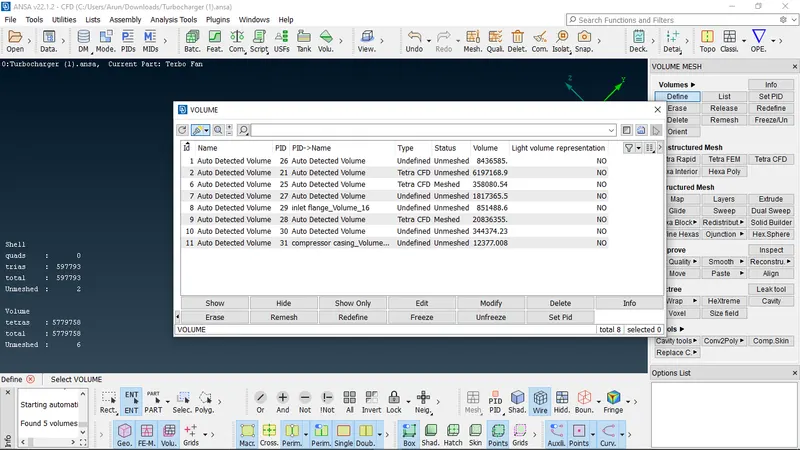
select the V. mesh option, then go for define option where it detects the possible volumes that can be meshed in the geometry, from where the needed flow path geometry
can be selected and the type of v.mesh tetra cfd can be specified and as well the surface volumes can be avoided too
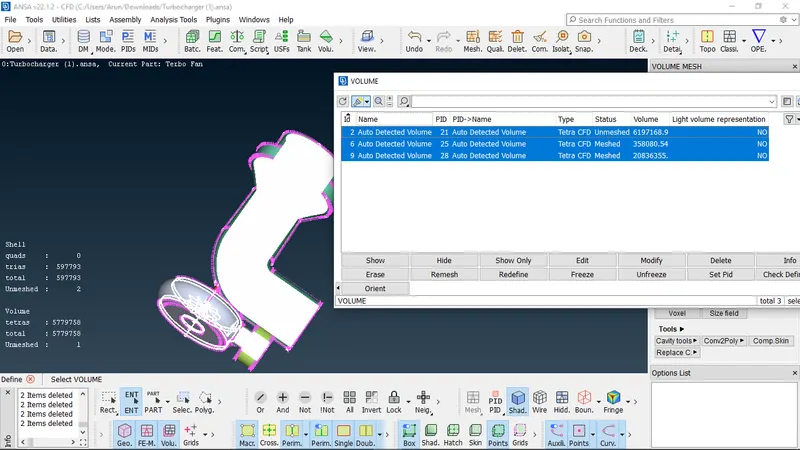
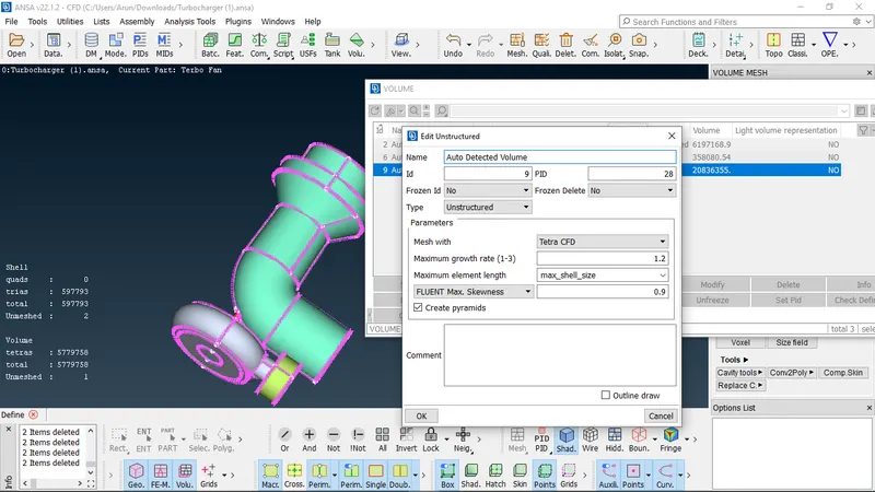
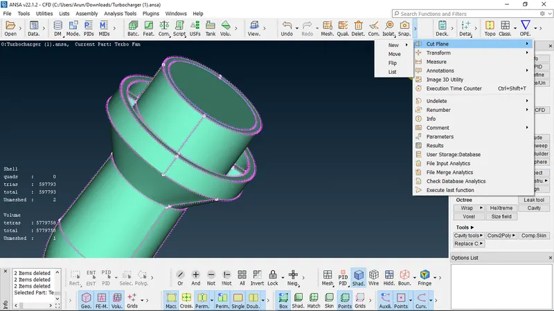
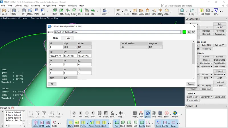
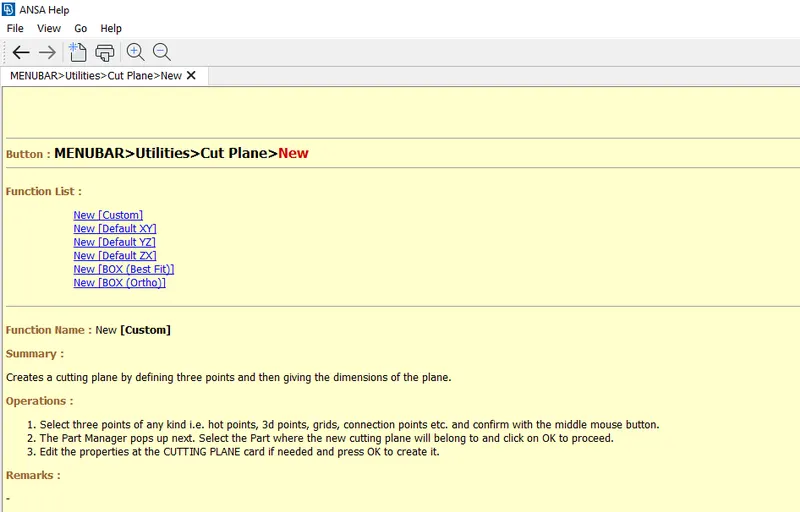
. once the volumetric mesh is completed to view the meshed part which is the inner part of the geometry, can be viewed by sectioning the model into half by using cut plane
option where the plane about which the model is to be bisected can be defined
. link to the model uploaded in drive
https://drive.google.com/file/d/1mVjYRCZXDZOeWFMVRSre7nZSaTSSeNHc/view?usp=sharing