Week 3 Challenge
1.How hydrology and geotechnical studies (preliminary and detail studies, zone of influence) are used in fixing span as per IRC standards and type of bridge. Mention the clauses applicable for the same.Determine the scour depth at the pier and abutment.
Ans.
- First of all before starting any work for bridge topographic survey is to be done. From the survey data designer can get the location data such as
- levels/RL of bridge location
- embankment height RL in both the sides of the stream
- HFL, LBL, OFL.
- The RL of the bed of the bridge location
- From RL of the bed location the cross section/profile of the bed can be determined.
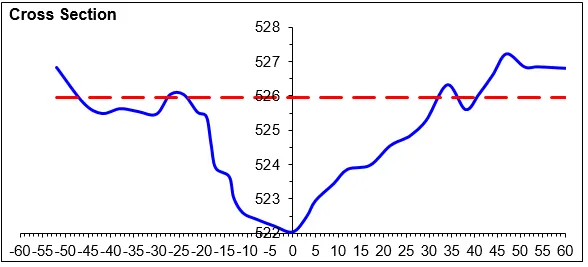
- From the survey data of the bed RL the total length of the bridge is generated.
- The total span length is to be fixed in such a way that the abutments of bridge should be beyond the level where the HFL intersect the embankment of the stream or river.
- For fixing up the span there is no such constrain for fixing up the span length but it is finalized according to the site and ground conditions.
- It is preferable to avoid pier if the total length of the bridge can be accomodate with a single span within reasonable length.
- If the length of bridge is so high then intermediate piers need to be provide.
- It is recommended to avoid mendering locations of the streaam for fixing up the abutment/pier.
- Generally the spans of a bridge kept similar as per the design consideration but it is not mandatory for keeping all the span length as same. As per physical site requirement the sizes of span may varry.
Types Of Bridge:-
Bridge-Bridge is struture build to cross the obstacle without closing the way beneath such as water, valley or road.
The type of bridge has been classified according to different component. Such as
- Bases on Super structure
- Slab bridge-A short-span bridge consisting of a reinforced-concrete slab resting on abutments/pier.
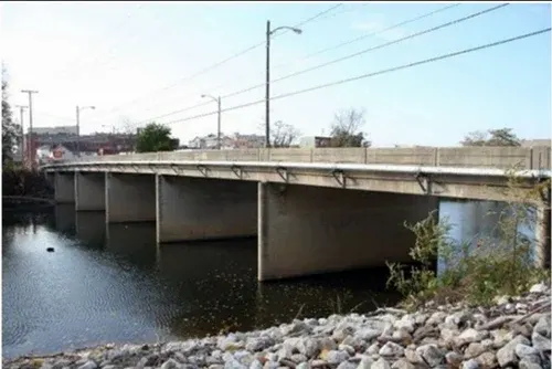
- Beam bridge-Beam bridges are the oldest and simplest bridge design consisting of vertical piers and horizontal beams.
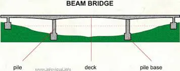
- Truss bridge-The truss bridge consists of an assembly of triangles. Truss bridges are commonly made from a series of straight, steel bars.
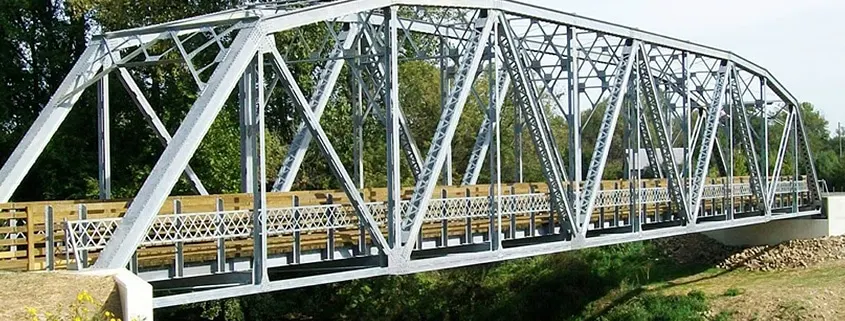
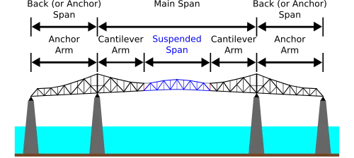
- Cantilever bridges- Cantilever bridges are based on structures that project horizontally into space, supported at only one end - like a spring board.
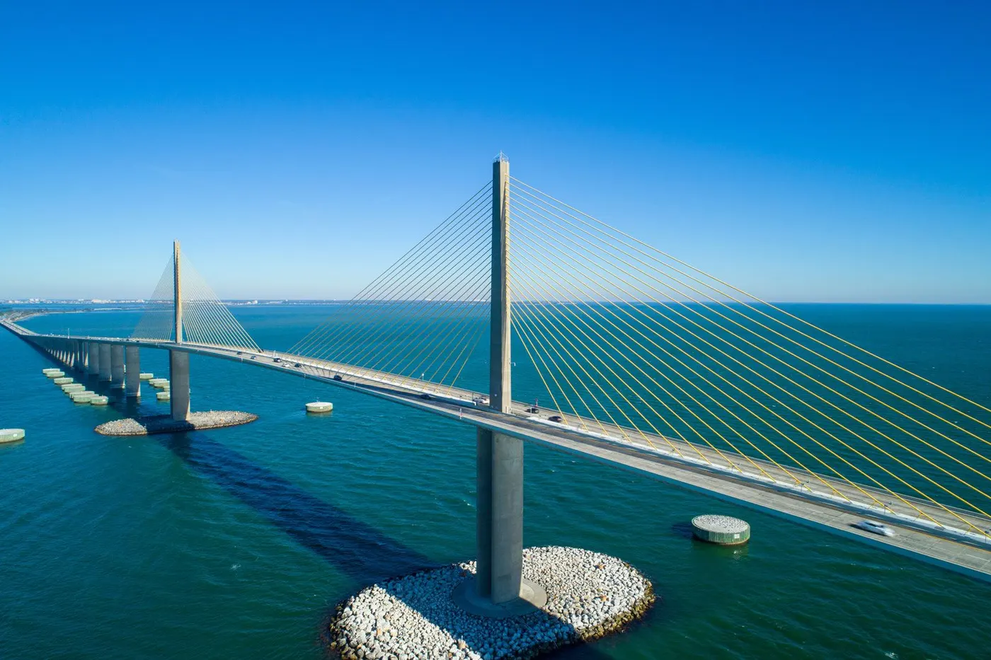
- Cable strayed/Suspension bridges- Cable-stayed bridges may appear to be similar to suspension bridges, but in fact they are quite different in principle and in their construction. There are two major classes of cable-stayed bridges: Fan type, which are the most efficient, and Harp or parallel type, which allow more space for the fixings.
- Bases on Material
- Timber Bridge
- Stone Bridge
- Steel Bridge
- RCC Bridge
- PCC Bridge
- Composite
- Bridge on Relative position
- Deck trough bridge
- Suspension bridge
DATA GIVEN
Silt Factor = 3
Design discharge = 1000 cumecs
Linear waterway = 128 m
| SCOUR CALCULATION BY USING LACEY'S EQUATION | ||||||||
| Effective linear waterway = | 128 | m | ||||||
| Assuming a clear span = | 16 | m | ||||||
| Considering the number of spans at the bridge site = | 8 | No. | ||||||
| Designed length of proposed bridge | 128 | m | ||||||
| Designed discharge as per IRC:78-2014 | ||||||||
| Design Discharge (Q) | 1000.00 | Cumec | ||||||
| Discharge per meter width (Db) | 7.81 | Cumec | ||||||
| Silt Factor (Ksf) | 3.00 | |||||||
| Mean Depth of Scour (dsm) = | 1.34 (Db2/Ksf) 1/3 = | 3.65 | m | |||||
| FOR ABUTMENT | ||||||||
| Maximum Depth of Scour for Abutment = 1.27 x dsm = | 4.641 | m | ||||||
| Grip length = | 4.671/3 | = | 1.547 | m | ||||
| FOR PIER | ||||||||
| Maximum Depth of Scour for Pier = 2.0 x dsm = | 7.309 | m | ||||||
| Grip length= | 7.309/3 | = | 2.436 | m | ||||
1b. what measures can be taken to avoid scour at bridge for shallow foundation.
-
There are different ways that can be employed for use in reducing the bridge local scour effect.One of the ways of reducing the bridge local scour is by providing good protection for bridge abutments and ensures that they are applied in a correct manner. By ensuring that the correct use of countermeasures is applied;
-
specifically, to the channel size, used to control the soil conditions, curbing the channel morphology, and preserving the vegetation will reduce the bridge local scour effect.
-
Apparently, to ensure that the bridge local scour effect is reduced, there is need to protect bridge piers against scouring. Under such a situation, different counter measures and methods are employed to attain the desired results. Additionally, the proposed methods are clearly grouped under different distinct categories, which include; flow altering countermeasures, and armoring. Evidently, a collar is a type ofaltering countermeasures which work by ensuring that all the scouring around the pier is completely controlled by ensuring that the down flow of the water is diverted.
- Cast-In-Place, Articulating Block Mats-
- Articulating block mats are one of the most effective forms of scour and erosion repair and prevention. This method uses a high-strength fabric formwork that is reinforced with steel cables. The framework can be placed above or below the waterline in a multitude of sizes and shapes. Once installed it will create a long lasting result that will resist future erosion at the toe of the slope.
- APRONS
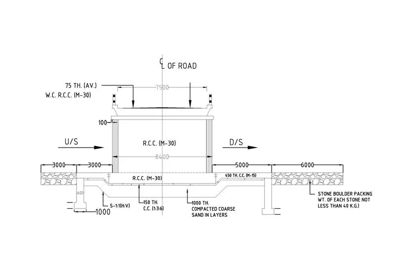
- An even simpler and relatively inexpensive solution to the scour problem is the use of concrete aprons around the piers and abutments of the bridge.
- RIP RAP
- This is a traditional method of erosion control for the shorelines. It is often the most economic means of repair and prevention.
- SHEET PILING
- Sheets can be provided to prevent scouring. The sheets provided up to the maximum scouring depth as per determined.
1C. What is uplift and how it can affect the foundation.
- Uplift pressure, which is also known as hydrostatic uplift, is an upward pressure applied to a structure that has the potential to raise it relative to its surroundings. It is the condition of greater pore water pressure than the overburden pressure of the structure.
-
The uplift pressure can be problematic if it is greater than the weight of the structure exerted downwards. IRC code, states that the upward pressure of water shall be taken as the full hydrostatic pressure applied over the entire area. The hydrostatic load shall be measured from the underside of construction.
-
The structure must be designed properly to provide greater resistance against uplift forces in order to prevent risks due to water pressure. So, the uplift pressure must be taken into consideration during design stage since rehabilitation and maintenance of foundation cannot be carried out easily in the future.
-
The possibility of occurrence of this upward force on foundation should be check when groundwater table is higher than the bottom of the foundation level. Due to the fact that hydraulic uplift pressure acts in upward direction. Therefore, it reduces the downward weight of the structure and consequently it acts against the stability of structure.
Effects of Uplift Pressure
- It reduces the effective weight of the structure.
- Endanger stability of the structure
Prevention for Uplift pressure
Dewatering procedure may help to control the water away from construction site, but it cannot keep the dewatering the whole life span of the construction as it is not an economical move. There are number of methods by which the influence of uplift pressure is avoided.
- Toeing in the foundation into the surrounding ground
- Increase self weigth of the structure
- Grond anchors
- Various type of piling to with stand the load
height 3,4,5 meters. with water level on top of ramp wall level .
Solution:
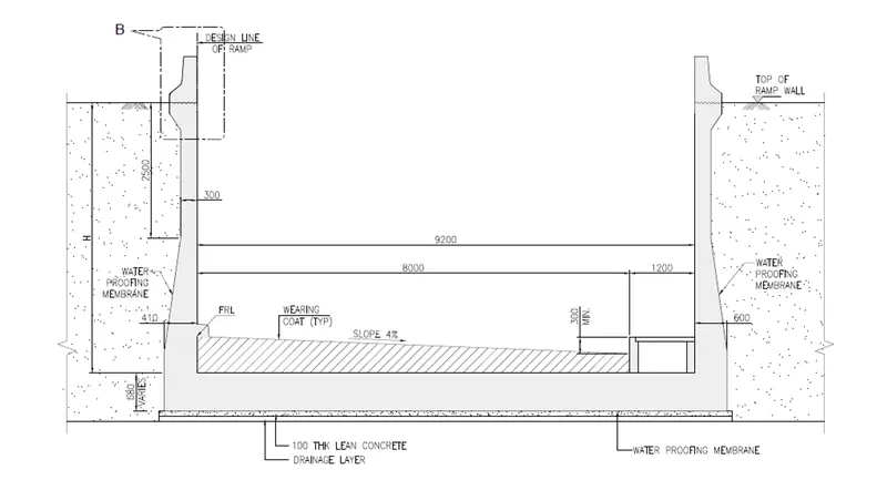
1. Force due to Uplift - (i)u = γwH (for 3 m height)
γw = Unit weight of water = 10 KN/m3
H = Height = in meters (m)
u = 10 x 3 = 30 kN/m2
(ii) u = γwH (for 4 m height)
u = 10 x 4 = 40 kN/m2
(iii) u = γwH (for 5 m height)
u = 10 x 5 = 50 kN/m2
What are different measures that can be taken to avoid uplift.
- Dewatering procedure may help to control the water away from construction site, but it cannot keep the dewatering the whole life span of the construction as it is not an economical move. There are number of methods by which the influence of uplift pressure is avoided.
1. Toeing in the Foundation into the Surrounding Ground
- When a substructure is built inside an open excavation or temporary cofferdam, the base slab or raft foundation can be extended outside perimeter to increase resistance to uplift.
- The weight of backfill material on the tied-in foundation increase the weight of the structure against uplift pressure. This method is not feasible where a diaphragm or secant pile wall is used as a permanent retaining structure.
2. Increase Self-weight of the Structure
- The self-weight of the building can be increased by increasing the size of structural members. sometime, the dead weight of the low-rise podium in a high-rise complex is increased by incorporating a rooftop garden with a thick soil fill.
3. Ground Anchors
- Pre-stressed anchors can be used as a temporary measure to counteract uplift forces. Permanent application of ground anchors is limited by concerns about their long-term performance with respect to corrosion.
4. Piling Method
- The piling method is the most effective method to resist Uplift pressure. Various types of piles are available to be used for countering uplift pressure based on soil condition and their necessity on site.
- For instance, end bearing pile, friction pile, un-reamed pile, sheet pile, tension pile, and compaction pile. Table 1 presents different types of piles used to contain uplift pressure based on soil conditions.