Week 3 Challenge
1.
Db = Deign descharge / Effective lenear waterway
=1000/128=7.8125
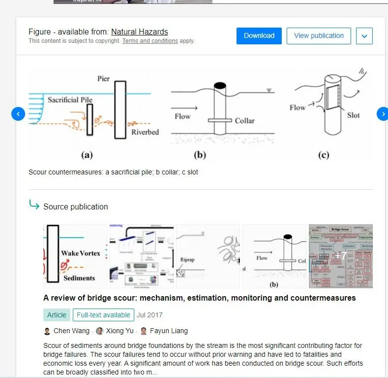
Means Score depth (dsm) 1.34*(db2/ksf)ke powar 0.33
=1.34*(7.8125)2/3)Ke power 0.33=3.62
Flood Without secimic zone condition
for pier =scour depth2x mean
2x3.62=7.2 Mtr
For Abutment
2xmean
2.362=7.2 mtr
Scour Depth = 2x mean (with Approch retsined or lowest bed level)
1.27*3.62=4.5974 m
2.
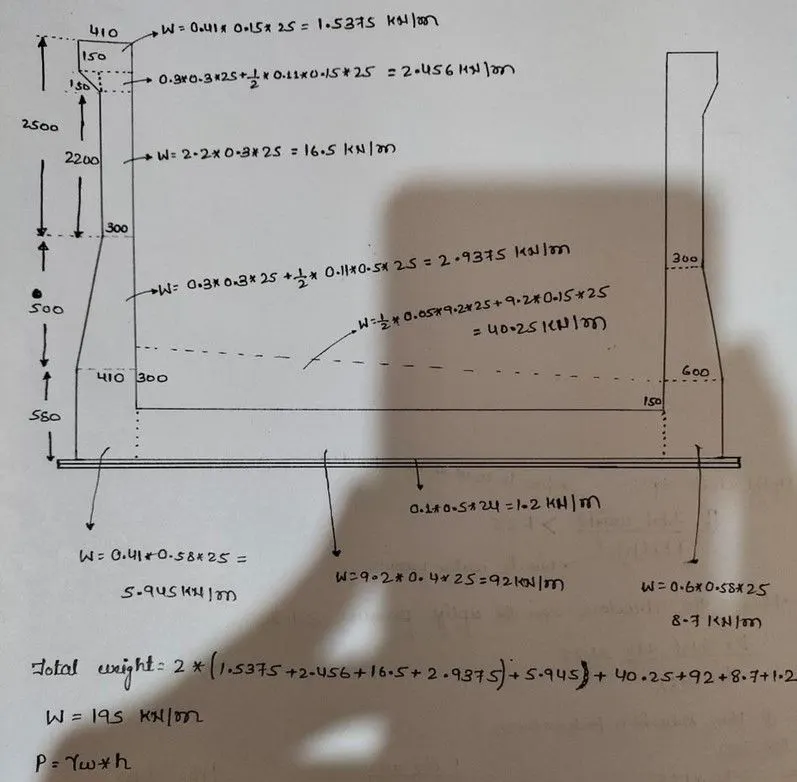
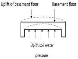
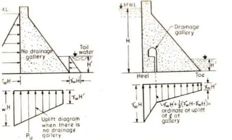
The weight of the substructure should be greater than uplift pressure in order to meet the requirements of applicable codes, i.e. summation of downward load per given area should be larger than that of the vertical load per given area.
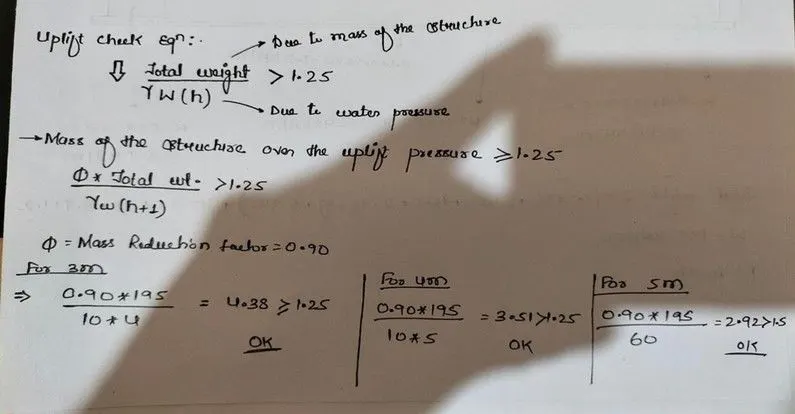
The downward load should at least greater than 25% compared to the upward load due to hydrostatic load. The following expression can be used to check the occurrence of uplift force below the structure under considerations:

where:
Ø: mass reduction factor, can be taken as 0.90
W: the mass of the structure
w: specific weight of water
h: height of water from the water table to the bottom of the foundation
1: Factor of safety
1. Toeing in the Foundation into the Surrounding Ground
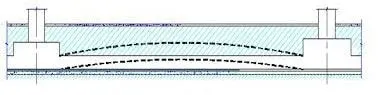
When a substructure is built inside an open excavation or temporary cofferdam, the base slab or raft foundation can be extended outside perimeter to increase resistance to uplift.
The weight of backfill material on the tied-in foundation increase the weight of the structure against uplift pressure. This method is not feasible where a diaphragm or secant pile wall is used as a permanent retaining structure.
2. Increase Self-weight of the Structure
The self-weight of the building can be increased by increasing the size of structural members. sometime, the dead weight of the low-rise podium in a high-rise complex is increased by incorporating a rooftop garden with a thick soil fill.
3. Ground Anchors
Pre-stressed anchors can be used as a temporary measure to counteract uplift forces. Permanent application of ground anchors is limited by concerns about their long-term performance with respect to corrosion.
4. Piling Method
The piling method is the most effective method to resist Uplift pressure. Various types of piles are available to be used for countering uplift pressure based on soil condition and their necessity on site.
For instance, end bearing pile, friction pile, un-reamed pile, sheet pile, tension pile, and compaction pile. Table 1 presents different types of piles used to contain uplift pressure based on soil conditions.
Table 1 Types of Piles Chosen Based on Soil Conditions to Withstand Uplift Pressure
| Types of Pile | Suitable Types of Soil |
| End bearing pile | Used when bedrock or rocklike material is present at a site within a reasonable depth. Piles are extended to the rock surface. The ultimate bearing capacity of the pile based on the underlying material. |
| Friction pile | It is used in cohesionless soil in which end bearing pile would be very long and uneconomical. The load on pile is resisted mainly by skin/friction resistance along the side of the pile. Capacity of the pile is a function of the shaft area in contact with the soil. Friction piles are often used to increase the density and thus the shear strength of soil. |
| Unreamed pile | It is used in black cotton soils, filled up ground and other types of soils having poor bearing capacity. |
| Sheet pile | Sheet piles, which made of thin plates of concrete; timber; or steel, driven into the ground for separating members or stopping seepage of water. it is not constructed for carrying any vertical load. |
| Tension pile | Tension piles uplift piles anchor down the structures subjected to uplift pressure. |
| Compaction pile | It is driven in loose granular soil. |
3.