Week 3 Challenge
1.1. State the primary load cases to be considered for design.
2. What is One – Way slab?
3. What is the value of unit weight of structural steel and soil?
4. Name few sections that can be defined using Properties tab in STAAD Pro.
5. Define Primary Beams.
1.1. State the primary load cases to be considered for design.
ANS:
- The primary load cases to be considered for design are:
a) Dead Load
b) Live Load/Imposed Load
c) Wind Load
d) Earthquake Load
e) Snow Load
1.2. What is One – Way slab?
ANS:
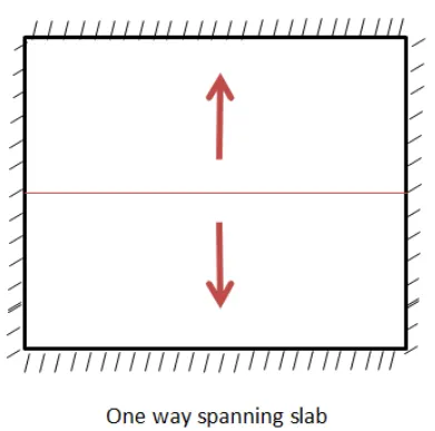
- If the ratio of Ly/Lx ( Ly = Longer direction , Lx = Shorter direction ) is greater than or equal to 2 , then we classify it as a One way slab
- Features of one way slab-
i) In one way slab bending is along in one direction only.
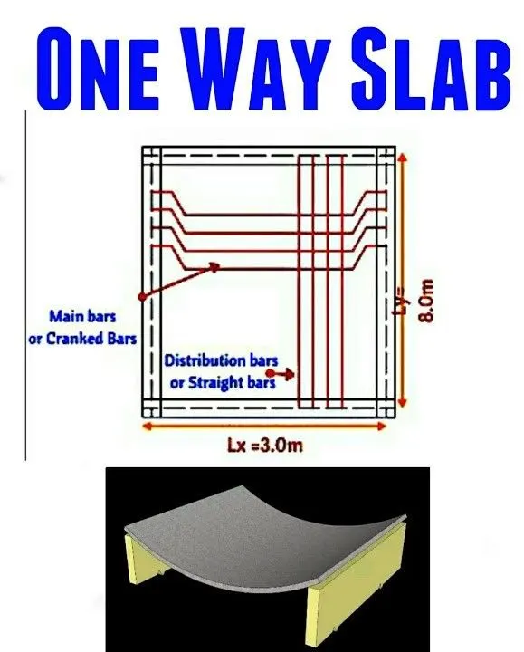
ii) In one way slab main reinforcement is provided along the shorter direction because when load is applied it will distributed quickly to the shorter span
iii) A distribution steel is provided to provide resistance against temperature and shrinkage .
iv) Eg of one way slab is Slab over the Toilets , Cantilever slab etc.
1.3. What is the value of unit weight of structural steel and soil?
ANS:
- The unit weight of a structural steel is 7850 kg/m^3
- The unit weight of soil is 18 kN/m^3
1.4. Name few sections that can be defined using Properties tab in STAAD Pro.
ANS:
- In staad pro we can define following sections to the model
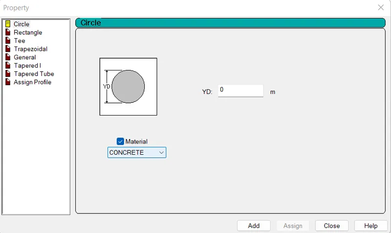
i) Circular section for columns
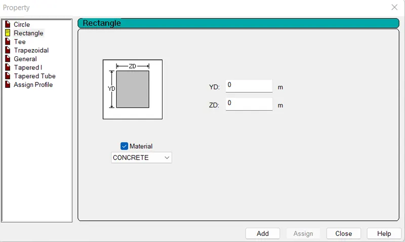
ii) Rectangular Sections for beams and column
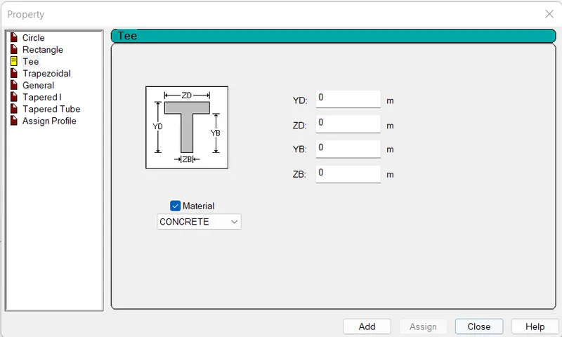
iii) Tee Section
iv) Trapezoidal section
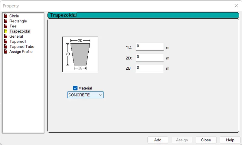
v) Tapered I section
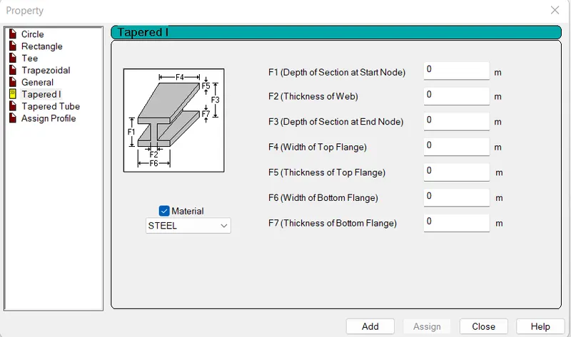
vi) Tapered Tube
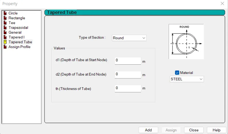
1.5. Define Primary Beams.
ANS:
- The beams that are connecting columns for transferring loads of a structure directly to the columns are known as primary beams.
- Usually, primary beams are shear-connected or simply supported , Fixed supported and they are provided in a regular building structure.
2.1. State the factors and parameters that influence the design pressure intensity of a high-rise building.
2. Mention the load transfer process of a Reinforced Concrete Building.
2.1. State the factors and parameters that influence the design pressure intensity of a high-rise building.
ANS:
- The factors and Parameters influence the design pressure Intensity as per IS 875 part 3
- The following factors and parameters that influence the design pressure intensity
1) Design wind speed -
Vz= Vb K1 K2 K3 K4
where ,
Vb=Basic wind speed (m/sec)
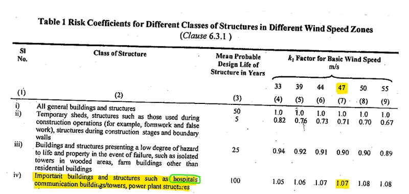
K1=Risk coefficient (Table 1 of IS 875 (Part 3)-2015)
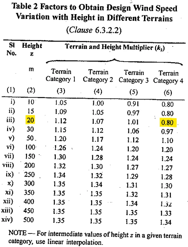
K2 = Terrain Roughness and height factor
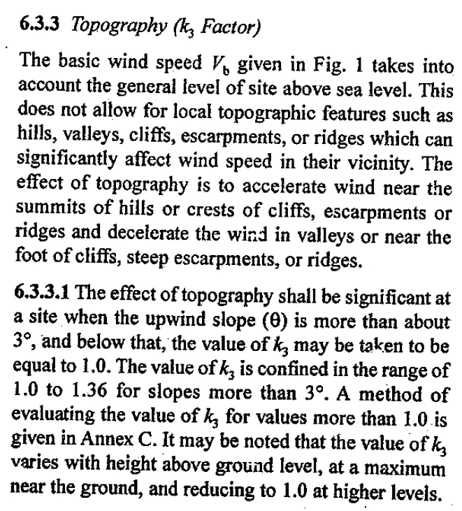
K3=Topography factor (Clause 6.3.3 of IS 875 (Part 3)-2015)
K4 =Importance factor for Cyclic Region
2) Design wind pressure (pd) -
pd= Kd Ka Kc pz
where
Kd= Wind directionality factor
Ka=area averaging factor
Kc = Combination factoras
3) The wind pressure pz at any height z is given by -
Pz= 0.6 Vz^2
where
Pz= Design Wind speed in N/m2 at height z
Vz= Design wind speed in m/s.
2.2. Mention the load transfer process of a Reinforced Concrete Building.
ANS:
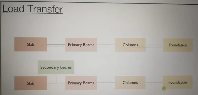
The load transfer process of a reinforced concrete building is the following-
i) Slab - The load will be transferred from Slab to Primary Beams
ii) Secondary beam - If Secondary beams are provided its load transferred to the Primary beams
iii) Primary beam - The loads from Primary beams to Columns
iv) Columns - The loads from Column to the Foundation
v) Foundation - Foundation transferred the load to the soil beneath the footing.
Here is the load transfered diagram mentioned below-
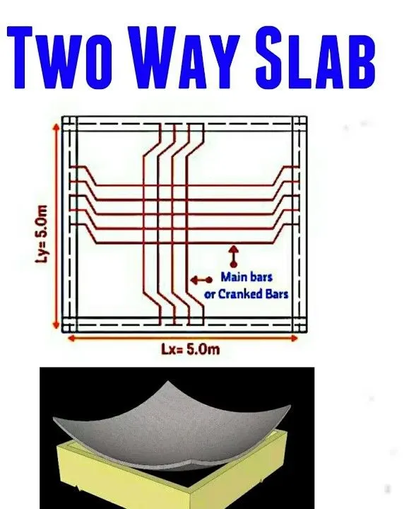
3.1. Differentiate One-Way and Two way slabs. Elaborate each slab type.
2. Explain the concept of secondary beams with proper sketch.
3. Mention the Primary load cases.
a. State the Indian Standards for each load case
b. Detail the parameters of each load case
c. Brief each load case
4. Detail the steps involved in assigning Properties and Support to a model using STAAD Pro sequentially.
5. Brief the steps to be followed to create and assign secondary beams in STAAD Pro
3.1. Differentiate One-Way and Two way slabs. Elaborate each slab type.
ANS:
|
One-Way slab |
Two way slab |
|
1) The one way slab is supported by a beam on two opposite side only. |
1) The two way slab is supported by the beam on all four sides. |
|
2) In one way slab, the load is carried in one direction perpendicular to the supporting beam. |
2) In two way slab, the load is carried in both directions. |
|
3) One way slab rest on two opposite side support beam/wall. |
3) Two Way Slab rest on four side beam /wall . |
|
4) One way slab is bend only in one spanning side direction while load transfer |
4) Two way slab is bend both spanning side direction while load transfer |
|
5) In One way slab the crank is provided in one direction |
5) In two-way slab, the crank is provided in four directions. |
|
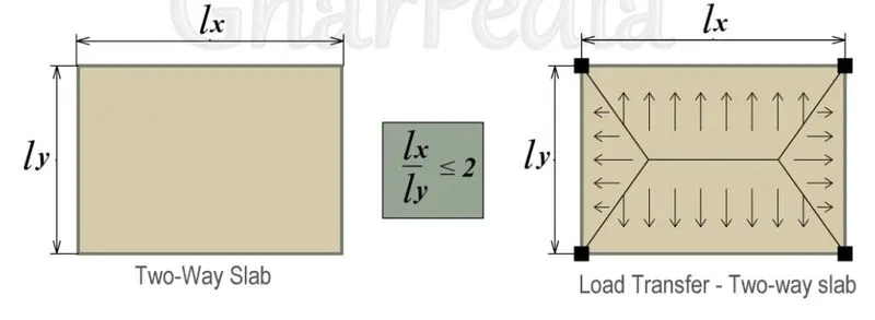
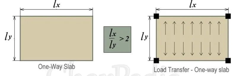
6) If (Length/bredth) ratio is greater than or equal 2 or then it is considered a one-way slab. i.e.(Lx/Ly)> 2 |
6) If Length/bredth the ratio is less than 2 then it is considered a two-way slab. i.e.(Lx/Ly)<= 2 |
|
7) The deflected shape of the one-way slab is cylindrical. |
7) Whereas the deflected shape of the two-way slab is a dish or saucer-like shape. |
|
8) Chajja and Varandha are practical examples of one-way slab. |
8) Whereas two-way slabs are used in constructive floors of the Multistorey building. |
|
9) In one-way slab quantity of steel is less. |
9) In two-way slab quantity of steel is more as compared to the one-way slab. |
|
Load Transfer:
|
 |
|
Rcc Detailing
|
|
3.2. Explain the concept of secondary beams with proper sketch.
ANS:
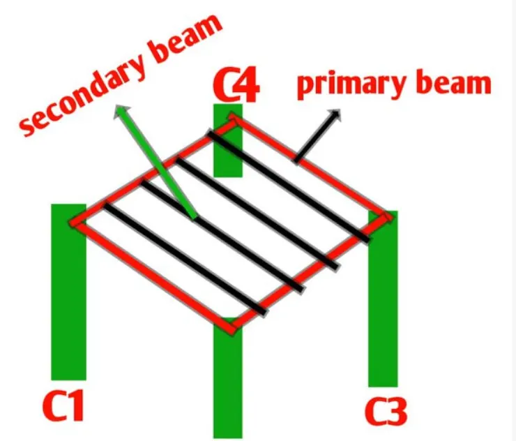
- From the above Sketch we can see that What is Primary beams and Secondary Beams
- Secondary beams are the beams which runs between primary beams or we can say that they rest on primary beams
- In normal case loads transferred will be Slabs - Primary beam - Columns - Foundation
- But Incase of Secondary beams , Primary beams carry the loads coming from Slab as well as Secondary beams i.e Slabs - Secondary Beams - Primary Beams - Columns - Foundations
- As the secondary beams are simply supported the moment will be developed at the support beacause The Secondary beams rest on simply supported condition.
- So therefore my secondary beams should get support from our primary beams with zero moment at the ends
- So therefore we have to give moment releases to the secondary beams.
3.3. Mention the Primary load cases.
a. State the Indian Standards for each load case
ANS:
i) Dead load - IS 875:1987 part 1.
ii) Super Imposed Dead Load - IS 875 part 1.
ii) Live Load - IS 875:1987 part 2.
iv) Seismic load - IS1893:2016 Part 1
v) snow load - IS 875:1987 part 4.
vi) Other load combination - IS 875:1987 part 5.
vii) Wind load - IS 875:1987 part 3.
b. Detail the parameters of each load case
ANS:
i) Dead load - a) Weight of structure
b) It remains constant
c) Volume of the section
ii) Super Imposed Dead Load - a) Floor Finishes
b) Service load
iii) Live Load - a) It is based on usage , occupancy etc .
b) building type residential building ,
c) commercial building
d) industrial building etc
iv) Seismic load: a) Anticipated earthquake's parameters at the site - known as seismic hazard
b) geotechnical parameters of the site
c) structures parameters
d) Characteristics of the anticipated gravity waves from Tsunami (if applicable).
v) Snow load: a) Snow Exposure Category
b) Snow Region
c) Ground snow load, Sg
d) Snow density. N
e) Average Recurrence interval
f) Balanced roof snow load, s
g) balanced Roof Snow Load
c. Brief each load case
ANS:
i) Dead Load - i) Dead load is generally considered as self weight of the structure .
ii) This loads are constant loads which are not going to change throught the life span of structure .
iii) DL of each structural member can be calculated by multiplying L x B x D X Density of concrete
ii) Live Loads - i) Live lods are not constant throughout the life span of structure
ii) It may vary depends upon usage , occupancy etc
iii) It may also vary depends upon the type of building such as residential , commerecial , Industrical etc
iv) For Residential Builidig we assumen LL as 3KN/m^2
iv) Seismic load: i)Seismic load indicates how much seismic energy (waves of energy that travel through the earth) a structure would need to endure in a specific geographic location
ii)Seismic loading means application of an earthquake-generated excitation on a structure (or geo-structure). It happens at contact surfaces of a structure either with the ground, with adjacent structures, or with gravity waves from tsunami. It is related to the seismic hazard of the location
iii) It may also vary depends upon the type of strata, geotechnical conditions, hazard intensity, gravity waves , structure parameters etc
3.4. Detail the steps involved in assigning Properties and Support to a model using STAAD Pro sequentially.
ANS:
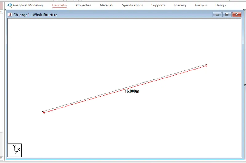
AIM: To Draw fixed beam span 16m with
TOOL AND COMMAND:
- Geometry
- Property
- Supprots
PROCEDURE:
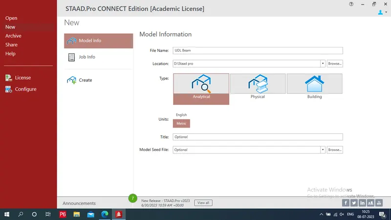
Step 1: Open Staad pro:
- First open the staad.pro software and fill all the project details and select unit system as Metric.
- Then select the model as analytical.
Step 2: To Draw Geometry:
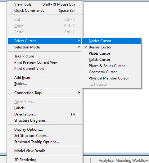
- Right click - select cursor - and choose nodes cursor
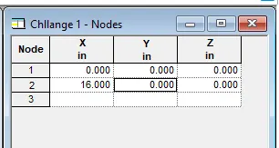
- Click on nodes tab in 1,X and put value (0,0,0) and (16,0,0)
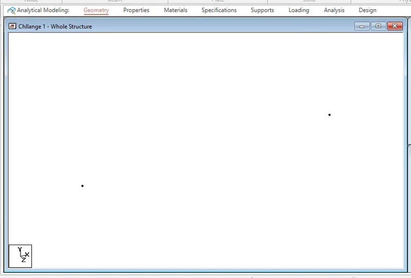
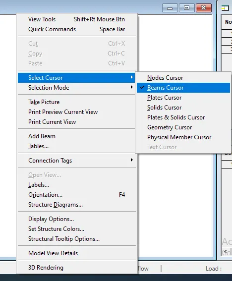
- For Draw beam- Right click - select cursor - and choose beam cursor
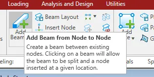
- Select add beam from geomerty tab
- Join these two nodes
Step 3: To Apply Properties:
- Click on properties tab which is 2nd stage
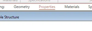
- Click on define
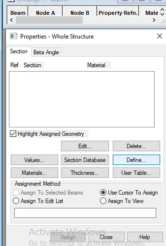
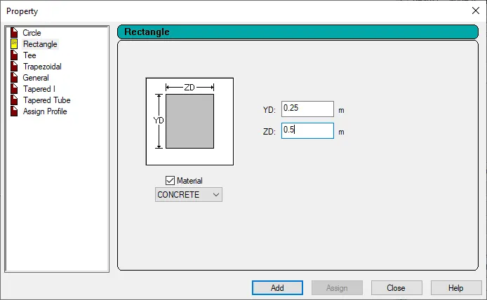
- Select rectangle and provide its depth and breadth my beam size is 250 x500
- Choose material as concrete b/c it is rcc beam - Add it by clicking on add - close tab
- Select section provide assignment method as "assign to view" - assign - yes
- Properties are assign to beam
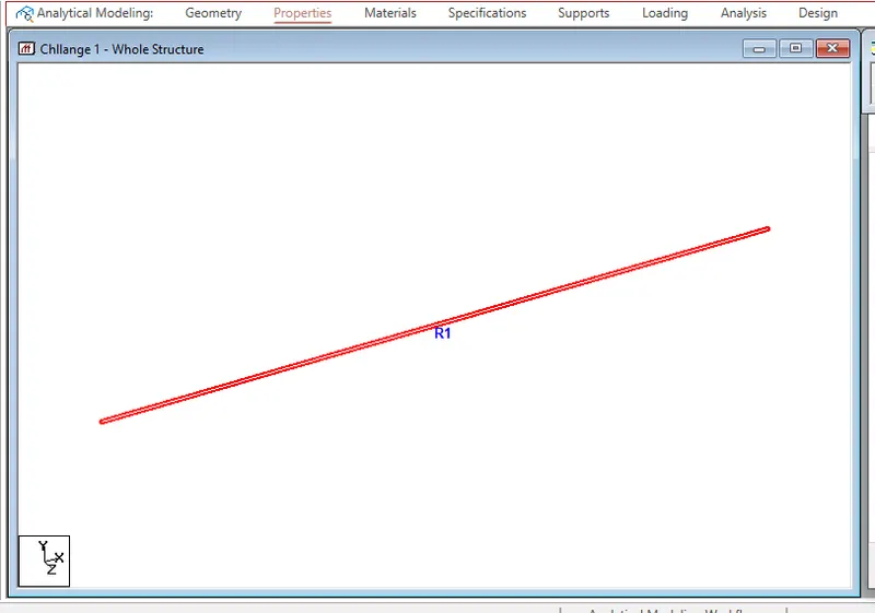
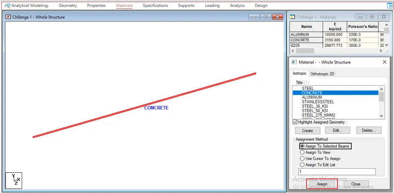
Step 4: To Apply material:
- Go to material tab - select concrete - Assign to view - assign - yes
- Material is assign to beam
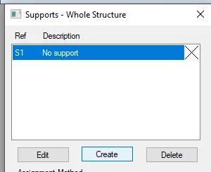
Step 5: To provide Supprots:
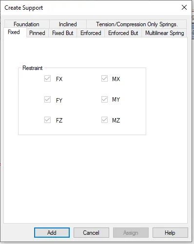
- Go to next tab as a Supports Click on create
- Provide fixed support - Add - Close
- Then assign them to the drawing by using "use cursor to assign" - assign .
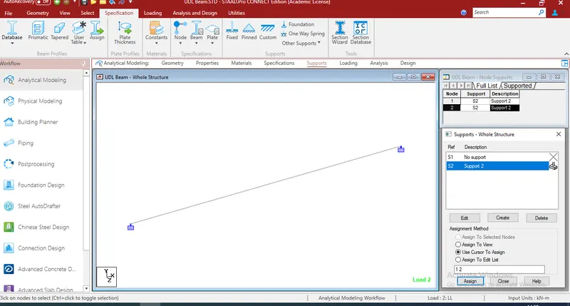
RESULT: Describe the steps to assigning Properties and Support to a model
3.5. Brief the steps to be followed to create and assign secondary beams in STAAD Pro
AIM:
To Draw displacement, SFD and BMD for fixed beam span 16m with UDL load 9kN
TOOL AND COMMAND:
- Geometry
- Property
- Loading
- Supprots
- Analysis
- Design
- Run analysis
- Analysis command
- Command file
- Annotate
- Displacement,Fy,Mz
PROCEDURE:
Step 1: Open Staad pro:
- First open the staad.pro software and fill all the project details and select unit system as Metric.
- Then select the model as analytical.
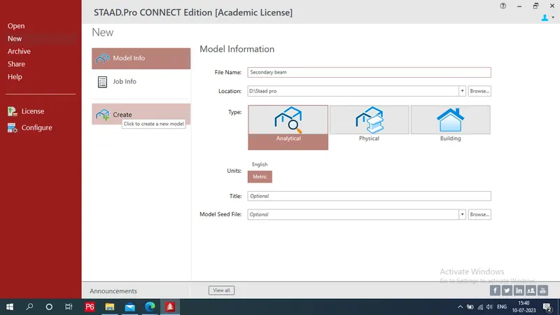
Step 2: To Draw Geometry:
a) To Draw Primary beams and columns:
- Right click - select cursor - and choose nodes cursor
- Click on nodes tab in 1,X and put value (0,0,0) and (5,0,0)
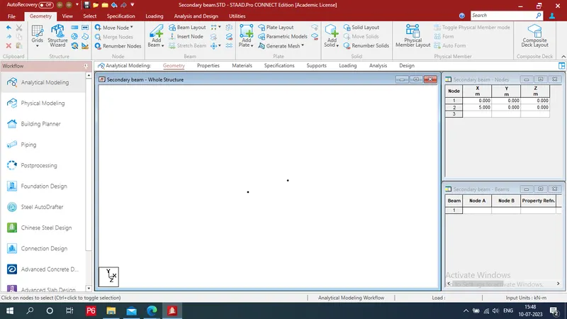
- Select these both nodes press ctrl+c => ctrl+v for making copy and paste
- Put z= 8 - ok
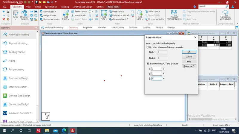
- We get a 4 nodes
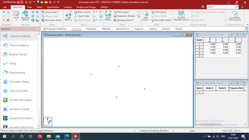
-By using Translational Repeat commnad from geometry tab in structure section
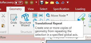
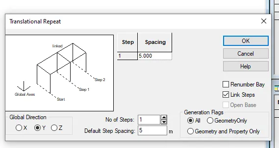
- Provide Gloabal direction: Y , step No:1, Default step spacing:5, Check box of Link steps - ok
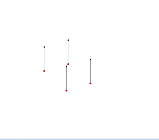
- For Draw beam- Right click - select cursor - and choose beam cursor
- Select add beam from geomerty tab
- Join these top 4 nodes drawn by beams
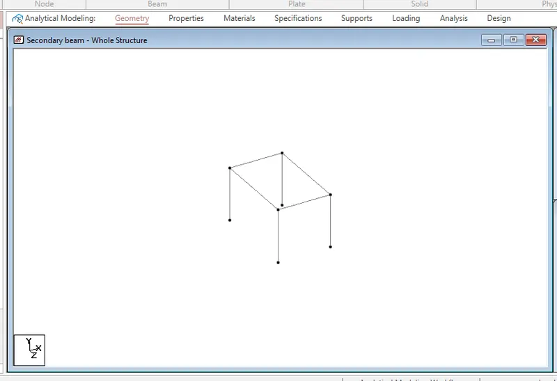
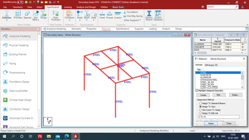
b) To Draw Secondary beams :
- Againg select add beams - mid point
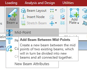
- Draw 2 secondary beam at cenetre
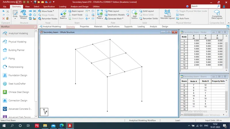
Step 3: To Apply Properties:
- Click on properties tab which is 2nd stage
- Click on define
- Select rectangle and provide its depth and breadth my beam size is 230 x300
- Choose material as concrete b/c it is rcc beam - Add it by clicking on add - close tab
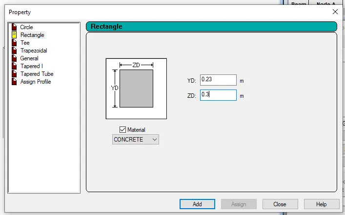
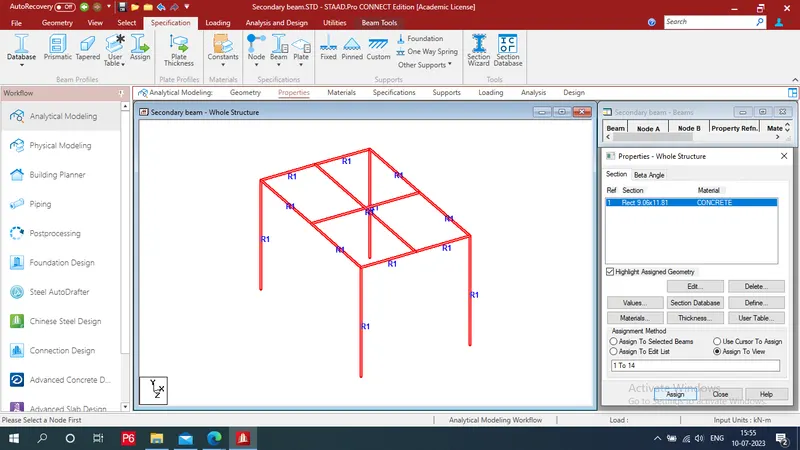
- Select section provide assignment method as "assign to view" - assign - yes
- Properties are assign to beam
Step 4: To Apply material:
- Go to material tab - select concrete - Assign to view - assign - yes
- Material is assign to beam
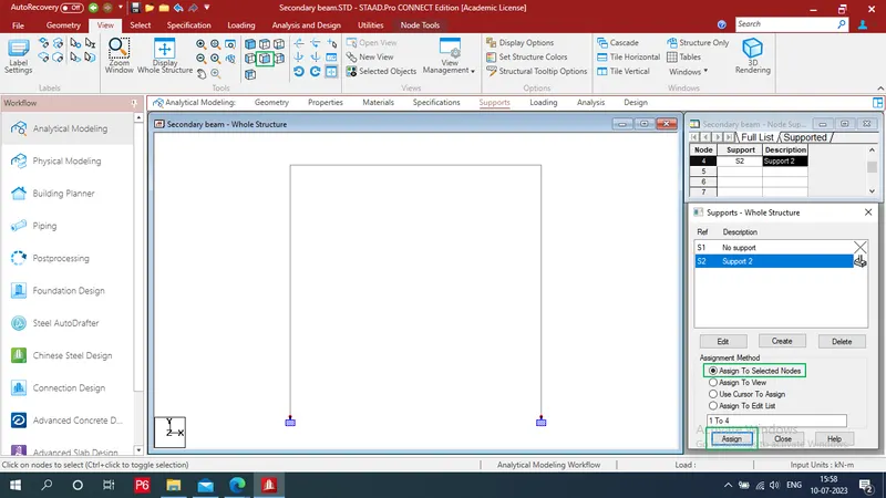
Step 5: To provide Supprots:
- Go to next tab as a Supports Click on create
- Provide fixed support - Add - Close
- Go to view tab select front (5th) view
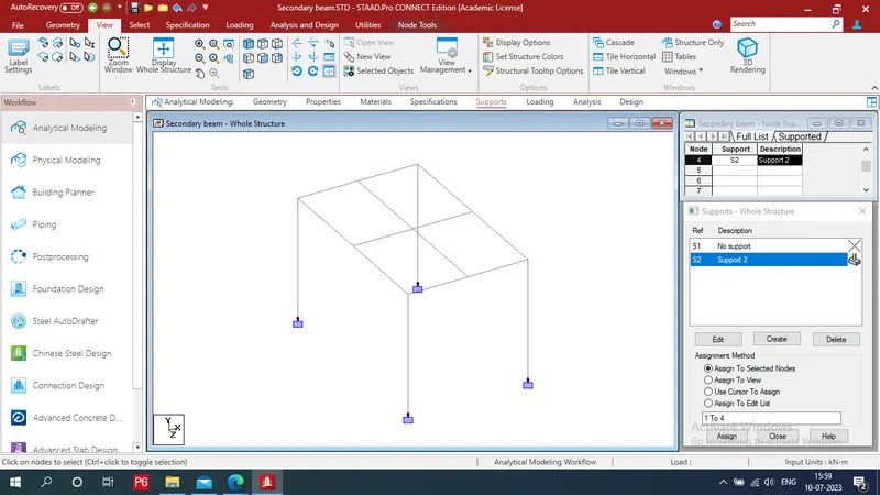
- Then assign them to the drawing by using "use cursor to assign" - select bottom nodes- assign .
- Click on 3D view
Step 6: To Provide specification:
- For provide specification to seconadary beams to released the reactions and moments
- Select Beam in sepecification whole structure tab
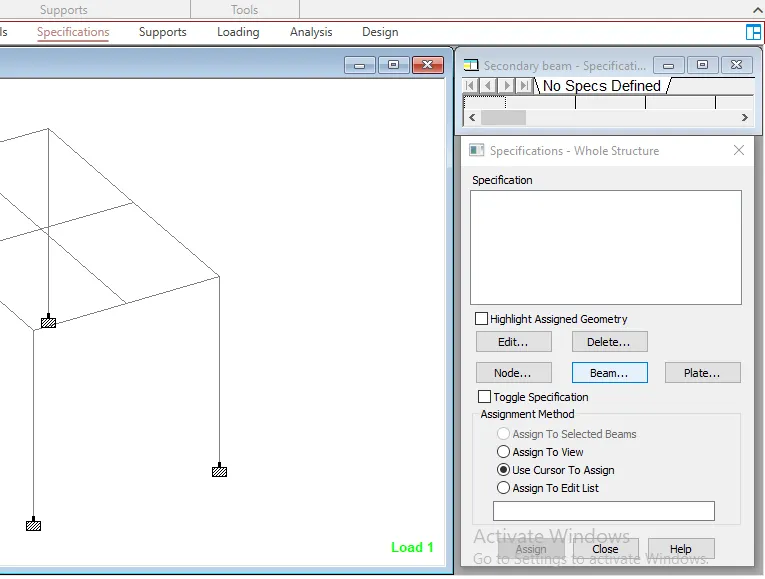
- Select its loacation as start and provide release reaction as Fx and moment as Mz - Add
- Select its loacation as End and provide release reaction as Fx and moment as Mz - Add - Close
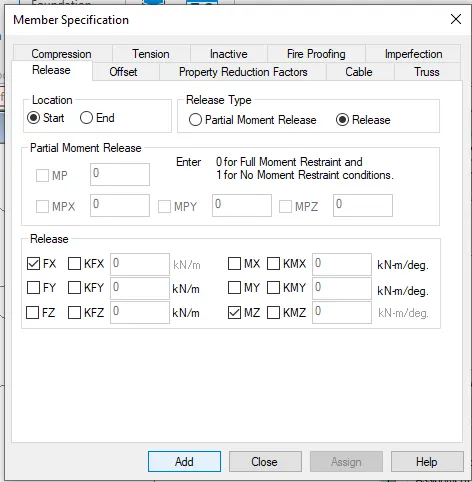
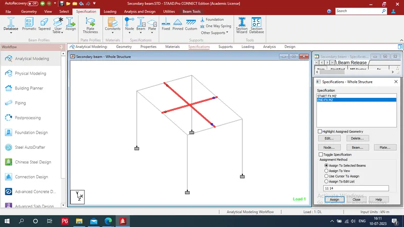
- Select start Fx Mz - select secondary beams - assign - yes
- Repeat this procedure for End Fx Mz
Step 7: To Apply Loading:
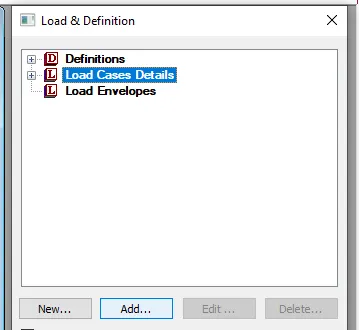
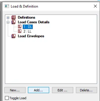
- Go to loading tab select "load cases deatils" - add
- Provide priamry load cases as DL And LL
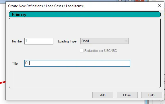
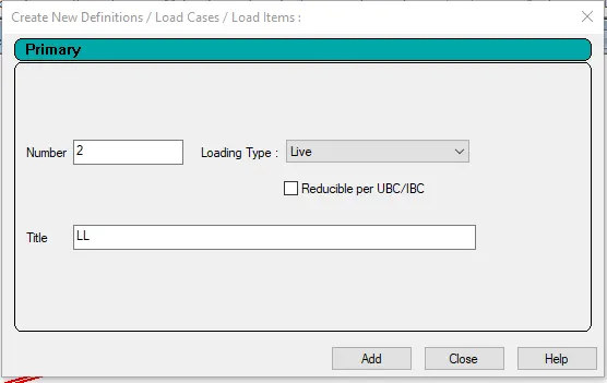
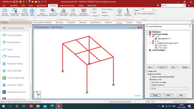
- Select DL And Click on add - provide self weight as -1KN - add
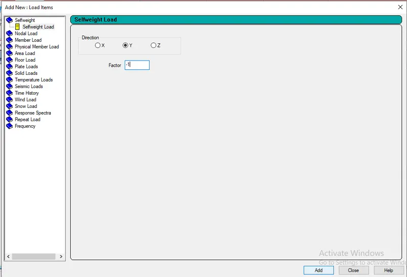
- Repeate this procedure for LL And put Member load -3 kN
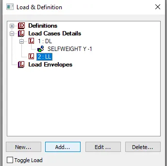
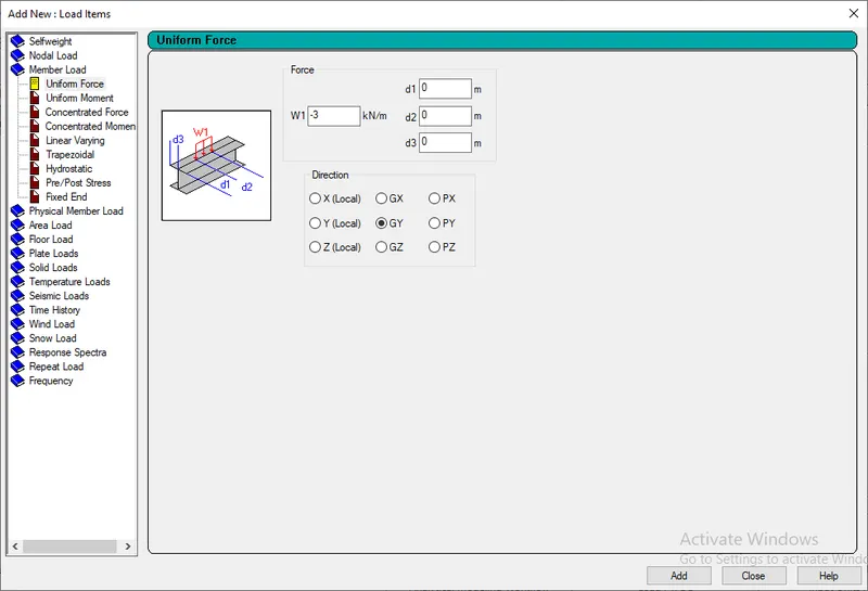
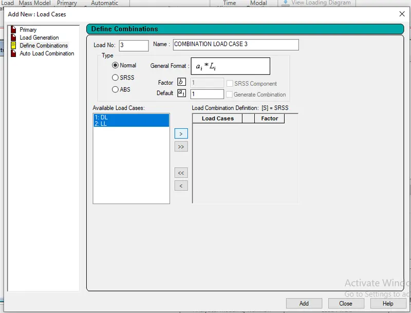
- Add load combination - Load case details - add - Define combination
- Select both loads - click on >
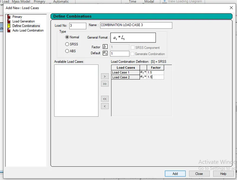
- Provide factors as 1.5 for both - add
- Self weight is aasign to view
- For applying LL: select UNI GY -3KN/M
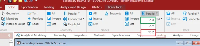
- Go to select tab - click on parallel from beam section - select "TO X + CTRL + TO Z"
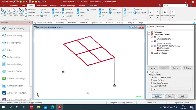
- Select assignment method is "Assign to selected beams" - assign - yes
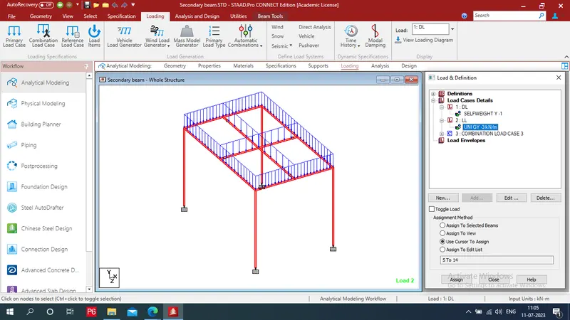
- Both loads are applied
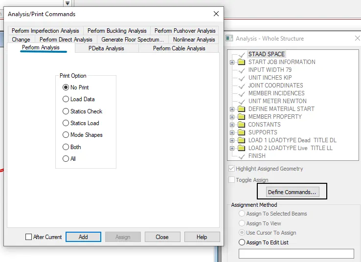
Step 8: Do Analysis:
- After going to analysis tab "Define command" - select perform analysis - add - close
- From utilities tab click on Command file
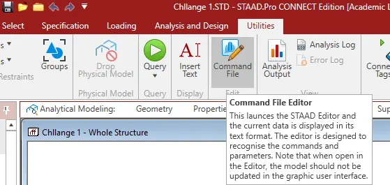
- Click on staad plane and change staad space name to staad plane close it and Save it
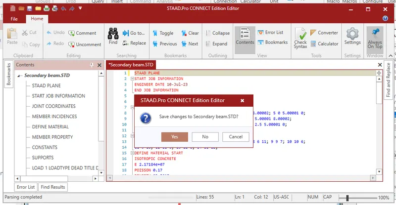
Step 9: Design by run analysis :
- Select material type
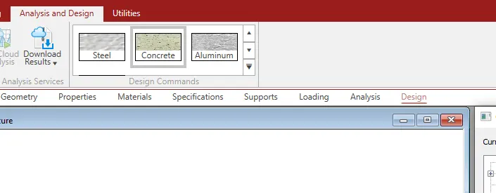
- Go to design Define parameters as Compressive strength of concrete and yeild strength of steel
- Select IS456 as a current code
- Assign it by method of assign to view - assign

- Run analysis from analysis and design tab
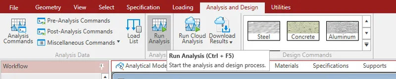
- Click on Go to post processing mode - Done
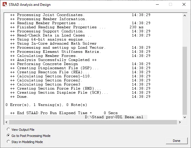
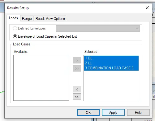
- Select loads - > - Apply - Ok
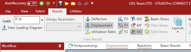
- We get a result
Step 10: Displacement, SFD And BMD:
- Click on displacement, MZ we get BMD and click on FY we get sfd
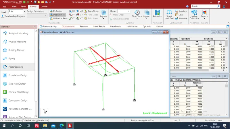
Displacement
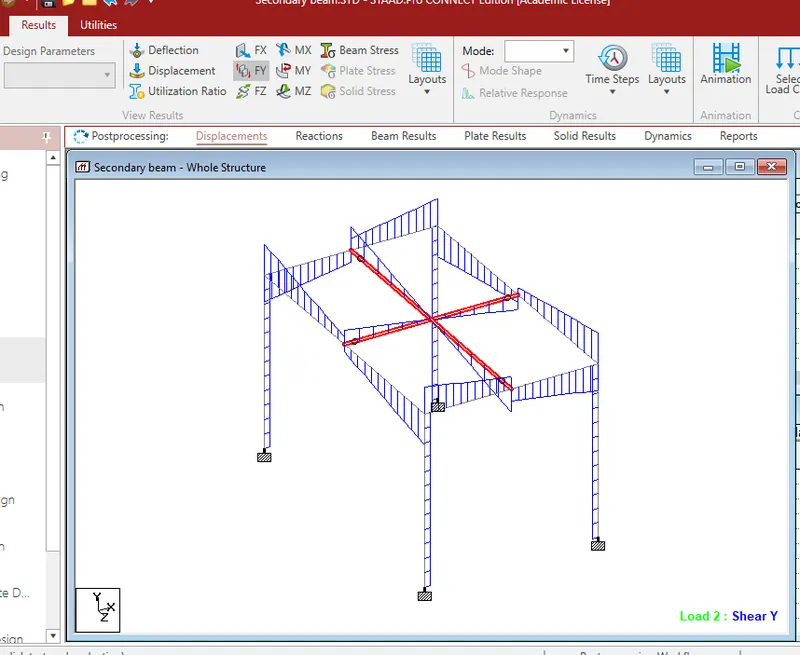
SFD
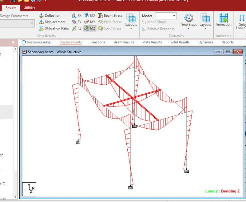
BMD
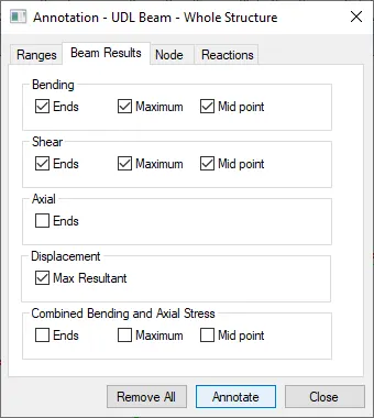
- From result tab choose annotate

- Check box as per requirement here i am choosing end and max for Bending and shear - Annotate - close
RESULTS: Draw displacement, Sfd and Bmd for secondary beam with fixed support
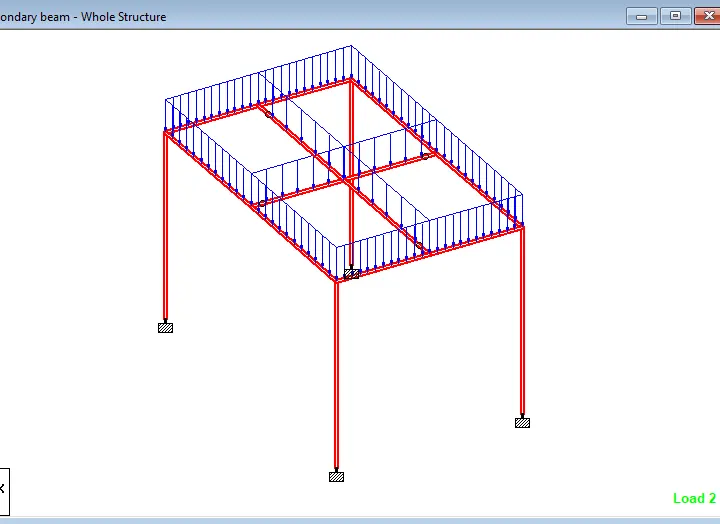
Beam
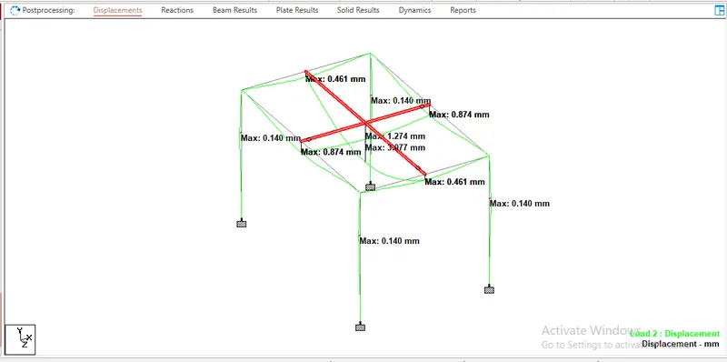
Displacement
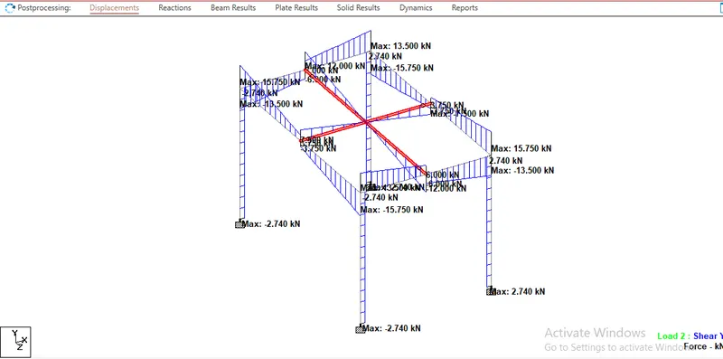
SFD
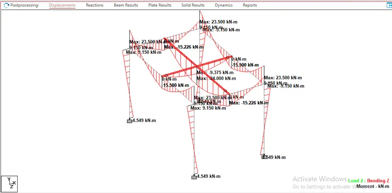
BMD
Practical
1. Calculate the wind pressure for the given building
a. Building Dimension : 20m x 30m x 20m height RCC
b. Building usage : Hospital block in city centre
c. Location : Darjeeling
AIM:- To calculate the wind pressure of a 20m hight Reinforced cement concrete building located in Darjeeling
TOOL AND COMMAND:
- I calculted live by using IS 875 (Part 3)-2015
PROCEDURE:-
STEP-1:- Calculattion for Design Wind Speed:-
We know that
i) Vz = Vb x k1 x k2 x k3 x k4
where ,
Vb=Basic wind speed (m/sec)
K1=Risk coefficient (Table 1 of IS 875 (Part 3)-2015)
K2 = Terrain Roughness and height factor
K3=Topography factor (Clause 6.3.3 of IS 875 (Part 3)-2015)
K4 =Importance factor for Cyclic Region
AS Vb = 47 m/s ( Darjeeling ) Is 875 Annexure A
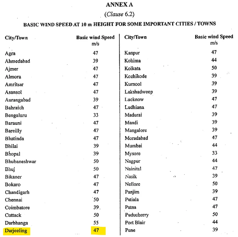
K1 = 1.07 (given in Table 1 of IS-875 part 3)
K2 = 0.80 ( Ht for 20m) (Category 4 as building is located in city center)
K3 = 1 [Topography factor (Clause 6.3.3 of IS 875 (Part 3)-2015)]
K4 = 1 [Clause 6.3.4 of IS 875 (Part 3)-2015] As this zone does not falls under cyclone zone
Therefore ,
Vz = 47 x 1.07 x 0.80 x 1 x 1
= 40.23 m/s
ii) Wind Pressure = Pz
We know that
Pz = 0.6 x Vz ^2
= 0.6 x 40.23 x 40.23
= 971.168 N
= 0.97 Kn
RESULT:- Calculate wind ressure by using above formula, Similarly we can calculate for different heights
| Height (m) | k2 | Vz (m/s) | Pz | Pz in kN |
| 3.5 | 0.80 | 40.232 | 971.17 | 0.97 |
| 6.5 | 0.80 | 40.232 | 971.17 | 0.97 |
| 9.5 | 0.80 | 40.232 | 971.17 | 0.97 |
| 12.5 | 0.80 | 40.232 | 971.17 | 0.97 |
| 15.5 | 0.80 | 40.232 | 971.17 | 0.97 |
| 18.5 | 0.80 | 40.232 | 971.17 | 0.97 |
| 20 | 0.80 | 40.232 | 971.17 | 0.97 |
Practical-
2. Calculate the Dead load and Live load for the above building with reference to IS standards ( assume suitable sections )
Ans=
AIM:- To calculate the dead load and live load of a 20m x 30m x 20m hight Reinforced cement concrete building located in Darjeeling.
TOOL AND COMMAND:
- I calculted live by using IS875 part 2
PROCEDURE:-
STEP-1:- To Calculate Dead Load of Column , Beam , Wall and Slab are as follows -
A) For Column -
i) As we have assume Column Size as (0.5 x 0.5 )
ii) Length of column = 20m (upto roof level)
Therefore,
Dead Load = L X B X H x Unit weight of Concrete
= 20 x 0.5 x 0.5 x 25
= 125 KN
So Dead Load of Each Column is 125 KN
2) For Beams -
i) As we have assume Beams Size as ( 0.300 x 0.50 m)
Hence,
Dead Load = B X H x Unit weight of concrete
= 0.3 x 0.5 x 25
= 3.75 KN/m
So Dead Load of Beam is 3.75 KN/m
3) For wall - As it has Block
i) Assume the Height of wall 3 m
ii) Thickness of wall = 0.230 m
iii) Unit weight of Blocks = 20Kn/m^3
Therefore,
Dead Load = B X H x unit weight of block
= 0.230 x 3 x 20
= 13.8 KN / m
So Dead Load of wall is 13.8 KN /m
4) For Slab
i) Assume the thickness of slab = 200 mm
Hence
Dead Load = thickness X Unit weight of concrete
= 0.200 x 25
= 5 KN / m^2
Dead Load of Slab = 5 Kn/m^2
Step-2: For Live Load - As per IS 875 Part 2
|
Sl. No. |
Description |
UDL Load (kN/m2) |
Concentrated Load (kN) |
|
1. |
Bathrooms and toilets in all types of buildings |
2 |
1.8 |
|
3 |
Office rooms in |
||
|
(i)Hostel, hotels, hospitals and business building with separate store |
2.5 |
2.7 |
|
|
(ii)In assembly buildings |
3 |
4.5 |
|
|
4. |
Kitchens in |
||
|
(i) Dwelling houses |
2 |
1.8 |
|
|
(ii) Hostels, hotels and hospitals |
3 |
4.5 |
|
|
5. |
Banking halls, class rooms, X-ray rooms, operation rooms |
3 |
4.5 |
|
6. |
Dining rooms in |
||
|
(i)Educational buildings, institutional and mercantile buildings |
3 |
2.7 |
|
|
(ii)Hostels and hotels |
4 |
2.7 |
|
|
7. |
Corridors, passages, stair cases in |
||
|
(i) Dwelling houses, hotels, and hostels |
3 |
4.5 |
|
|
(ii)Educational, institutional and assembly buildings |
4 |
4.5 |
|
|
(iii) Mercantile buildings |
5 |
4.5 |
|
|
8. |
Reading rooms in libraries |
||
|
(i)With separate storage |
3 |
4.5 |
|
|
(ii)Without separate storage |
4 |
4.5 |
|
|
9. |
Assembly areas in assembly buildings |
||
|
(i)With fixed seats |
5 |
||
|
(ii)Without fixed seats |
5 |
3.6 |
|
|
10. |
Store rooms in educational buildings |
5 |
4.5 |
|
11. |
Store room in libraries |
6 for a height of 2.24 2kN/m2 for every 1m additional height |
4.5 |
|
12. |
Boiler rooms and plant rooms in |
||
|
(i)Hostels, hotels and hospitals, mercantile and industrial buildings |
5 |
4.5 |
|
|
(ii)Assembly and storage buildings |
7.5 |
4.5 |
RESULT:-
All the dead and live loads are shown as per given question.