Creation of geometries by Coordinate system methods using AutoCad
A) AIM :
- Create the geometries from P1 to P2 using all the coordinates system methods. These are following:
-
Types of coordinate system is given below :
i) Absolute coordinate system
ii) Relative rectangular system
iii) Relative polar coordinate system
iv) Direct distance entry method
- By using the Line tool to create the geometries. Use the circle tool in some cases .
SOFTWARE USED : Autodesk autocad 2021
B) PROCEDURE :
- First, open the AutoCAD software give command the software QNEW or go to the application menu and click the NEW option then click on ADVANCE SETTING.
- Select matric setting : unit in decimal having precision 0.0
- template: Acad.dwg
- Angle : Decimal degree
- Angle measure : East (clockwise direction)
- Select the area 10*10
- Click on finished option.
C) EXAMPLES:
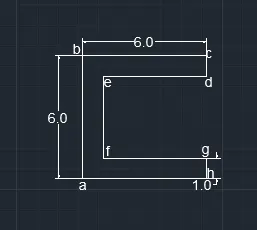
EXAMPLE : 1
PROCEDURE :
i) ABSOLUTE COORDINATE SYSTEM :
(Ensure that the Dynamic input bottom is not choosen)
- Give the line command to the autocad software
- Lines specify first point =2,1 i.e. starting point a
- Specify next point, b=2,7
- Specify next point, c=8,7
- Specify next point, d=8,6
- Specify next point, e=3,6
- Specify next point, f=3,2
- Specify next point, g=8,2
- Specify next point, h=8,1
- then closed. By giving command c > Enter
ii) RELATIVE RECTANGULAR COORDINATES :
- Now, choose line command
- Specify first point, a=2,1 that is starting point
- Specify next point, b=@0,6 i.e dx:0 units dy: 6 units
- Specify next point, c=@6,0 i.e dx: 6 units dy: 0 units
- Specify next point, d=@0,-1 i.e dx:0 units dy:-1 units
- Specify next point, e=@-5,0 i.e dx:-5 units dy:0 units
- Specify next point, f=@ 0,-4 i.e dx :0 units dy : -4 units
- Specify next point, g=@5,0 i.e dx: 5 units dy : 0 units
- Specify next point, h =@0,-1 i.e dx: 0 units dy :-1 units
- Closed. By giving command c > Enter
iii) RELATIVE POLAR COORDINATES :
- line command
- a=2,1 starting point
- b=@6<90
- c=@6<0
- d=@1<270
- e=@5<180
- f=@4<270
- g=@5<0
- h=@1<270
- then closed. C > Enter
iv) DIRECT DISTANCE ENTRY :
- Line command
- 6 cursor facing to north direction
- 6 cursor facing to east direction
- 1 cursor facing to south direction
- 5 cursor facing to west direction
- 4 cursor facing to south direction
- 5 cursor facing to east directon
- 1 cursor facing to south direction
- closed . By giving command c > Enter
- RESULT :
EXAMPLE :2
PROCEDURE :
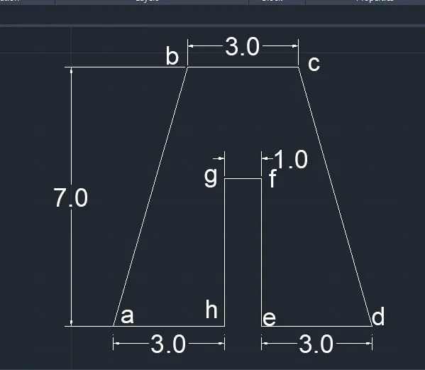
i) ABSOLUTE COORDINATE SYSTEM :
- Give line command
- Specify first point, a= 2,1 starting point
- Specify next point, b=2,8
- Specify next point, c=7,8
- Specify next point, d=9,1
- Specify next point, e=6,1
- Specify next point, f=6,5
- Specify next point, g=5,5
- Specify next point, h=5,1
- closed. By giving command c > Enter
ii) RELATIVE RECTANGULAR COORDINATE :
- line command
- Specify first point, a=2,1 starting point
- Specify next point, b=@2,7 i.e dx:2 units dy :7 units
- Specify next point, c=@3,0 i.e dx: 3 units dy :0 units
- Specify next point, d=@2,-7 i.e dx:2 units dy:-7 units
- Specify next point, e=@-3,0 i.e dx:-3 units dy:0 units
- Specify next point, f=@0,4 i.e dx:0 units dy:4 units
- Specify next point, g=@-1,0 i.e dx:-1 units dy:0 units
- Specify next point, h=@ 0,-4 i.e dx:0 units dy:-4 units
- Closed. By giving command c > Enter
iii) RELATIVE POLAR COORDINATES :
- Choose Line command
- Put, a=2,1 starting points
- @7<90 (line one )
- @2<0 (line two )
- Then joined the points and get b point
- Delete line one and line two
- c=@3<0
- @7<270 (line three)
- @2<0 (line four)
- Joint the endpoint of line c and line four and get point d
- Delete line three and four
- e=@3<180
- f=@4<90
- g=@1<180
- h=@4<270
- Closed. By giving command c > Enter
iv) DIRECT DISTENCE ENTRY :
- Give the line command
- 7 upward (line a to #)
- 2 right direction (line # to b )
- joint point c and b
- delete line a to # and # to b
- 3 right direction (b to c)
- 7 downward direction (line c to #)
- 2 right directon (line # to d)
- join the point c and d
- delete the line c to # and # to d
- 3 left direction (line d to e)
- 4 upward direction ( line e to f )
- 1 left direction (line f to g)
- 4 downward direction (g to h)
- Then closed . By giving command c > Enter
- RESULTS :
EXAMPLE :3
PROCEDURE :
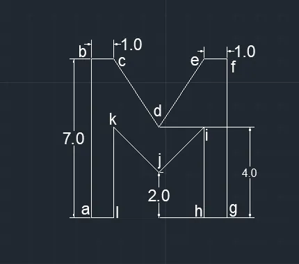
i) ABSOLUTE COORDINATE SYSTEM :
- Give the line command after that enter first point.
- Specify first point,a= 2,1 starting points
- Specify next point, b=2,8
- Specify next point, c=3,8
- Specify next point, d=5,5
- Specify next point, e=7,8
- Specify next point, f=8,8
- Specify next point, g=8,1
- Specify next point, h=7,1
- Specify next point, i=7,5
- Specify next point, j=5,3
- Specify next point, k=3,5
- Specify next point, l=3,1
- closed. By giving command c > Enter
ii) RELATIVE RECTANGULAR COORDINATE :
- line command
- Specify first point, a=2,1 starting points
- Specify next point, b=0,7 i.e dx:0 units and dy:7 units
- Specify next point, c=1,0 i.e dx:1 units and dy: 0 units
- Specify next point, d=2,-3 i.e dx:2 units and dy:-3 units
- Specify next point, e=2,3 i.e dx:2 units and dy: 3 units
- Specify next point, f=1,0 i.e dx:1 units and dy:0 units
- Specify next point, g=0,-7 i.e dx:0 units and dy:-7 units
- Specify next point, h=-1,0 i.e dx:-1 units and dy:0 units
- Specify next point, i=0,4 i.e dx:0 units and dy:4 units
- Specify next point, j=-2,-2 i,e dx:-2 units and dy :-2 units
- Specify next point, k=-2,2 i.e dx:-2 units and dy :2 units
- Specify next point, l=0,-4 i.e dx:o units and dy :-4 units
- then closed. By giving command c > Enter
- RESULTS :
EXAMPLE :4
PROCEDURE :
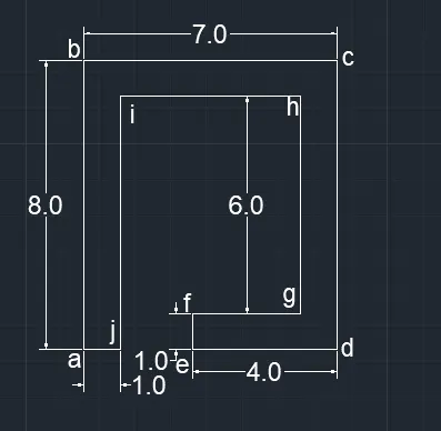
i) ABSOLUTE COORDINATE METHOD :
- Line command
- Specify first point,a=2,1 starting points
- Specify next point, b=2,9
- Specify next point, c=9,9
- Specify next point, d=9,1
- Specify next point, e=5,1
- Specify next point, f=5,2
- Specify next point, g=8,2
- Specify next point, h=8,8
- Specify next point, i=3,8
- Specify next point, j=3,1
- then closed. By giving command c > Enter
ii) RELATIVE RECTANGULAR COORDINATE :
- Give line command
- Specify first point, a=2,1 starting points
- Specify next point, b=@0,8 i.e dx:0 units and dy:8 units
- Specify next point, c=@7,0 i.e dx;7 units and dy:0 units
- Specify next point, d=@0,-8 i.e dx:0 units and dy:-8 units
- Specify next point, e=@-4,0 i.e dx:-4 units and dy:0 units
- Specify next point, f =@0,1 i.e dx:0 units and dy:1 units
- Specify next point, g=@4,0 i.e dx: 4 units and dy:0 units
- Specify next point, h =@0,6 i.e dx:0 units and dy:6 units
- Specify next point, i=@-5,0 i.e dx:-5 units and dy:0 units
- Specify next point, j=@0,-7 i.e dx:0 units and dy:-7 units
- then closed . By giving command c > Enter
- RESULTS :
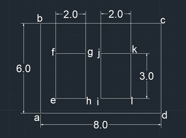
EXAMPLE : 5
PROCEDURE :
i) ABSOLUTE COORDINATE SYSTEM:
- give the line command to autocad
- Specify first point, a=2,1 that is starting point
- Specify next point, b=2,7
- Specify next point, c=10,7
- Specify next point, d=10,1
- closed
- Again, give line command
- Specify first point, e=3,2
- Specify next point, f=3,5
- Specify next point, g=5,5
- Specify next point, h=5,2
- closed
- Now, choose line command
- Specify first point, i=6,2
- Specify next point, j=6,5
- Specify next point, k=8,5
- Specify next point, l=8,2
- closed. By C > Enter
ii) RELATIVE RECTANGULAR COORDINATE :
- Line command
- Specify first point, a=2,1 starting point
- Specify next point, b=0,6
- Specify next point, c=8,0
- Specify next point, d=0,-6
- closed, C > Enter
- Now, give line command
- Specify first point, e=3,2
- Specify next point, f=0,3
- Specify next point, g=2,0
- Specify next point, h=0,-3
- closed, C > Enter
- Again, line command
- Specify first point, i=6,2
- Specify next point, j=0,3
- Specify next point, k=2,0
- Specify next point, l=0,-3
- closed , C > Enter
- RESULTS :
EXAMPLE :6
PROCEDURE:
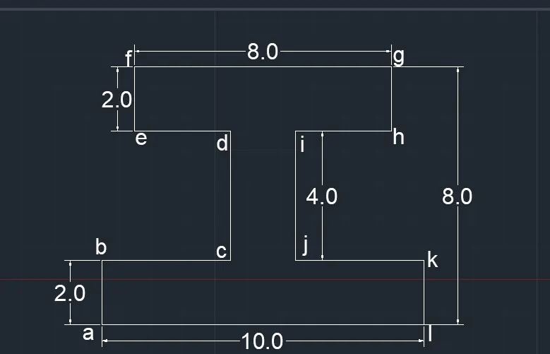
i) ABSOLUTE COORDINATE SYSTEM:
- Give the line command
- Specify first point, a=0,0
- Specify next point, b=0,2
- Specify next point, c=4,2
- Specify next point, d=4,6
- Specify next point, e=1,6
- Specify next point, f=1,8
- Specify next point, g=9,8
- Specify next point, h=9,6
- Specify next point, i=6,6
- Specify next point, j=6,2
- Specify next point, k=10,2
- Specify next point, l=10,0
- then closed. C > Enter
ii) RELATIVE POLAR COORDINATE METHOD :
- a=0,0 starting points
- b=@2<90
- c=@4<0
- d=@4<90
- e=@3<180
- f=@2<90
- g=@8<0
- h=@2<270
- i=@3<180
- j=@4<270
- k=@4<0
- l=@2<270
- then closed, C > Enter
- RESULTS :
EXAMPLE: 7
PROCEDURE
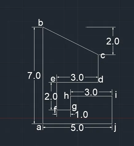
i) ABSOLUTE COORDINATE SYSTEM :
- Line command
- Specify first point, a=1,1
- Specify next point, b=1,8
- Specify next point, c=5,6
- Specify next point, d=5,4
- Specify next point, e=2,4
- Specify next point, f=2,2
- Specify next point, g=3,2
- Specify next point, h=3,3
- Specify next point, i=6,3
- Specify next point, j=6,1
- then closed, C > Enter
- RESULTS :
EXAMPLE: 8
PROCEDURE:
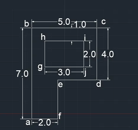
i) ABSOLUTE COORDINATE SYSTEM :
- Give line command
- Specify first point, a=1,1 starting point
- Specify next point, b=1,8
- Specify next point, c=6,8
- Specify next point, d=6,4
- Specify next point, e=3,4
- Specify next point, f=3,1
- closed. C > Enter
- Specify first point, g=2,5
- Specify next point, h=2,7
- Specify next point, i=5,7
- Specify next point, j=5,5
- closed. C > Enter
RELATIVE POLAR COORDINATE SYSTEM:
- Line command
- Entre value, a=1,1
- b=@7<90
- c=@5<0
- d=@4<270
- e=@3<180
- f=@3<270
- closed. C > Enter
- g=2,5 starting point
- h=2<90
- i=3<0
- j=2<270
- closed. C > Enter
- RESULTS:
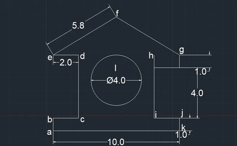
Draw the profile and the trusses using any coordinate system methods. The dimensions are there for references.
EXAMPLE : WOOD
PROCEDURE :
ABSOLUTE COORDINATE METHOD:
- Choose line command
- Specify first point, 0,0 starting point
- Specify next point, 0,1
- Specify next point, 2,1
- Specify next point, 2,6
- Specify next point, 0,6
- Specify next point, 5,9
- Specify next point, 10,6
- Specify next point, 8,5
- Specify next point, 8,1
- Specify next point, 10,1
- Specify next point, 10,0
- closed. C > Enter
- RESULTS :
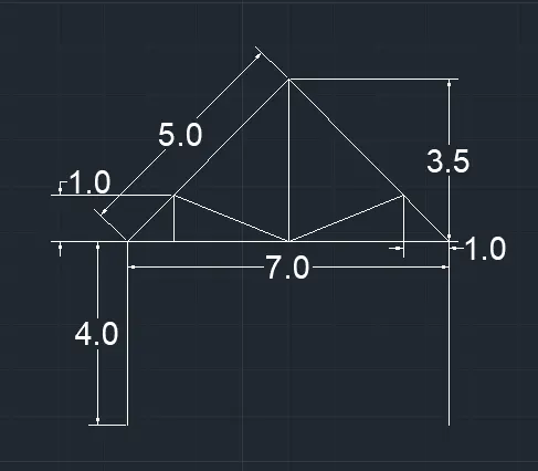
EXAMPLE :QUEEN POST TRUSS
PROCEDURE :
RELATIVE RECTANGULAR COORDINATE SYSTEM :
- Choose line command
- Specify first point, 1,1 starting point
- Specify next point 0,4
- Specify next point 7,0
- Specify next point 0,4
- After that take a centre point of 7 unit line as a first point. Give line command.
- Draw vertical line, 0,3.5
- Then join both left and right corner of 7 unit line to this vertical line.
- Take left corner point as a first point > line command > Specify point 1,1
- Take left corner point as a first point > line command > Specify point -1,1
- Join both @ center of 7,0
RELATIVE POLAR COORDINATE SYSTEM :
- Line command
- 1,1
- @4<90
- @7<0
- @4<270
- enter
- then give the line command
- 1,5 starting point
- @5<45 point f
- enter
- line command
- 8,5
- @5<45
- @3.5<270
- enter
- line command
- 1,5
- @1<0
- @1<90
- joint both point
- and enter
- line commnd
- 8,5
- @1<180
- @1<90
- using line join point
- and press enter
- RESULTS :
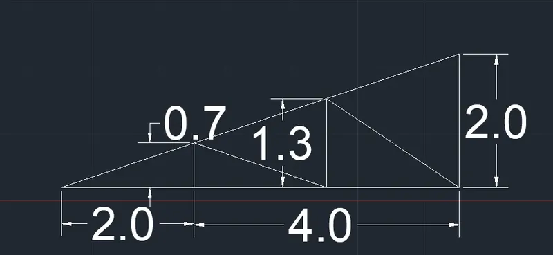
EXAMPLE :MONO PITCH
PROCEDURE:
ABSOLUTE COORDINATE SYSTEM :
- Give line command
- Specify first point 1,1
- Specify next point 3,1
- Specify next point 5,1
- Specify next point 7,3
- then closed, C > Enter
- Give the line command
- Specify first point 3,1
- Specify next point 3,1.66
- Specify next point 5,1
- Specify next point 5,2.33
- Specify next point 7,1
- closed, C > Enter
- RESULTS :
IN THIS WAY THIS ALL EXAMPLES ARE SOLVED BY FOUR TYPES OF COORDINATE SYSTEM NAME GIVEN BELOW :
- ABSOLUTE COORDINATE SYSTEM
- RELATIVE RECTANGULAR COORDINATE SYSTEM
- RELATIVE POLAR COORDINATE METHOD
- DIRECT DISTANCE ENTRY METHOD
- BY USING AUTODESK AUTOCAD 2021 VERSION